1987 SUZUKI GRAND VITARA instrument panel
[x] Cancel search: instrument panelPage 3 of 962
SECTION 0
GENERAL, SPECIAL TOOLS AND
SERVICE MATERIALS
CONTENTS
0-1. IDENTIFICATION NUMBER . . . . . . . . . . . . . . . . . . . . . . . . . . . . . . . . . O-1
0-2. STANDARD SHOP PRACTICES . . . . . . . . . . . . . . . . . . . . . . . . . . . . . . . O-2
0-3.SPECIAL TOOLS.. . . . . . . . . . . . 1.. . . . . . . . . . . . . . . . . . . . . . . . . . . . .
0-4.REQUIRED SERVICE MATERIALS . . . . . . . . . . . . . . . . . . . . . s . . . . . O-9
METRIC INFORMATION . . . . . . . . . . . . . . . . . . . . . , . . . . . . . . . . . . . O-12
O-l. IDENTIFICATION NUMBER
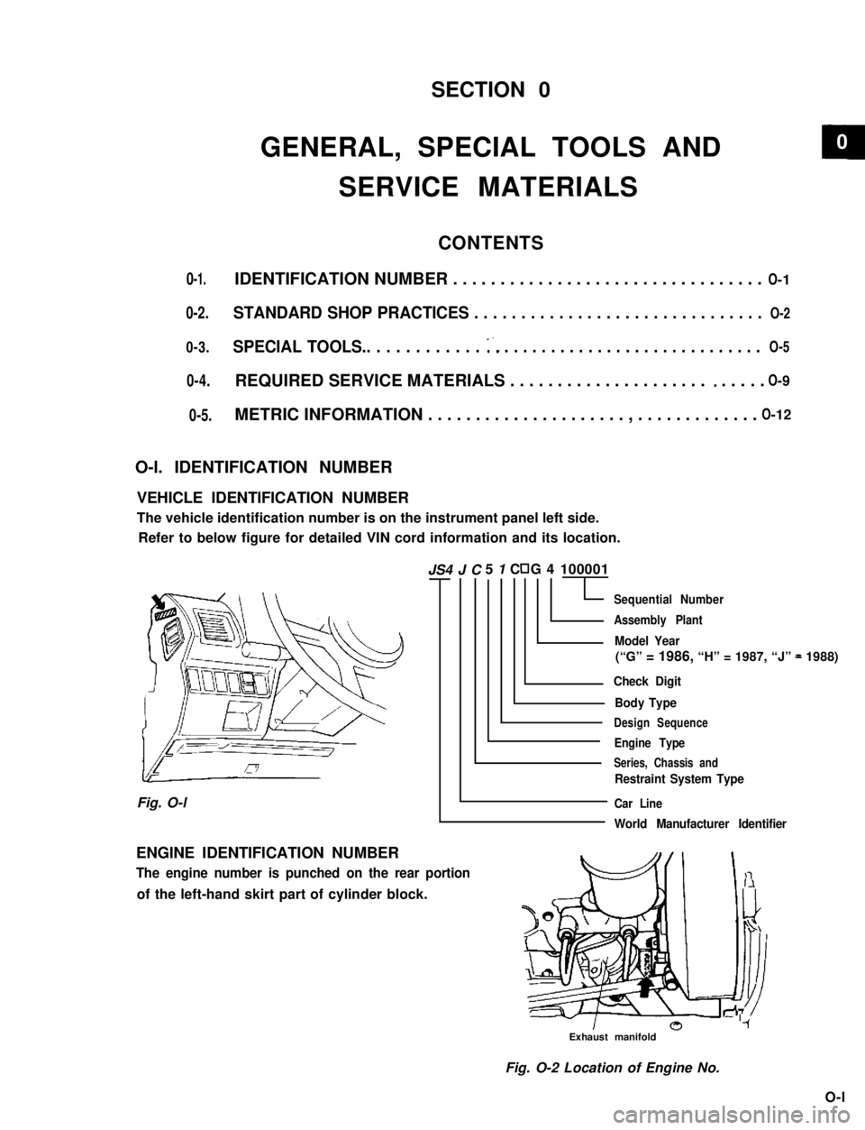
VEHICLE IDENTIFICATION NUMBER
The vehicle identification number is on the instrument panel left side.
Refer to below figure for detailed VIN cord information and its location.
5 1 C G 4 100001
Sequential Number
Assembly Plant
Model Year
(“G” = 1986, “H” = 1987, “J” = 1988)
Check Digit
Body Type
Design Sequence
Engine Type
Series, Chassis and
Restraint System Type
Car Line
World Manufacturer Identifier
Fig. O-l
ENGINE IDENTIFICATION NUMBER
The engine number is punched on the rear portion
of the left-hand skirt part of cylinder block.
Exhaust manifold
Fig. O-2 Location of Engine No.
O-l
JS4 J C
0-5.
O- 5
0
Page 26 of 962
8. PCV VALVE REPLACEMENT
1) Disconnect crankcase ventilation hose from
PCV valve.
2) Remove PCV valve from intake manifold.
3) Wind sealing tape on thread of the new valve
and install it securely.
Tightenlng torque
for PCV valve
15-25 N.m
1.5-2.5 kg-m,
11 .O-18.0 lb-ft
4) Install hose and clamp it securely.
9. OXYGEN SENSOR REPLACEMENT
[Canadian specification vehicle]
When the odometer indicates 50,000 and 100,000
miles, replace oxygen sensor as follows.
CAUTION:
To avoid the danger of being burned, do
not touch the exhaust system when the
system is hot. This work should be perform-
ed when the system is cool.
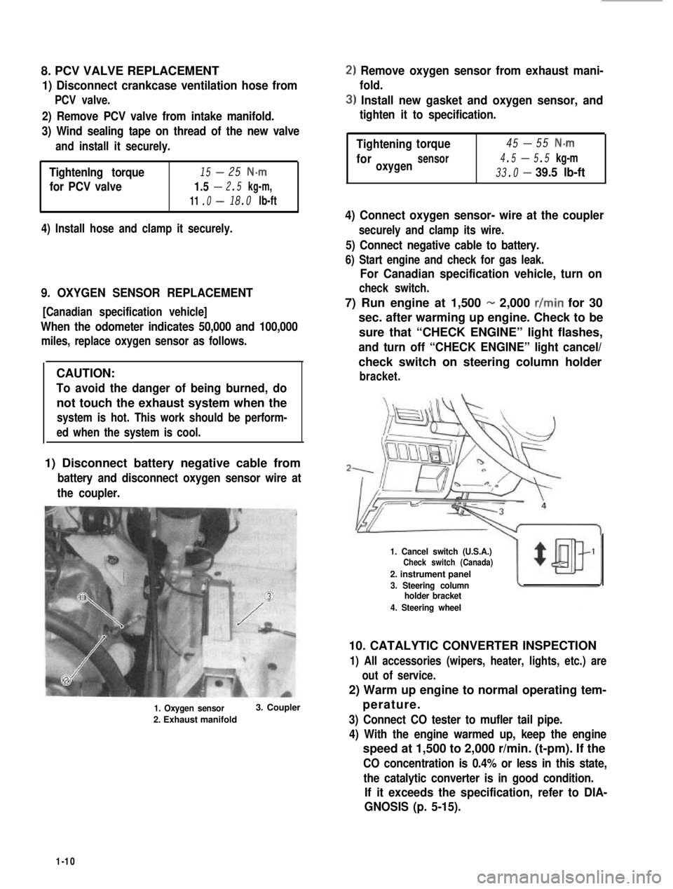
1) Disconnect battery negative cable from
battery and disconnect oxygen sensor wire at
the coupler.
1. Oxygen sensor
2. Exhaust manifold
3. Coupler
2) Remove oxygen sensor from exhaust mani-
fold.
3) Install new gasket and oxygen sensor, and
tighten it to specification.
-Tightening45torque55 N-m
4.5-foroxygensensor5.5 kg-m
33.0-39.5 lb-ft
4) Connect oxygen sensor- wire at the coupler
securely and clamp its wire.
5) Connect negative cable to battery.
6) Start engine and check for gas leak.
For Canadian specification vehicle, turn on
check switch.
7) Run engine at 1,500 - 2,000 r/min for 30
sec. after warming up engine. Check to be
sure that “CHECK ENGINE” light flashes,
and turn off “CHECK ENGINE” light cancel/
check switch on steering column holder
bracket.
1. Cancel switch (U.S.A.)Check switch (Canada)
2. instrument panel
3. Steering columnholder bracket
4. Steering wheel
10. CATALYTIC CONVERTER INSPECTION
1) All accessories (wipers, heater, lights, etc.) are
out of service.
2) Warm up engine to normal operating tem-
perature.
3) Connect CO tester to mufler tail pipe.
4) With the engine warmed up, keep the engine
speed at 1,500 to 2,000 r/min. (t-pm). If the
CO concentration is 0.4% or less in this state,
the catalytic converter is in good condition.
If it exceeds the specification, refer to DIA-
GNOSIS (p. 5-15).
1-10
Page 121 of 962
![SUZUKI GRAND VITARA 1987 Service Repair Manual [Switch vent solenoid]
Provided on top of the float chamber is a switch
vent solenoid which is connected to the ignition
switch through ECM. As the ignition switch is
operated, the solenoid opens and SUZUKI GRAND VITARA 1987 Service Repair Manual [Switch vent solenoid]
Provided on top of the float chamber is a switch
vent solenoid which is connected to the ignition
switch through ECM. As the ignition switch is
operated, the solenoid opens and](/manual-img/20/57437/w960_57437-120.png)
[Switch vent solenoid]
Provided on top of the float chamber is a switch
vent solenoid which is connected to the ignition
switch through ECM. As the ignition switch is
operated, the solenoid opens and closes its valve
so as not to release the fuel vapor in the float
chamber out into the atmosphere.
When the ignition switch is turned to “OFF”
position, the passage connecting the inner vent
passage and the float chamber will close, and the
passage connecting the float chamber and the
canister will open, then the fuel vapor will flow
into the canister.
When the ignition switch is turned to “ON”
position, and engine speed is above 400 r/min,
the passage connecting the float chamber and
the canister will close, and the passage connect-
ing the float chamber and the inner vent passage
will open, then the fuel vapor will flow into the
carburetor bore.
1. Switch vent solenoid
2. Float
3. To canister
4. Inner vent passage
Fig. 4- l-4 Switch vent solenoid
Primary System
[Primary slow system]
The fuel, after passing through the main jet, is
metered by the primary slow jet, then mixed
with the air from the primary slow air No. 2
bleeder. This air/fuel mixture is further blended
with the air from the primary slow air No. 1
bleeder and air supplied through the mixture
control solenoid. Then the air/fuel mixture
passes through the idle down channel and enters
the carburetor bore through the off idle discharge
port and the idle discharge hole.
[Mixture control solenoid valve]
The primary system has the Mixture Control
Solenoid (MCS) Valve. In the MCS, there is a
plunger which makes 16 up and down move-
ments per second by the electrical signals from
the Electronic Control Module (ECM). That is,
when an electrical signal is received by the
solenoid, the plunger will move down and when
no signal is received, the plunger will move up
by the spring force.
When the plunger moves down, the air jet locat-
ed on the upper side of the mixture control
solenoid valve will open as shown in below
figure, allowing the air to flow into the idle
down channel. In this condition, the mixture
will become lean.
On the other hand, when the plunger is pushed
up by the spring, the air jet will close, shutting
off the air flow into the idle down channel. In
this condition, the mixture will become rich.
The up and down movement of the plunger at
the rate of 16 times per second to the signals
from the ECM controls the air/fuel mixture to
the optimum ratio at all times and as a result
helps to improve the emission and engine per-
formances, and fuel economy.
The ECM receives the electrical information
from the oxygen sensor installed to the exhaust
manifold and the engine operating condition
signals from other devices and sends out and
stops the electrical signal to the mixture control
solenoid valve to actuate the plunger up and
down 16 times every second. The ECM is locat-
ed under the glove box of the instrument panel.
4-6
Page 161 of 962
![SUZUKI GRAND VITARA 1987 Service Repair Manual COMPUTER CONTROLLED EMISSION CONTROL SYSTEM
[Feed back system]
A prime purpose of this system is to maintain a controlled air fuel ratio, allowing the catalyst to reduce
oxides of nitrogen, hydrocarbo SUZUKI GRAND VITARA 1987 Service Repair Manual COMPUTER CONTROLLED EMISSION CONTROL SYSTEM
[Feed back system]
A prime purpose of this system is to maintain a controlled air fuel ratio, allowing the catalyst to reduce
oxides of nitrogen, hydrocarbo](/manual-img/20/57437/w960_57437-160.png)
COMPUTER CONTROLLED EMISSION CONTROL SYSTEM
[Feed back system]
A prime purpose of this system is to maintain a controlled air fuel ratio, allowing the catalyst to reduce
oxides of nitrogen, hydrocarbons, carbon monoxide and to improve fuel economy simultaneously.
The electronic control module (ECM) and the oxygen sensor are provided in this system.
The oxygen sensor mounted on the exhaust manifold monitors the exhaust gas air fuel ratio and signals to
the ECM.
The ECM processes the oxygen sensor signal and controls carburetor air fuel ratio by the operation of the
mixture control solenoid in the carburetor.
Thus the signal of the exhaust gas air fuel ratio sensed by the oxygen sensor is fed back to ECM and the
carburetor air fuel ratio is controlled.
[Electronic control module (ECM)]
The ECM controls the fuel cut system, idle-up system, bowl vent system, EGR system and secondary
throttle valve system, as well as the feed back system. The ECM is located under the glove box of the
instrument main panel. Refer to Fig. 5-l -9.
I1
* Engine coolant
temperature
* Engine speed
-Electronic
controlmodule
I I
* Throttle positiont(Micro Switches)
I I I\-
* Fuel cut solenoid valve
-44
* Engine room
- * Vent solenoid valvetempe.rature
* Idle-up actuator (TWSV)* Electric load
* Secondary throttle valve (VSV) , _ ~
r* Mixture control
solenoid valve
* Barometric
pressure
+ ECM supply
voltage
* Gear position
Fig. 5-l-8Computer con trolled emissioncon trot s ys tern
5- 10
Page 162 of 962
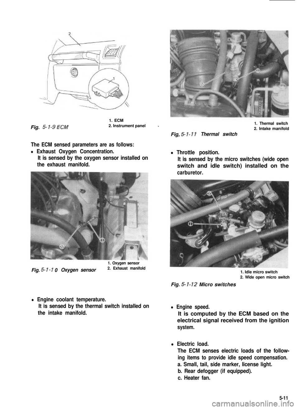
Fig. 5- l-9 ECM
1. ECM
2. Instrument panel.
The ECM sensed parameters are as follows:
l Exhaust Oxygen Concentration.
It is sensed by the oxygen sensor installed on
the exhaust manifold.
1. Oxygen sensor
Fig. 5- I - 7 0Oxygen sensor2. Exhaust manifold
l Engine coolant temperature.
It is sensed by the thermal switch installed on
the intake manifold.
1. Thermal switch
2. Intake manifold
Fig, 5- I- 17Thermal switch
l Throttle position.
It is sensed by the micro switches (wide open
switch and idle switch) installed on the
carburetor.
1. Idle micro switch
2. Wide open micro switch
Fig. 5- 1-12 Micro switches
l Engine speed.
It is computed by the ECM based on the
electrical signal received from the ignition
system.
l Electric load.
The ECM senses electric loads of the follow-
ing items to provide idle speed compensation.
a. Small, tail, side marker, license light.
b. Rear defogger (if equipped).
c. Heater fan.
5-11
Page 174 of 962
Checking feed back system
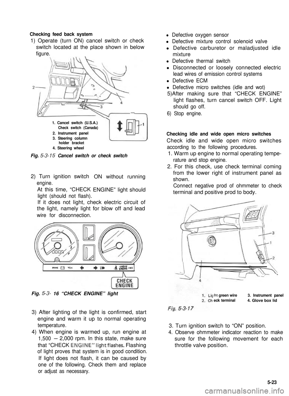
1) Operate (turn ON) cancel switch or check
l Defective oxygen sensor
l Defective mixture control solenoid valve
switch located at the place shown in belowl Defective carburetor or maladjusted idle
figure.mixture
-
1. Cancel switch (U.S.A.)Check switch (Canada)
2. Instrument panel
w
$
1
3. Steering columnholder bracket
4. Steering wheel
Fig. 5-3- 15 Cancel switch or check switch
2) Turn ignition switch
engine.
At this time, “CHECK
ON without running
ENGINE” light should
light (should not flash).
If it does not light, check electric circuit of
the light, namely light for blow off and lead
wire for disconnection.
Fig. 5-3- 16 “CHECK ENGINE” light
3) After lighting of the light is confirmed, start
engine and warm it up to normal operating
temperature.
4) When engine is warmed up, run engine at
1,500- 2,000 rpm. In this state, make sure
that “CHECK ENGINE”lightflashes. Flashing
of light proves that system is in good condition.
If light does not flash, it can be caused by
one of the following. Check them and replace
or adjust as necessary.
l Defective thermal switch
l Disconnected or loosely connected electric
lead wires of emission control systems
l Defective ECM
l Defective micro switches (idle and wot)
5)After making sure that “CHECK ENGINE”
light flashes, turn cancel switch OFF. Light
should go off.
6) Stop engine.
Checking idle and wide open micro switches
Check idle and wide open micro switches
according to the following procedures.
1. Warm up engine to normal operating tempe-
rature and stop engine.
2. For this check, use check terminal coming
from the lower right of instrument panel as
shown.
Connect negative prod of ohmmeter to check
terminal and positive prod to body.
Iht green wire
eck terminal
3. Instrument panel
4. Glove box lid
3. Turn ignition switch to “ON” position.
4. Observe ohmmeter indicator reaction to make
sure for the following movement for each
throttle valve position.
5-23
Page 180 of 962
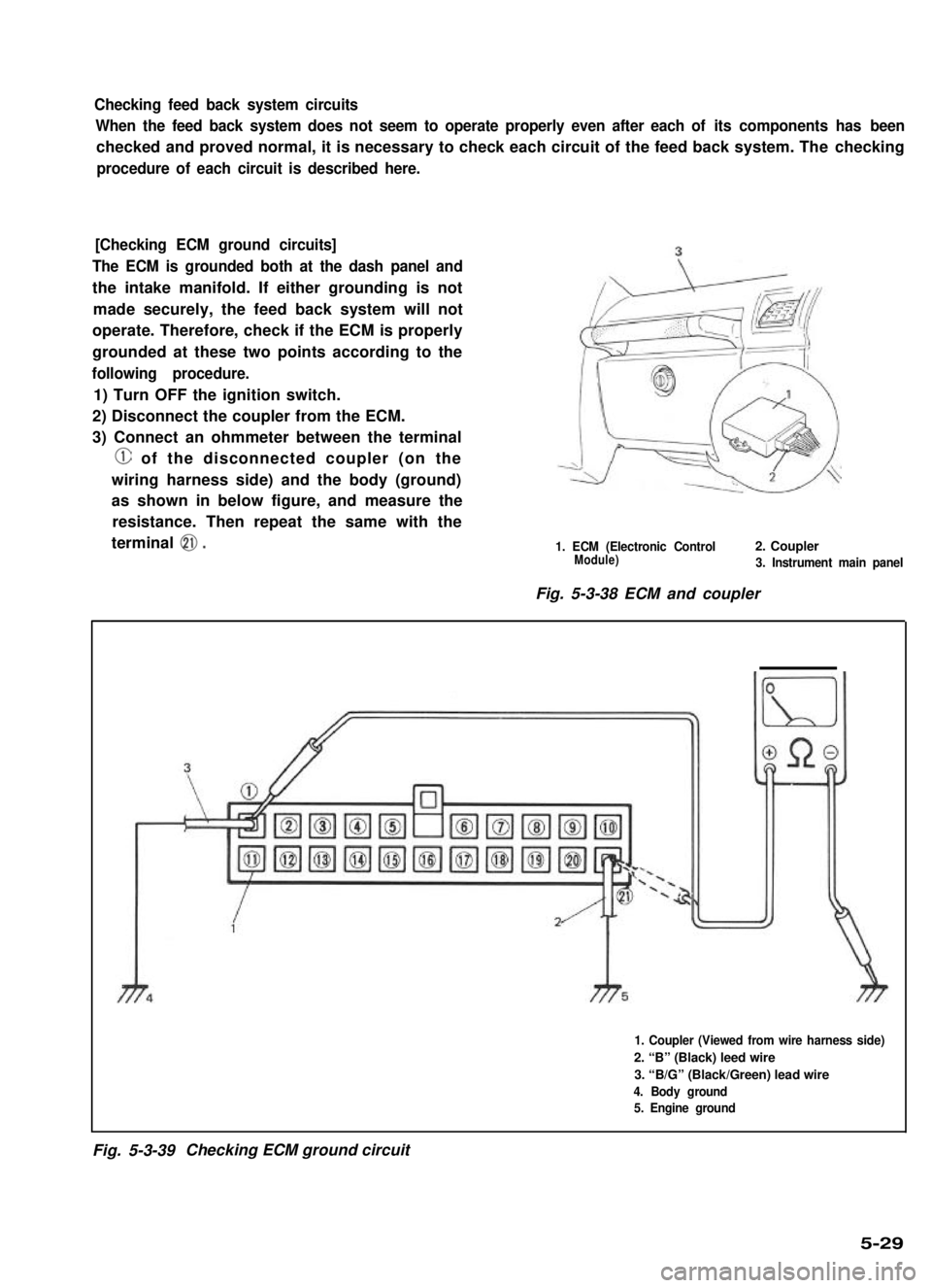
Checking feed back system circuits
When the feed back system does not seem to operate properly even after each of its components has been
checked and proved normal, it is necessary to check each circuit of the feed back system. The checking
procedure of each circuit is described here.
[Checking ECM ground circuits]
The ECM is grounded both at the dash panel and
the intake manifold. If either grounding is not
made securely, the feed back system will not
operate. Therefore, check if the ECM is properly
grounded at these two points according to the
following procedure.
1) Turn OFF the ignition switch.
2) Disconnect the coupler from the ECM.
3) Connect an ohmmeter between the terminal
@ of the disconnected coupler (on the
wiring harness side) and the body (ground)
as shown in below figure, and measure the
resistance. Then repeat the same with the
terminal 0.1. ECM (Electronic Control2. CouplerModule)3. Instrument main panel
Fig. 5-3-38 ECM and coupler
1. Coupler (Viewed from wire harness side)
2. “B” (Black) leed wire
3. “B/G” (Black/Green) lead wire
4. Body ground
5. Engine ground
Fig. 5-3-39Checking ECM ground circuit
5-29
Page 184 of 962
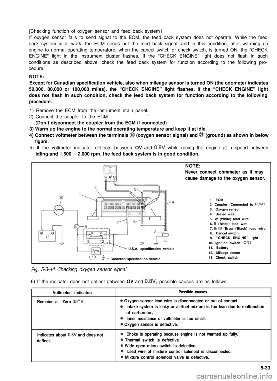
[Checking function of oxygen sensor and feed back system1
If oxygen sensor fails to send signal to the ECM, the feed back system does not operate. While the feed
back system is at work, the ECM sends out the feed back signal, and in this condition, after warming up
engine to normal operating temperature, when the cancel switch or check switch, is turned ON, the “CHECK
ENGINE” light in the instrument cluster flashes. If the “CHECK ENGINE” light does not flash in such
conditions as described above, check the feed back system for function according to the following pro-
cedure.
NOTE:
Except for Canadian specification vehicle, also when mileage sensor is turned ON (the odometer indicates
50,000, 80,000 or 100,000 miles), the “CHECK ENGINE” light flashes. If the “CHECK ENGINE” light
does not flash in such condition, check the feed back system for function according to the following
procedure.
1) Remove the ECM from the instrument main panel.
2) Connect the coupler to the ECM..
(Don’t disconnect the coupler from the ECM if connected)
3) Warm up the engine to the normal operating temperature and keep it at idle.
4) Connect voltmeter between the terminals @I (oxygen sensor signal) and @ (ground) as shown in below
figure.
5) If the voltmeter indicator deflects between OV and 0.8V while racing the engine at a speed between
idling and 1,500 - 2,000 rpm, the feed back system is in good condition.
Fig,
NOTE:
Never connect ohmmeter as it may
cause damage to the oxygen sensor.
U.S.A. specification vehicle
1.ECM2. Coupler (Connected to ECM)
3.Oxygen sensor
4.Sealed wire5. W (White) lead wire
6. I3 (Black) lead wire7. Br/B (Brown/Black) lead wire8.Cancel switch9.“CHECK ENGINE” light
10. Ignition switch (ON)11.Battery
12.Mileage sensor115 'L----JA Canadian specification vehicle
I 5-3-44 Checking oxygen sensor signal
13. Check switch
6) If the indicator does not deflect between OV and 0.8V, possible causes are as follows.
Voltmeter indicator:
Remains at “Zero (0)“V
Possible causes
0 Oxygen sensor lead wire is disconnected or out of contact.
0intake system is leaky or air/fuel mixture is too lean due to malfunction
of carburetor,
0Inner resistance of voltmeter is too small.
0 Oxygen sensor is defective.
Indicates about 0.8V and does not
deflect.
0Choke is operating because engine is not warmed up fully.
0 Thermal switch is defective.
0 Wide open micro switch is defective.
0Lead wire of mixture control solenoid is disconnected.
0 Mixture control solenoid valve is defective.
5-33