Page 185 of 962

7) After it isconfirmed through steps 1) to 5) that oxygen sensor sends signals to ECM properly, check feed
back signal according to the following procedure. If feed back system operates properly, ECM should
send out feed back signal.
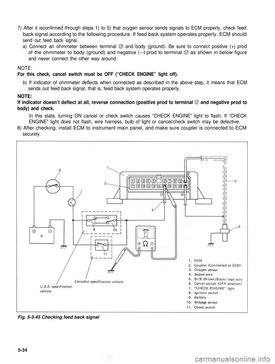
a) Connect an ohmmeter between terminal @I and body (ground). Be sure to connect positive (+) prod
of the ohmmeter to body (ground) and negative (-) prod to terminal @J as shown in below figure
and never connect the other way around.
NOTE:
For this check, cancel switch must be OFF (“CHECK ENGINE” light off).
b) If indicator of ohmmeter deflects when connected as described in the above step, it means that ECM
sends out feed back signal, that is, feed back system operates properly.
NOTE:
If indicator doesn’t deflect at all, reverse connection (positive prod to terminal @ and negative prod to
body) and check.
In this state, turning ON cancel or check switch causes “CHECK ENGINE” light to flash. If “CHECK
ENGINE” light does not flash, wire harness, bulb of light or cancel/check switch may be defective.
8) After checking, install ECM to instrument main panel, and make sure coupler is connected to ECM
securely.
”1,
009
7
kr
1. ECM
2. Coupler (Connected to ECM)3. Oxygen sensor4. Sealed wire
5. Br/B (Brown/Black) lead wire6. Cancel switch (OFF position)
7. “CHECK ENGINE” light
8. Ignition switch9. Battery
/
ICanadian specification vehicle
U.S.A. specificationvehicle
10. Mileage sensor
11. Check switch
Fig. 5-3-45 Checking feed back signal
5-34
Page 208 of 962
![SUZUKI GRAND VITARA 1987 Service Repair Manual 7-4. REMOVAL AND INSTALLATION
Removal
[Heater and blower motor]
1. Disconnect battery negative cable.
2. Drain cooling system.
WARNING:
To help avoid the danger of being burned, do
not remove the drai SUZUKI GRAND VITARA 1987 Service Repair Manual 7-4. REMOVAL AND INSTALLATION
Removal
[Heater and blower motor]
1. Disconnect battery negative cable.
2. Drain cooling system.
WARNING:
To help avoid the danger of being burned, do
not remove the drai](/manual-img/20/57437/w960_57437-207.png)
7-4. REMOVAL AND INSTALLATION
Removal
[Heater and blower motor]
1. Disconnect battery negative cable.
2. Drain cooling system.
WARNING:
To help avoid the danger of being burned, do
not remove the drain plug and the radiator
cap while the engine and radiator are still hot.
Scalding fluid and steam can be blown out
under pressure if the plug and cap are taken
off too soon.
Fig 7-51. Drain plug2. Radiator
3. Disconnect heater inlet and outlet hoses
from heater unit pipes.
4. Remove instrument panel ass’y with speedo-
meter ass’y as follows.
1) Take off horn pad and remove steering
wheel using special tool @.
2) If equipped with radio and cigarette lighter,
disconnect radio and cigarette lighter lead
wires, and pull out radio case with radio
and cigarette lighter after loosening case
stay screw, and remove radio case bracket.
3) Pull out ashtray and loosen ashtray plate
screws.
4) Disconnect front food opening cable from
lock ass’y.
5) Loosen panel box stay screw and hood
opening cable lock nut on back side of
panel box cover.
6) Disconnect lead wires to control lever at
the coupler and heater control cables.
7) Pull out lever knobs and plate, and loosen
lever case screws.
8) Remove defroster and side ventilator hoses.
9) Disconnect lead wires to speedometer and
switches installed instrument panel at the
couplers.
10) Disconnect speedometer cable from speedo-
meter.
11) Release wire harness clamps installed to
instrument panel.
12) Loosen screws securing instrument panel.
13) Remove instrument panel.
NOTE:
l Before removing, recheck to ascertain all
hoses, wire harness, cables and screws are
disconnected from instrument paneL
l When removing heater lever case which is
fitted in steering column holder, be very
careful not to damage it
5. Remove steering column holder after loosen-
ing front door open stopper screws.
Fig. 7-7Fig. 7-6@ Special tool (Steering wheel
remover 09944-360 10)
7-5
Page 368 of 962
18-4. REMOVAL
NOTE:
When removing the column assembly from the
car, special care must be taken in handling it
Use of a steering wheel puller other than the
steering wheel remover recommended in this
manual or a sharp blow on the end of the
steering shaft, leaning on the assembly, or
dropping the assembly is prohibited. Any of
such actions could shear the plastic shear pins
which maintain column length especially.
Steering Hand Wheel
1) Disconnect negative battery cable.
2) Pull horn button to remove.
Fig. 18-3
3) After loosening steering shaft nut, remove
steering wheel by using special tool.
Fig. 18-4 @ Special tool (Steering wheel
remover 09944-36010)
Steering Column
1) After removing steering handwheel according
to the foregoing step, remove steering covers
(lower & upper).
NOTE:
After removing instrument lower panel, loosen
2 screws and 4 nuts securing steering column to
remove upper cover.
Fig. 18-5
18-6
Page 383 of 962
![SUZUKI GRAND VITARA 1987 Service Repair Manual Fig. 18-43 @ Tire tread wear indicator
@ Wear indicating platform
[ Inflation of tires]
l Tire inflation pressures are listed on the
Tire Placard at driver’s side of instrument
panel.
l Tire inflati SUZUKI GRAND VITARA 1987 Service Repair Manual Fig. 18-43 @ Tire tread wear indicator
@ Wear indicating platform
[ Inflation of tires]
l Tire inflation pressures are listed on the
Tire Placard at driver’s side of instrument
panel.
l Tire inflati](/manual-img/20/57437/w960_57437-382.png)
Fig. 18-43 @ Tire tread wear indicator
@ Wear indicating platform
[ Inflation of tires]
l Tire inflation pressures are listed on the
Tire Placard at driver’s side of instrument
panel.
l Tire inflation pressures should be checked
(including spare tire) at least monthly and
when significantly changing the load in the
car.
l Always check tire inflation pressures when
tires are “cold”.
l Always use tire pressure gauge when checking
inflation pressure.
l Be sure to reinstall tire inflation valve caps to
prevent dirt and moisture from getting into
valve core, as they may cause air leakage.
l If air loss occurs while driving, do not drive
on the deflated tire more than is needed to
stop safety. Driving even a short distance on a
deflated tire can damage a tire and wheel
beyond repair.
NOTE:
Before installing wheels, remove any build-up of
corrosion on the wheel mounting surface and
brake drum or disc mounting surface by scraping
and wire brushing. Installing wheels without
good metal-to-metal contact at the mounting
surfaces can cause wheel nuts to loosen, which
can later allow a wheel to come off while the
car is moving.
RADIAL TIRES
.i II
9T
\
I
4-wheels
Fig. 18-44
fT
u
[I
5-wheels
[Wheels]
Wheels must be replaced if they are bent, dented,
have excessive lateral or radial runout, leak air
through welds, have elongated bolt holes, if
lug nuts won’t stay tight, or if they are heavily
rusted. Wheels with greater runout than shown
in below figure may cause objectional vibrations.
Replacement wheels must be equivalent to the
original equipment wheels in load capacity,
diameter,rim width, offset and mounting
configuration. A wheel of improper size or type
may affect wheel and bearing life, brake cooling,
speedometer/odometer calibration, car ground
clearance and tire clearance to the body and
chassis.
[Tire rotation]
“Rotate” tires at the regular intervals in order to
equalize tire wear and thereby make full use of
each tire. Refer to below figure for the scheme
of rotation. Adherence to this scheme prolongs
tire life.
18-20
Page 450 of 962

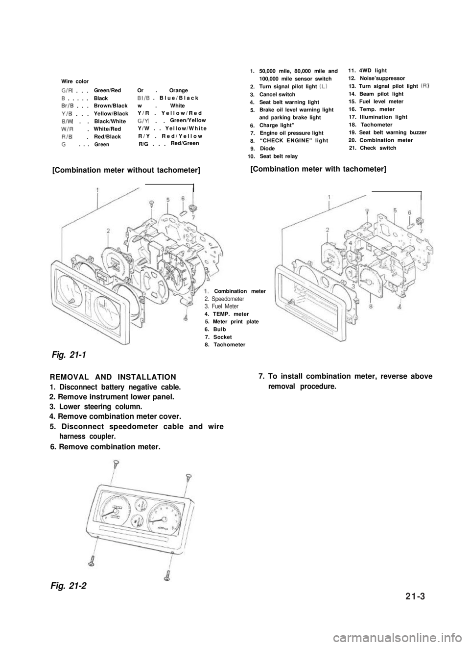
Wire color
G/R . . .Green/RedOr . Orange
0 . . . . .BlackBI/B . Blue/Black
0rlB . . .Brown/Blackw . White
Y/B . . .Yellow/BlackY/R . Yellow/Red
B/W . .Black/WhiteG/Y . .Green/Yellow
W/R .White/RedY/W . . Yellow/White
RIB .Red/BlackR/Y . Red/Yellow
G. . .GreenR/G . . .Red/Green
1.
2.
3.
4.
5.
6.7.
8.
9.
10.
50,000 mile, 80,000 mile and11. 4WD light
100,000 mile sensor switch12. Noise’suppressor
Turn signal pilot light (Lb13. Turn signal pilot light (RI
Cancel switch14. Beam pilot light
Seat belt warning light15. Fuel level meter
Brake oil level warning light16. Temp. meter
and parking brake light17. Illumination light
Charge light”18. Tachometer
Engine oil pressure light19. Seat belt warning buzzer
“CHECK ENGINE" light 20. Combination meter
Diode21. Check switch
Seat belt relay
[Combination meter without tachometer][Combination meter with tachometer]
4. TEMP. meter5. Meter print plate
6. Bulb
7. Socket
Combination meter
Fig. 21-1
8. Tachometer
REMOVAL AND INSTALLATION
1. Disconnect battery negative cable.
2. Remove instrument lower panel.
3. Lower steering column.
4. Remove combination meter cover.
5. Disconnect speedometer cable and wire
harness coupler.
7. To install combination meter, reverse above
removal procedure.
6. Remove combination meter.
Fig. 21-2
2. Speedometer3. Fuel Meter
21-3
Page 468 of 962
Fig. 21-39
Instrument Panel Wiring
1.Wire harness No.2
2. Side marker light3.Head light
4.Earth
5.Washer motor
6. To oil pressure gauge
7. To combination light
16
1.Wire harness No. 1
2.To wire~harness No.2
3.To wire harness No.2
4. To fuse box5.Horn relay
6. To combination switch7.To clutch switch
8.Tostop lampswitch15.Doorwarning buzzer
9. To heater blower motor16. Check relay
10.Toradio17.To wipermotor
Il. To heater fan switch18.To illumination lamp
12. To cigar light19. To optional meter
13.Toradio20.Toclock
14.ToECM21.Tometer
Fig. 21-40
21-21
Page 469 of 962
1.Instrument panel
2.Steering column
3. Steering column holder4.Wiring harness No.1
5. To combination switch
6. To ignition switch
7. To clutch switch
8. Defroster hose9. Brake pedal
10. Clutch pedal
11. Clamp lead wires of ignition switch and combination switch,using care not to allow lead wires to contact the edge of steer-
ing column bracket.
Fig. 21-41
21-16. WIRING DIAGRAM
Wiring diagrams are attached at the end of this manual.
21-22