1987 SUZUKI GRAND VITARA clutch
[x] Cancel search: clutchPage 2 of 962
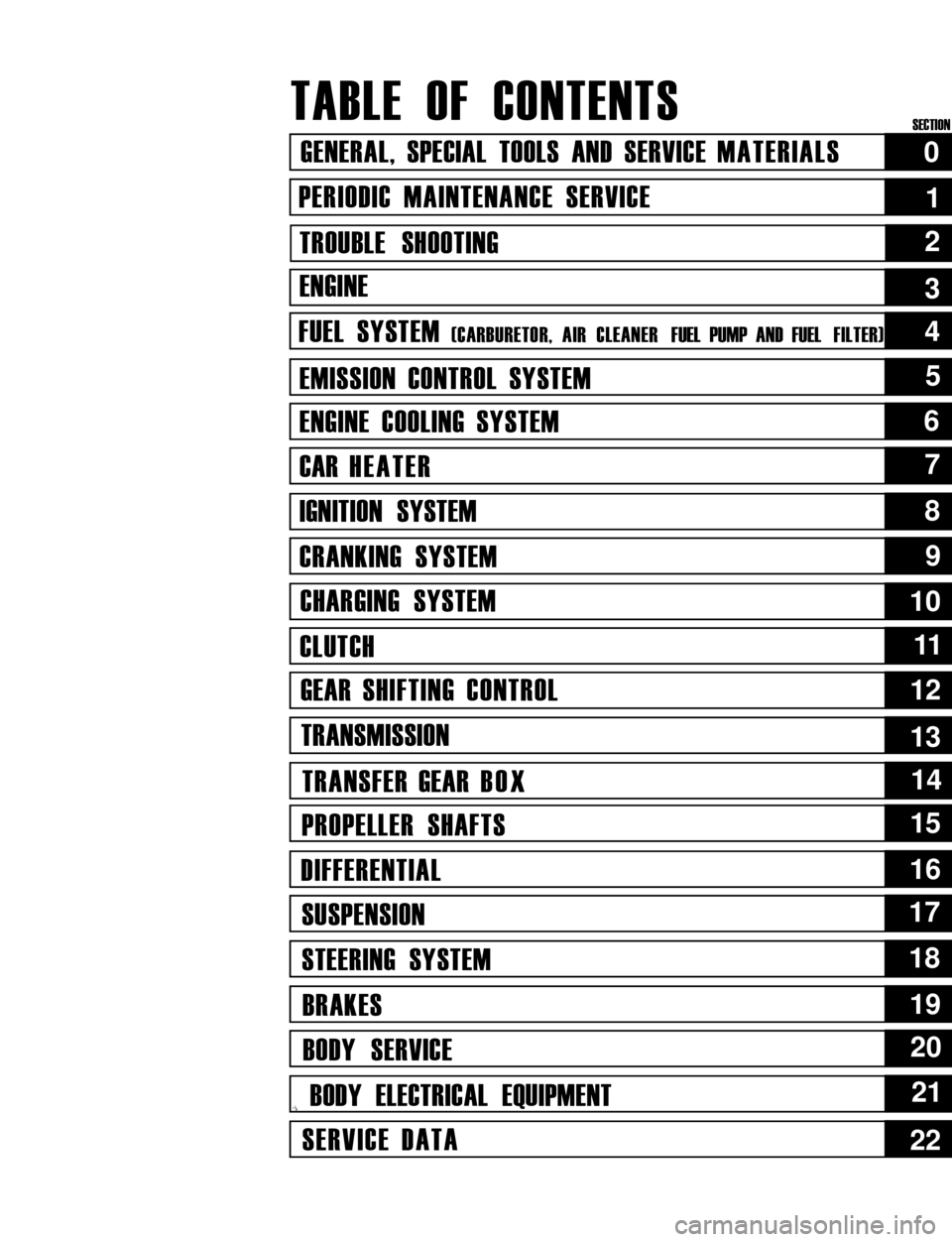
TABLE OF CONTENTS
GENERAL, SPECIAL TOOLS AND SERVICE MATERIALS
PERIODIC MAINTENANCE SERVICE
TROUBLE SHOOTING
ENGINE
FUEL SYSTEM (CARBURETOR, AIR CLEANER FUEL PUMP AND FUEL FILTER)
EMISSION CONTROL SYSTEM
ENGINE COOLING SYSTEM
CAR HEATER
IGNITION SYSTEM
CRANKING SYSTEM
CHARGING SYSTEM
CLUTCH
GEAR SHIFTING CONTROL
TRANSMISSION
TRANSFER GEAR BOX
PROPELLER SHAFTS
DIFFERENTIAL
SUSPENSION
STEERING SYSTEM
BRAKES
BODY SERVICE
,i BODY ELECTRICAL EQUIPMENT
SERVICE DATA
0
1
2
5
6
7
8
9
10
1111
12
13
14
15
16
17
18
19
20
21
22
4
3
SECTION
Page 21 of 962
![SUZUKI GRAND VITARA 1987 Service Repair Manual 1-2. ENGINE AND EMISSION CONTROL
1. WATER PUMP BELT INSPECTION
AND REPLACEMENT
[INSPECTION]
1) Disconnect negative battery lead at battery.
2) Inspect belt for cracks, cuts, deformation,
wear and clea SUZUKI GRAND VITARA 1987 Service Repair Manual 1-2. ENGINE AND EMISSION CONTROL
1. WATER PUMP BELT INSPECTION
AND REPLACEMENT
[INSPECTION]
1) Disconnect negative battery lead at battery.
2) Inspect belt for cracks, cuts, deformation,
wear and clea](/manual-img/20/57437/w960_57437-20.png)
1-2. ENGINE AND EMISSION CONTROL
1. WATER PUMP BELT INSPECTION
AND REPLACEMENT
[INSPECTION]
1) Disconnect negative battery lead at battery.
2) Inspect belt for cracks, cuts, deformation,
wear and cleanliness. If any defect, replace.
Check belt for tension. The belt is in’ proper
tension if it deflects 6 to 9 mm (0.24 - 0.35
in.) under thumb pressure (about 10 kg or
22 lb.)..
Belt tension6 - 9 mm (0.24 - 0.35 in.)
specificationas deflection
pulley
3) If the belt is too tight or too loose, adjust it
to specification by adjusting alternator
position.
4) Tighten alternator adjusting bolt and pivot
bolts.
5) Connect negative battery lead to battery.
[REPLACEMENT]
1) Disconnect negative battery lead at battery.
2) Loosen alternator adjusting bolt and pivot
bolts.
3) Replace water pump belt.
4) Adjust belt tension to specification and
tighten alternator adjusting bolt and pivot
bolts.
5) Connect negative battery lead to battery.
2. CAMSHAFT TIMING BELT INSPECTION
1) Disconnect negative battery lead at battery.
2) Loosen fan drive belt, and remove 4 bolts
securing radiator shroud panel and 4 nuts
securing engine cooling fan & clutch. Then
remove radiator shroud and cooling fan &
clutch at the same time.
3) Remove water pump belt and pump pulley.
4) Remove crankshaft pulley by removing 4
pulley bolts. The crankshaft timing belt
pulley bolt at the center need not be loosen-
ed.2 1
‘31. Key
2. Crankshaft pulley
3. Pulley bolt
1-5
Page 22 of 962
5) Remove timing belt outside cover. Inspect
the belt for damage or wear. When any
damage or wear is found on the belt, replace
it.
If belt replacement is necessary, be sure to
install the belt properly.
6) Remove cylinder head cover and loosen all
valve adjusting screws all the way to permit
free rotation of camshaft.
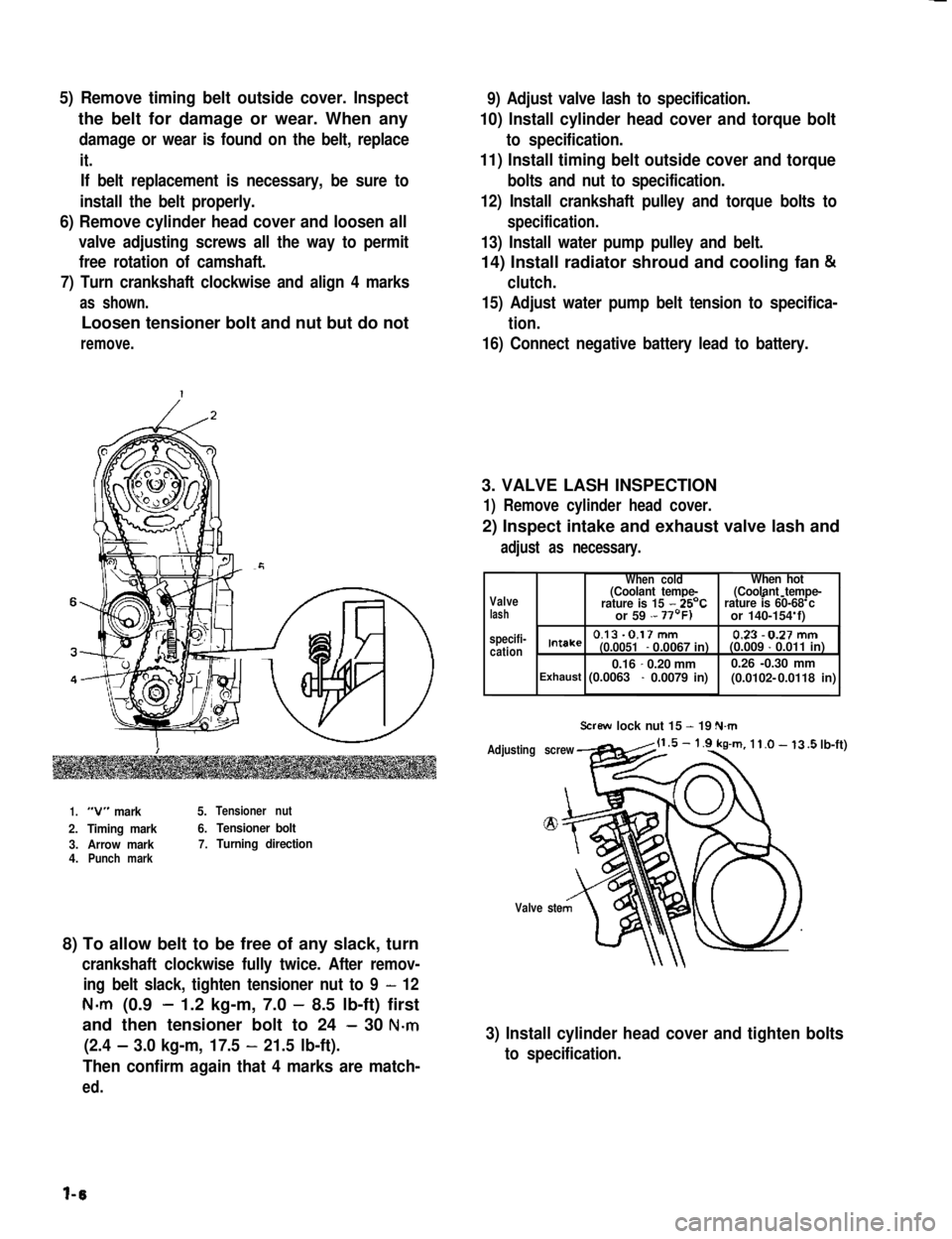
7) Turn crankshaft clockwise and align 4 marks
as shown.
Loosen tensioner bolt and nut but do not
remove.
9) Adjust valve lash to specification.
10) Install cylinder head cover and torque bolt
to specification.
11) Install timing belt outside cover and torque
bolts and nut to specification.
12) Install crankshaft pulley and torque bolts to
specification.
13) Install water pump pulley and belt.
14) Install radiator shroud and cooling fan &
clutch.
15) Adjust water pump belt tension to specifica-
tion.
16) Connect negative battery lead to battery.
3. VALVE LASH INSPECTION
1) Remove cylinder head cover.
2) Inspect intake and exhaust valve lash and
adjust as necessary.
1.“V” mark5.Tensioner nut
2.Timing mark6.Tensioner bolt
3.Arrow mark7.Turning direction4.Punch mark
8) To allow belt to be free of any slack, turn
crankshaft clockwise fully twice. After remov-
ing belt slack, tighten tensioner nut to 9 - 12
N-m (0.9- 1.2 kg-m, 7.0 - 8.5 lb-ft) first
and then tensioner bolt to 24 - 30 N-m
(2.4 - 3.0 kg-m, 17.5 - 21.5 lb-ft).
Then confirm again that 4 marks are match-
ed.
Valvelash specifi-cation
When coldWhen hot(Coolant tempe-(Coolant tempe---rature is 15 - 25’Crature is 60-68 c or 59 - or 140-154 f)
0.13-0.17mm 0.23-0.27mmIntake(0.0051- 0.0067 in)(0.009 - 0.011 in)
0.16-0.20 mm0.26 -0.30 mm(0.0102- Exhaust (0.0063 - 0.0079 in) 0.0118 in)
Screw lock nut 15 - 19 N.m
Adjusting screw
Valve ste
.5 lb-ft)
3) Install cylinder head cover and tighten bolts
to specification.
l-6
Page 33 of 962
1-3. CHASSIS AND BODY
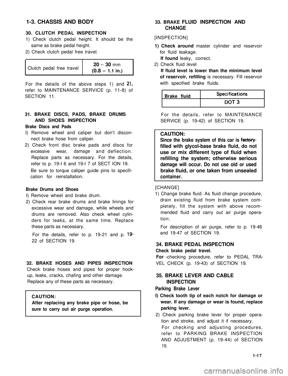
30. CLUTCH PEDAL INSPECTION
1) Check clutch pedal height. It should be the
same as brake pedal height.
2) Check clutch pedal free travel.
Clutch pedal free travel20 - 30 mm
(0.8 - 1.1 in.)
For the details of the above steps 1) and 2),
refer to MAINTENANCE SERVICE (p. 11-8) of
SECTION 11.
31. BRAKE DISCS, PADS, BRAKE DRUMS
AND SHOES INSPECTION
Brake Discs and Pads
I) Remove wheel and caliper but don’t discon-
nect brake hose from caliper.
2) Check front disc brake pads and discs for
excessivewear,damageand deflection.
Replace parts as necessary. For the details,
refer to p. 19-I 6 and 19-I 7 of SECT ION 19.
Be sure to torque caliper guide pins to specifi-
cation for reinstallation.
Brake Drums and Shoes
I) Remove wheel and brake drum.
2) Check rear brake drums and brake linings for
excessive wear and damage, while wheels and
drums are removed. Also check wheel cylin-
ders for leaks, at the same time. Replace
these parts as necessary.
For the details, refer to p. 19-21 and p. 19-
22 of SECTION 19.
32. BRAKE HOSES AND PIPES INSPECTION
Check brake hoses and pipes for proper hook-
up, leaks, cracks, chafing and other damage.
Replace any of these parts as necessary.
CAUTION:
After replacing any brake pipe or hose, be
sure to carry out air purge operation.
33. BRAKE FLUID INSPECTION AND
CHANGE
[INSPECTION]
1) Check around master cylinder and reservoir
for fluid leakage.
If found leaky, correct.
2) Check fluid level
If fluid level is lower than the minimum level
of reservoir, refilling is necessary. Fill reservoir
with specified brake fluids.
Brake fluid Speifi;t3ons
For the details, refer to MAINTENANCE
SERVICE (p. 19-42) of SECTION 19.
CAUTION:
Since the brake system of this car is factory-
filled with glycol-base brake fluid, do not
use or mix different type of fluid when
refilling the system; otherwise serious
damage will occur. Do not use old or used
brake fluid, or one taken from unsealed
container.
[CHANGE]
1) Change brake fluid. As fluid change procedure,
drain existing fluid from brake system com-
pletely, fill the system with above recom-
mended fluid and carry out air purge opera-
tion.
For description of air purge, refer to p. 19-46
and 19-47 of SECTION 19.
34. BRAKE PEDAL INSPECTION
Check brake pedal travel.
For -checking procedure, refer to PEDAL TRA-
VEL CHECK (p. 19-43) of SECTION 19.
35. BRAKE LEVER AND CABLE
INSPECTION
Parking Brake Lever
I) Check tooth tip of each notch for damage or
wear. If any damage or wear is found, replace
parking lever.
2) Check parking brake lever for proper opera-
tion and stroke, and adjust it if necessary.
For checking and adjusting procedures,
refer to PARKING BRAKE INSPECTION
AND ADJUSTMENT (p. 19-44) of SECTION
19.
1-17
Page 38 of 962
FINAL INSPECTION
Carry out road test in safe place.
WARNING:
When carrying out the following road
tests, select a safe place where no man or
no running car is seen so as to prevent any
accident.
1) Engine start
Check engine start for readiness.
2) Clutch
Check the following:
l that clutch is completely released when
depressing clutch pedal,
l that no slipping clutch occurs when releas-
ing pedal and accelerating,
l and that clutch itself is free from any
abnormal condition.
3) Gearshift Lever (Transmission and Transfer)
Check gearshift lever for smooth shifting
to all positions and for good performance of
transmission and transfer in any position.
4) Brake
[Foot brake]
Check the following when depressing brake
pedal while driving;
l that brake works properly,
l that it is free from noise,
l and that braking force applies equally on
all wheels.
[Parking brake]
Check to ensure that parking brake is fully
effective when the car is stopped on the slop
and brake lever is pulled all the way.
5) Steering
Check to ensure that steering wheel is free
from instability, or abnormally heavy feeling
while driving.
1-22
Page 39 of 962

2-1.
2-2.
2-3.
2-4.
2-5.
2-6.
2-7.
2-6.
2-9.
SECTION 2
TROUBLE SHOOTING
CONTENTS
ENGINE...................................................2-2
CARBURETOR...........................................
EXHAUST AND MUFFLER.................................
CLUTCH.................................................2-9
TRANSMISSION..........................................
DIFFERENTIALS.........................................2-11
PROPELLER SHAFTS.....................................2-12
BRAKES.............................................. 2-12
SUSPENSION, STEERING SYSTEM AND TIRES................
STARTING MOTOR.....................................
2-11. ALTERNATOR...........................................
FUEL METER............................................ 2-19
2-14. SPEEDOMETER..........................................2-19
2-15. WATER TEMPERATURE METER.............................2-19
2-9
2-9
2-10
2-14
2-16
2-17
2-18WIPER MOTOR.......................................
2-10.
2-12.
2-13.
2-1
2
Page 42 of 962

ConditionPossible causeCorrection
Not enough powerEmission control
1. Malfunctioning EGR valve
Check and replace as
necessary.
Check and replace as
2. Malfunctioning bowl vent solenoid valve.necessary.
Check and replace as
3. Malfunctioning high altitude switch.necessary
Check nad replace as
4. Malfunctioning throttle position switch
(wide open switch)
necessary
Others
1. Dragging brakes
2. Slipping clutch
.Repair or replace
Adjust or replace
Engine hesitatesAbnormal condition in electrical systems
(Momentary lack of1. Defective spark plug or plug gap out ofReplace or adjust gap
response as the acceler-
ator
adjustment
is depressed. Can2. Cracked rotor or cap in distributor,Replace
occur at all car speeds.resulting in leakage
Usually most severe3. Deteriorated ignition coil, or crackReplace
when first trying toresulting in leakage
make the car move, as4. Leaky high-tension cordsReplace
from a stop sign.)5. Ignition timing out of adjustmentAdjust as prescribed
Abnormal condition in fuel system
1. Improper adjustment of float level
2. Clogged carburetor jets
3. Malfunctioning accelerator pump
Adjust
Clean
Check and replace as
necessary
4. Inadequately discharging fuel pumpReplace
Abnormal condition in engine
1. Loss of compression pressure due to leaky
cylinder head gasket
Replace
2. Compression pressure too low because ofReplace and rebore as
worn pistons, rings, cylinders or burnt valvesnecessary
Emission control
1. Malfunctioning bowl vent solenoid valveCheck and replace as
necessary
2. Malfunctioning throttle position switch
(wide open switch)
3. Malfunctionnig high altitude switch
4. Malfunctioning EGR valve
Check and replace as
necessary
Check and replace as
necessary
Check and replace as
necessary
5. Malfunctioning thermostatically controlled
air cleaner
Check and replace as
necessary
2-4
Page 45 of 962
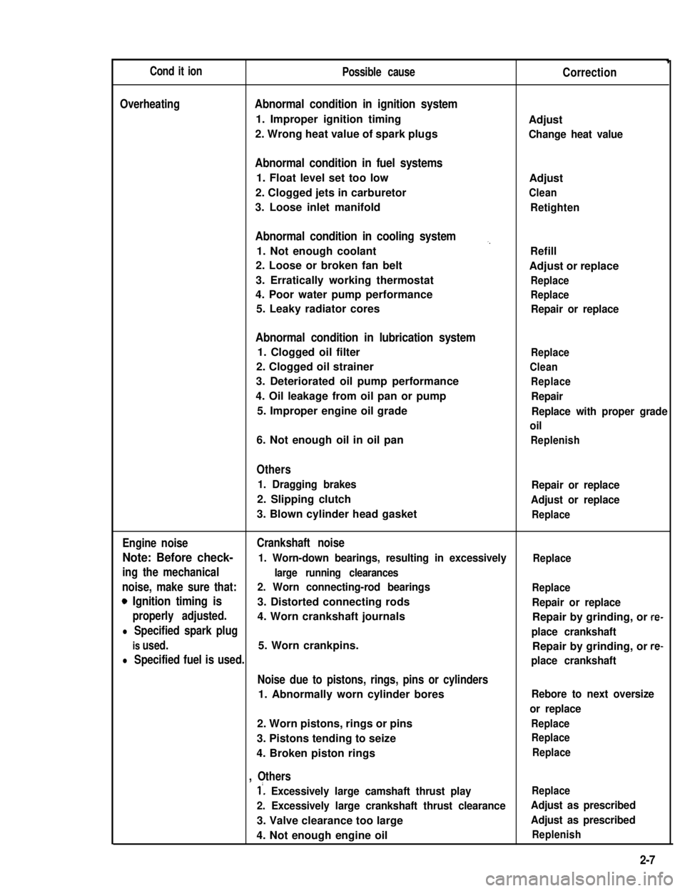
9
Cond it ionPossible causeCorrection
OverheatingAbnormal condition in ignition system
1. Improper ignition timingAdjust
2. Wrong heat value of spark plugsChange heat value
Abnormal condition in fuel systems
1. Float level set too lowAdjust
2. Clogged jets in carburetorClean
3. Loose inlet manifoldRetighten
Abnormal condition in cooling system,,
1. Not enough coolantRefill
2. Loose or broken fan beltAdjust or replace
3. Erratically working thermostatReplace
4. Poor water pump performanceReplace
5. Leaky radiator coresRepair or replace
Abnormal condition in lubrication system
1. Clogged oil filterReplace
2. Clogged oil strainerClean
3. Deteriorated oil pump performanceReplace
4. Oil leakage from oil pan or pumpRepair
5. Improper engine oil gradeReplace with proper grade
oil
6. Not enough oil in oil panReplenish
Others
1. Dragging brakesRepair or replace
2. Slipping clutchAdjust or replace
3. Blown cylinder head gasketReplace
Engine noiseCrankshaft noise
Note: Before check- 1. Worn-down bearings, resulting in excessivelyReplace
ing the mechanicallarge running clearances
noise, make sure that:2. Worn connecting-rod bearingsReplace
0 Ignition timing is3. Distorted connecting rodsRepair or replace
properly adjusted.4. Worn crankshaft journalsRepair by grinding, or re-
l Specified spark plugplace crankshaft
is used.5. Worn crankpins.Repair by grinding, or re-
l Specified fuel is used.place crankshaft
Noise due to pistons, rings, pins or cylinders
1. Abnormally worn cylinder boresRebore to next oversize
or replace
2. Worn pistons, rings or pinsReplace
3. Pistons tending to seizeReplace
4. Broken piston ringsReplace
, Others
1’. Excessively large camshaft thrust playReplace
2. Excessively large crankshaft thrust clearanceAdjust as prescribed
3. Valve clearance too largeAdjust as prescribed
4. Not enough engine oilReplenish
2-7