1987 SUZUKI GRAND VITARA belt
[x] Cancel search: beltPage 21 of 962
![SUZUKI GRAND VITARA 1987 Service Repair Manual 1-2. ENGINE AND EMISSION CONTROL
1. WATER PUMP BELT INSPECTION
AND REPLACEMENT
[INSPECTION]
1) Disconnect negative battery lead at battery.
2) Inspect belt for cracks, cuts, deformation,
wear and clea SUZUKI GRAND VITARA 1987 Service Repair Manual 1-2. ENGINE AND EMISSION CONTROL
1. WATER PUMP BELT INSPECTION
AND REPLACEMENT
[INSPECTION]
1) Disconnect negative battery lead at battery.
2) Inspect belt for cracks, cuts, deformation,
wear and clea](/manual-img/20/57437/w960_57437-20.png)
1-2. ENGINE AND EMISSION CONTROL
1. WATER PUMP BELT INSPECTION
AND REPLACEMENT
[INSPECTION]
1) Disconnect negative battery lead at battery.
2) Inspect belt for cracks, cuts, deformation,
wear and cleanliness. If any defect, replace.
Check belt for tension. The belt is in’ proper
tension if it deflects 6 to 9 mm (0.24 - 0.35
in.) under thumb pressure (about 10 kg or
22 lb.)..
Belt tension6 - 9 mm (0.24 - 0.35 in.)
specificationas deflection
pulley
3) If the belt is too tight or too loose, adjust it
to specification by adjusting alternator
position.
4) Tighten alternator adjusting bolt and pivot
bolts.
5) Connect negative battery lead to battery.
[REPLACEMENT]
1) Disconnect negative battery lead at battery.
2) Loosen alternator adjusting bolt and pivot
bolts.
3) Replace water pump belt.
4) Adjust belt tension to specification and
tighten alternator adjusting bolt and pivot
bolts.
5) Connect negative battery lead to battery.
2. CAMSHAFT TIMING BELT INSPECTION
1) Disconnect negative battery lead at battery.
2) Loosen fan drive belt, and remove 4 bolts
securing radiator shroud panel and 4 nuts
securing engine cooling fan & clutch. Then
remove radiator shroud and cooling fan &
clutch at the same time.
3) Remove water pump belt and pump pulley.
4) Remove crankshaft pulley by removing 4
pulley bolts. The crankshaft timing belt
pulley bolt at the center need not be loosen-
ed.2 1
‘31. Key
2. Crankshaft pulley
3. Pulley bolt
1-5
Page 22 of 962
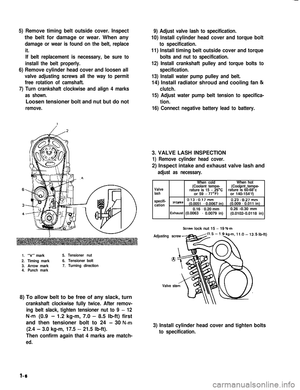
5) Remove timing belt outside cover. Inspect
the belt for damage or wear. When any
damage or wear is found on the belt, replace
it.
If belt replacement is necessary, be sure to
install the belt properly.
6) Remove cylinder head cover and loosen all
valve adjusting screws all the way to permit
free rotation of camshaft.
7) Turn crankshaft clockwise and align 4 marks
as shown.
Loosen tensioner bolt and nut but do not
remove.
9) Adjust valve lash to specification.
10) Install cylinder head cover and torque bolt
to specification.
11) Install timing belt outside cover and torque
bolts and nut to specification.
12) Install crankshaft pulley and torque bolts to
specification.
13) Install water pump pulley and belt.
14) Install radiator shroud and cooling fan &
clutch.
15) Adjust water pump belt tension to specifica-
tion.
16) Connect negative battery lead to battery.
3. VALVE LASH INSPECTION
1) Remove cylinder head cover.
2) Inspect intake and exhaust valve lash and
adjust as necessary.
1.“V” mark5.Tensioner nut
2.Timing mark6.Tensioner bolt
3.Arrow mark7.Turning direction4.Punch mark
8) To allow belt to be free of any slack, turn
crankshaft clockwise fully twice. After remov-
ing belt slack, tighten tensioner nut to 9 - 12
N-m (0.9- 1.2 kg-m, 7.0 - 8.5 lb-ft) first
and then tensioner bolt to 24 - 30 N-m
(2.4 - 3.0 kg-m, 17.5 - 21.5 lb-ft).
Then confirm again that 4 marks are match-
ed.
Valvelash specifi-cation
When coldWhen hot(Coolant tempe-(Coolant tempe---rature is 15 - 25’Crature is 60-68 c or 59 - or 140-154 f)
0.13-0.17mm 0.23-0.27mmIntake(0.0051- 0.0067 in)(0.009 - 0.011 in)
0.16-0.20 mm0.26 -0.30 mm(0.0102- Exhaust (0.0063 - 0.0079 in) 0.0118 in)
Screw lock nut 15 - 19 N.m
Adjusting screw
Valve ste
.5 lb-ft)
3) Install cylinder head cover and tighten bolts
to specification.
l-6
Page 41 of 962
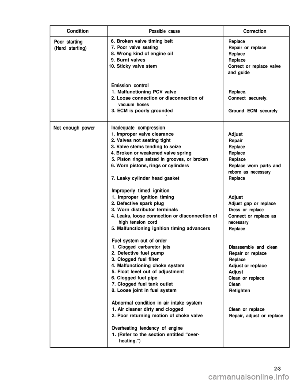
Condition
Poor starting
(Hard starting)
Possible cause
6. Broken valve timing belt
7. Poor valve seating
8. Wrong kind of engine oil
9. Burnt valves
10. Sticky valve stem
Correction
Replace
Repair or replace
Replace
Replace
Correct or replace valve
and guide
Emission control
1. Malfunctioning PCV valve
2. Loose connection or disconnection of
vacuum hoses
Replace.
Connect securely.
3. ECM is poorly grounded.Ground ECM securely
Not enough powerInadequate compression
1. Improper valve clearance
2. Valves not seating tight
3. Valve stems tending to seize
4. Broken or weakened valve spring
5. Piston rings seized in grooves, or broken
6. Worn pistons, rings or cylinders
Adjust
Repair
Replace
Replace
Replace
Replace worn parts and
rebore as necessary
7. Leaky cylinder head gasketReplace
Improperly timed ignition
1. Improper ignition timing
2. Defective spark plug
3. Worn distributor terminals
4. Leaks, loose connection or disconnection of
high tension cord
5. Malfunctioning ignition timing advancers
Adjust
Adjust gap or replace
Dress or replace
Connect or replace as
necessary
Replace
Fuel system out of order
1. Clogged carburetor jets
2. Defective fuel pump
3. Clogged fuel filter
4. Malfunctioning choke system
5. Float level out of adjustment
6. Clogged fuel pipe
7. Clogged fuel tank outlet
8. Loose joint in fuel system
Disassemble and clean
Repair or replace
Replace
Adjust or replace
Adjust
Clean or replace
Clean
Retighten
Abnormal condition in air intake system
1. Air cleaner dirty and clogged
2. Poor returning motion of choke valve
Clean or replace
Repair, adjust or replace
Overheating tendency of engine
1. (Refer to the section entitled “over-
heating.“)
2-3
Page 45 of 962
9
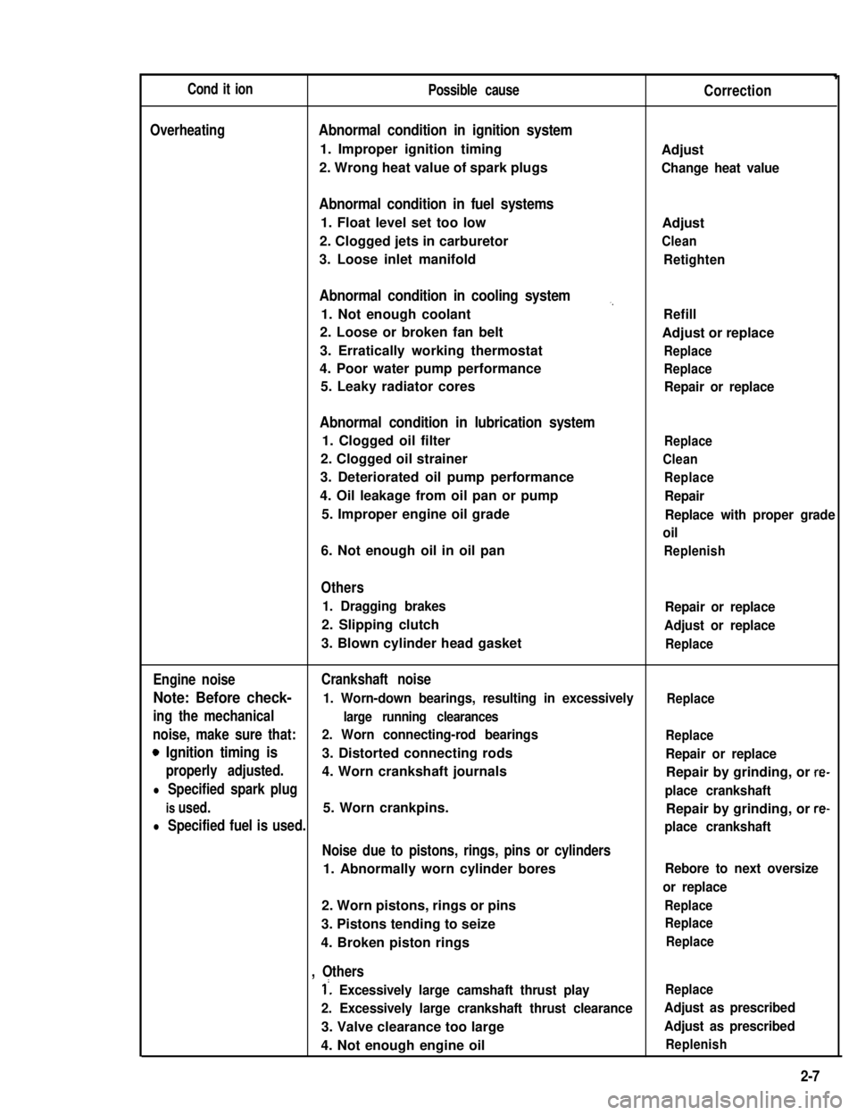
Cond it ionPossible causeCorrection
OverheatingAbnormal condition in ignition system
1. Improper ignition timingAdjust
2. Wrong heat value of spark plugsChange heat value
Abnormal condition in fuel systems
1. Float level set too lowAdjust
2. Clogged jets in carburetorClean
3. Loose inlet manifoldRetighten
Abnormal condition in cooling system,,
1. Not enough coolantRefill
2. Loose or broken fan beltAdjust or replace
3. Erratically working thermostatReplace
4. Poor water pump performanceReplace
5. Leaky radiator coresRepair or replace
Abnormal condition in lubrication system
1. Clogged oil filterReplace
2. Clogged oil strainerClean
3. Deteriorated oil pump performanceReplace
4. Oil leakage from oil pan or pumpRepair
5. Improper engine oil gradeReplace with proper grade
oil
6. Not enough oil in oil panReplenish
Others
1. Dragging brakesRepair or replace
2. Slipping clutchAdjust or replace
3. Blown cylinder head gasketReplace
Engine noiseCrankshaft noise
Note: Before check- 1. Worn-down bearings, resulting in excessivelyReplace
ing the mechanicallarge running clearances
noise, make sure that:2. Worn connecting-rod bearingsReplace
0 Ignition timing is3. Distorted connecting rodsRepair or replace
properly adjusted.4. Worn crankshaft journalsRepair by grinding, or re-
l Specified spark plugplace crankshaft
is used.5. Worn crankpins.Repair by grinding, or re-
l Specified fuel is used.place crankshaft
Noise due to pistons, rings, pins or cylinders
1. Abnormally worn cylinder boresRebore to next oversize
or replace
2. Worn pistons, rings or pinsReplace
3. Pistons tending to seizeReplace
4. Broken piston ringsReplace
, Others
1’. Excessively large camshaft thrust playReplace
2. Excessively large crankshaft thrust clearanceAdjust as prescribed
3. Valve clearance too largeAdjust as prescribed
4. Not enough engine oilReplenish
2-7
Page 55 of 962
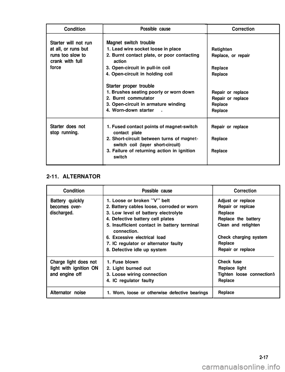
Condition
Starter will not run
at all, or runs but
runs too slow to
crank with full
force
Starter does not
stop running.
2-11. ALTERNATOR
Condition
Battery quickly
becomes over-
discharged.
Charge light does not
light with ignition ON
and engine off
Alternator noise
Possible cause
Magnet switch trouble
1. Lead wire socket loose in place
2. Burnt contact plate, or poor contacting
action
3. Open-circuit in pull-in coil
4. Open-circuit in holding coil
Starter proper trouble
1. Brushes seating poorly or worn down
2. Burnt commutator
3. Open-circuit in armature winding
4. Worn-down starter.
1. Fused contact points of magnet-switch
contact plate
2. Short-circuit between turns of magnet-
switch coil (layer short-circuit)
3. Failure of returning action in ignition
switch
Possible cause
1. Loose or broken “V” belt
2. Battery cables loose, corroded or worn
3. Low level of battery electrolyte
4. Defective battery cell plates
5. Insufficient contact in battery terminal
connection.
6. Excessive electrical load
7. IC regulator or alternator faulty
8. Defective idle up system
1. Fuse blown
2. Light burned out
3. Loose wiring connection
4. IC regulator faulty
1. Worn, loose or otherwise defective bearings
Correction
Retighten
Replace, or repair
Replace
Replace
Repair or replace
Repair or replace
Replace
Replace
Repair or replace
Replace
Replace
Correction
Adjust or replace
Repair or replcae
Replace
Replace the battery
Clean and retighten
Check charging system
Replace
Repair or replace
Check fuse
Replace light
Tighten loose connection!
Replace
i
Replace
2-17
Page 59 of 962
3-1. GENERAL DESCRIPTION
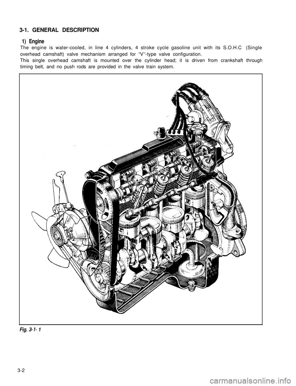
1) Engine
The engine is water-cooled, in line 4 cylinders, 4 stroke cycle gasoline unit with its S.O.H.C (Single
overhead camshaft) valve mechanism arranged for “V’‘-type valve configuration.
This single overhead camshaft is mounted over the cylinder head; it is driven from crankshaft through
timing belt, and no push rods are provided in the valve train system.
Fig. 3- I- 1
3-2
Page 61 of 962
3) Cylinder Head and Valve Train
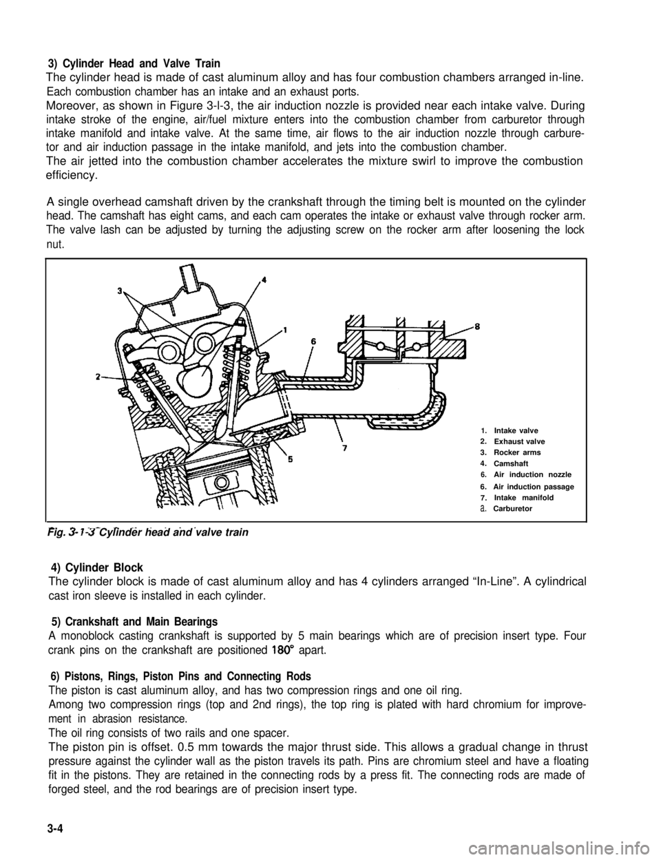
The cylinder head is made of cast aluminum alloy and has four combustion chambers arranged in-line.
Each combustion chamber has an intake and an exhaust ports.
Moreover, as shown in Figure 3-l-3, the air induction nozzle is provided near each intake valve. During
intake stroke of the engine, air/fuel mixture enters into the combustion chamber from carburetor through
intake manifold and intake valve. At the same time, air flows to the air induction nozzle through carbure-
tor and air induction passage in the intake manifold, and jets into the combustion chamber.
The air jetted into the combustion chamber accelerates the mixture swirl to improve the combustion
efficiency.
A single overhead camshaft driven by the crankshaft through the timing belt is mounted on the cylinder
head. The camshaft has eight cams, and each cam operates the intake or exhaust valve through rocker arm.
The valve lash can be adjusted by turning the adjusting screw on the rocker arm after loosening the lock
nut.
2-
1.Intake valve2.Exhaust valve
3.Rocker arms
4.Camshaft
6.Air induction nozzle
6.Air induction passage
7.Intake manifold
a.Carburetor
-. - _- - ._ . . . . .Fig. 3- 7-3 Cylinder head and valve train
4) Cylinder Block
The cylinder block is made of cast aluminum alloy and has 4 cylinders arranged “In-Line”. A cylindrical
cast iron sleeve is installed in each cylinder.
5) Crankshaft and Main Bearings
A monoblock casting crankshaft is supported by 5 main bearings which are of precision insert type. Four
crank pins on the crankshaft are positioned 180” apart.
6) Pistons, Rings, Piston Pins and Connecting Rods
The piston is cast aluminum alloy, and has two compression rings and one oil ring.
Among two compression rings (top and 2nd rings), the top ring is plated with hard chromium for improve-
ment in abrasion resistance.
The oil ring consists of two rails and one spacer.
The piston pin is offset. 0.5 mm towards the major thrust side. This allows a gradual change in thrust
pressure against the cylinder wall as the piston travels its path. Pins are chromium steel and have a floating
fit in the pistons. They are retained in the connecting rods by a press fit. The connecting rods are made of
forged steel, and the rod bearings are of precision insert type.
3-4
Page 62 of 962
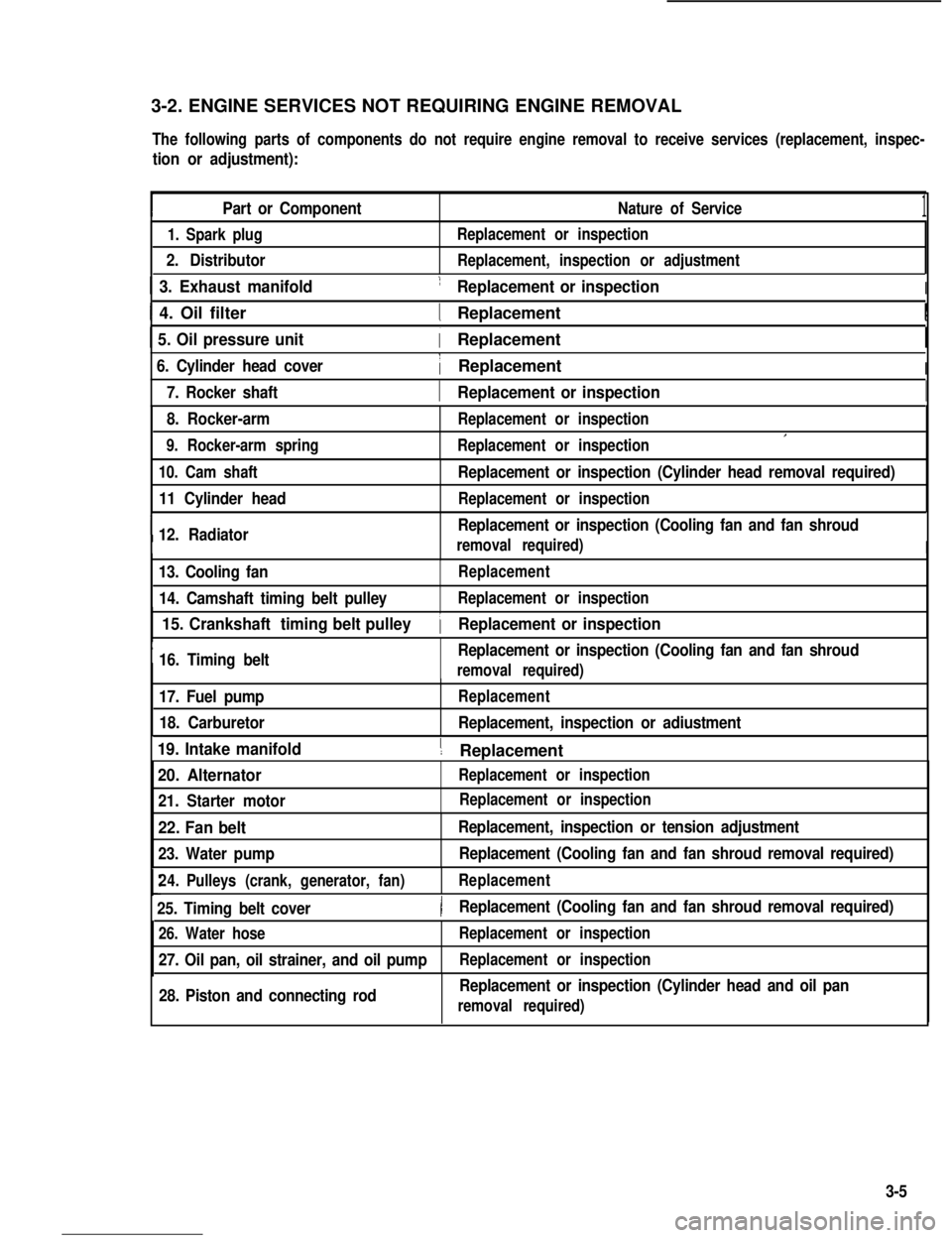
3-2. ENGINE SERVICES NOT REQUIRING ENGINE REMOVAL
The following parts of components do not require engine removal to receive services (replacement, inspec-
tion or adjustment):
Part or ComponentNature of Service1
1. Spark plug
2. Distributor
Replacement or inspection
Replacement, inspection or adjustment
1 3. Exhaust manifold1 Replacement or inspectionI
I 4. Oil filter1 ReplacementI
1 5. Oil pressure unit( Replacement
6. Cylinder head cover1 ReplacementI
I7. Rocker shaft1 Replacement or inspectionI
8. Rocker-arm
9. Rocker-arm spring
Replacement or inspection
Replacement or inspectionI
10. Cam shaft
11 Cylinder head
I12. Radiator
Replacement or inspection (Cylinder head removal required)
Replacement or inspection
Replacement or inspection (Cooling fan and fan shroud
removal required)I
13. Cooling fan
14. Camshaft timing belt pulley
Replacement
Replacement or inspection
I
15. Crankshaft timing belt pulley
16. Timing beltReplacement or inspection (Cooling fan and fan shroud
1 Replacement or inspection
removal required)
17. Fuel pump
18. Carburetor
Replacement
Replacement, inspection or adiustment
19. Intake manifold1 ReplacementI
20. Alternator
21. Starter motor
Replacement or inspection
22. Fan belt
23. Water pump
Replacement, inspection or tension adjustment
Replacement (Cooling fan and fan shroud removal required)
24.Pulleys (crank, generator, fan)Replacement
25. Timing belt cover)Replacement (Cooling fan and fan shroud removal required)
26. Water hose
27. Oil pan, oil strainer, and oil pump
Replacement or inspection
Replacement or inspection
28. Piston and connecting rodReplacement or inspection (Cylinder head and oil pan
removal required)
Replacement or inspection
3-5