Page 111 of 962
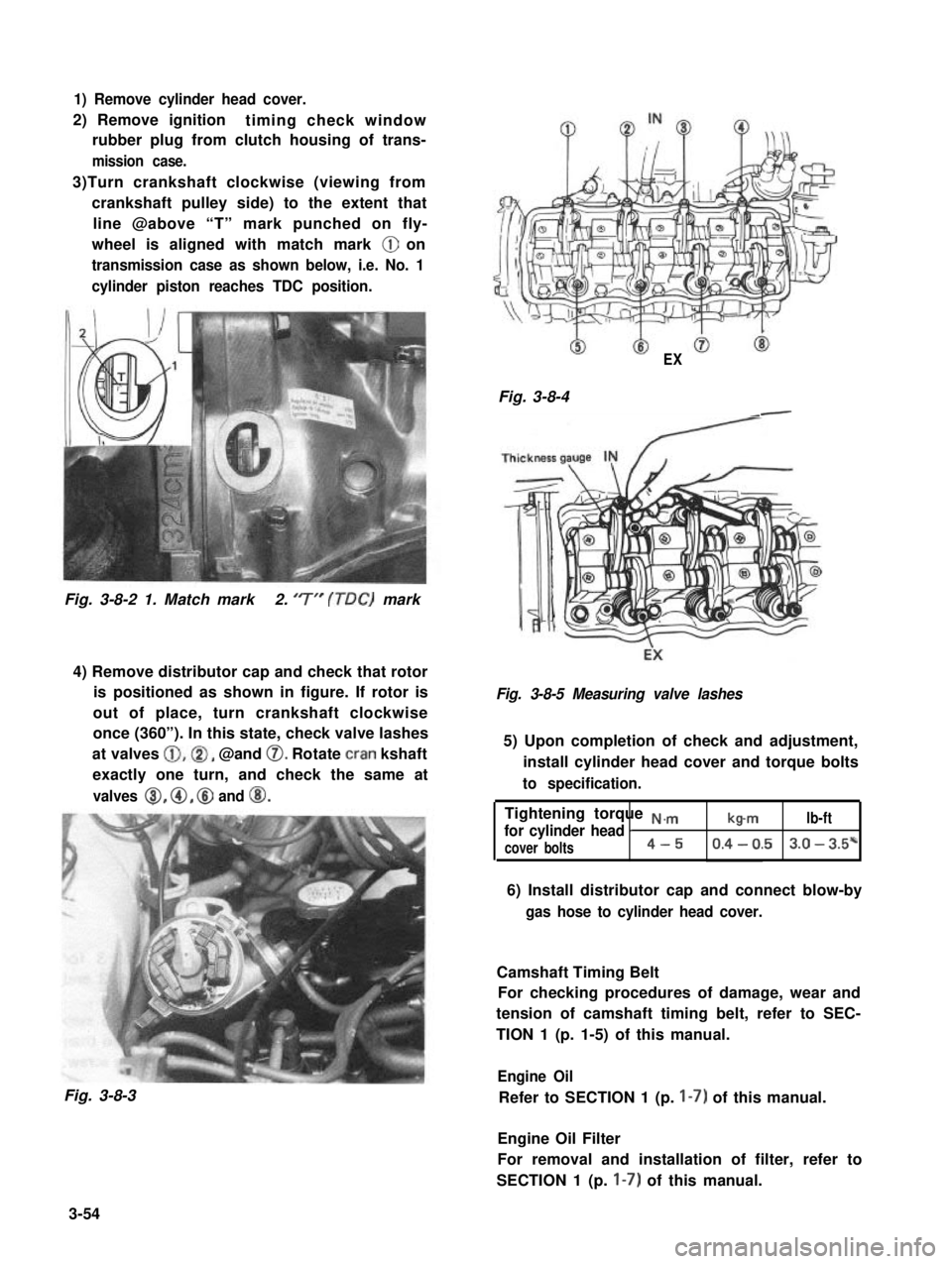
1) Remove cylinder head cover.
2) Remove ignitiontiming check window
rubber plug from clutch housing of trans-
mission case.
3)Turn crankshaft clockwise (viewing from
crankshaft pulley side) to the extent that
line @above “T” mark punched on fly-
wheel is aligned with match mark @ on
transmission case as shown below, i.e. No. 1
cylinder piston reaches TDC position.
Fig. 3-8-2 1. Match mark2. ‘7” (TDC) mark
4) Remove distributor cap and check that rotor
is positioned as shown in figure. If rotor is
out of place, turn crankshaft clockwise
once (360”). In this state, check valve lashes
at valves @,@I, @and 0. Rotate cran kshaft
exactly one turn, and check the same at
valves 8, @, @ and @I.
Fig. 3-8-3
EX
Fig. 3-8-4-
Fig. 3-8-5 Measuring valve lashes
5) Upon completion of check and adjustment,
install cylinder head cover and torque bolts
to specification.
Tightening torque N.,.,.,
for cylinder head Ib-mlb-ft
cover bolts4-50.4 - 0.53.0 - 3.5*
6) Install distributor cap and connect blow-by
gas hose to cylinder head cover.
Camshaft Timing Belt
For checking procedures of damage, wear and
tension of camshaft timing belt, refer to SEC-
TION 1 (p. 1-5) of this manual.
Engine Oil
Refer to SECTION 1 (p. I-7) of this manual.
Engine Oil Filter
For removal and installation of filter, refer to
SECTION 1 (p. I-7) of this manual.
3-54
Page 115 of 962
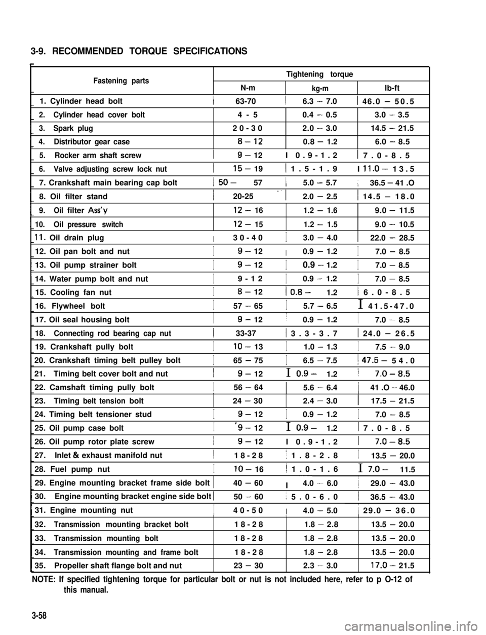
3-9. RECOMMENDED TORQUE SPECIFICATIONS
Fastening partsN-m
Tightening torque
kg-mlb-ft
1. Cylinder head bolt1 63-7016.3 - 7.01 46.0 - 50.5
2.Cylinder head cover bolt4-50.4-0.53.0-3.5
3.Spark plug20-302.0-3.014.5-21.5
4.Distributor gear case8-120.8-1.26.0-8.5
5.Rocker arm shaft screwI9- 12I 0.9-1.21 7.0-8.5
6.Valve adjusting screw lock nut
7. Crankshaft main bearing cap bolt
8. Oil filter stand
I15- 191 1.5-1.9I ll.O- 13.5
1 50- 5715.0 - 5.7136.5 - 41 .O
I20-25 -. 12.0 - 2.51 14.5 - 18.0
9.Oilfilter Ass’y12-161.2-1.69.0-11.5
10.Oilpressure switch12-151.2-1.59.0-10.5
11. Oil drain plugI30-40I3.0 - 4.0122.0 - 28.5
12. Oil pan bolt and nutI9- 12I0.9 - 1.2I7.0 - 8.5
13. Oil pump strainer bolt
14. Water pump bolt and nut
I9- 12I0.9 - 1.2I7.0 - 8.5
I9-12I0.9 - 1.2I7.0 - 8.5
15. Cooling fan nutI8- 121 0.8- 1.21 6.0-8.5
16. Flywheel boltI57 - 65I5.7 - 6.5I 41.5-47.0
17. Oil seal housing boltI9- 12I0.9 - 1.2I7.0 - 8.5
18.Connecting rod bearing cap nut1 33-37( 3.3-3.71 24.0 - 26.5
19. Crankshaft pully boltIlo- 13I1.0 - 1.3I7.5 - 9.0
20. Crankshaft timing belt pulley bolt
21.Timing belt cover bolt and nut
I65 - 75I6.5 - 7.51 47.5- 54.0
I9- 12I 0.9- 1.21 7-O-8.5
22. Camshaft timing pully boltI56 - 6415.6 - 6.4141 .O - 46.0III
23.Timingbelttensionbolt24-302.4-3.0117.5-21.5
24. Timing belt tensioner studI9- 12I0.9 - 1.2I7.0 - 8.5
25. Oil pump case boltI‘9- 12I 0.9- 1.21 7.0-8.5
26. Oil pump rotor plate screwI9- 12I 0.9-1.21 7-O-8.5
27.Inlet & exhaust manifold nutI18-281 1.8-2.8I13.5 - 20.0
28. Fuel pump nutIlo- 161 1.0-1.6I 7.0- 11.5
29. Engine mounting bracket frame side bolt 140 - 60I ~~~4.0 - 6.0129.0 - 43.0
30.Engine mounting bracket engine side bolt I50 - 601 5.0-6.0136.5 - 43.0
31. Engine mounting nutI40-50I4.0 - 5.01 29.0 - 36.0I1I
32.Transmissionmountingbracketbolt18-281.8-2.8113.5-20.0
33.Transmission mounting bolt18-281.8-2.813.5 -20.0
34.Transmission mounting and framebolt18-281.8-2.813.5 -20.0
35.Propeller shaft flange bolt and nut23 - 302.3-3.017.0-21.5
NOTE: If specified tightening torque for particular bolt or nut is not included here, refer to p O-12 of
this manual.
3-58
Page 191 of 962
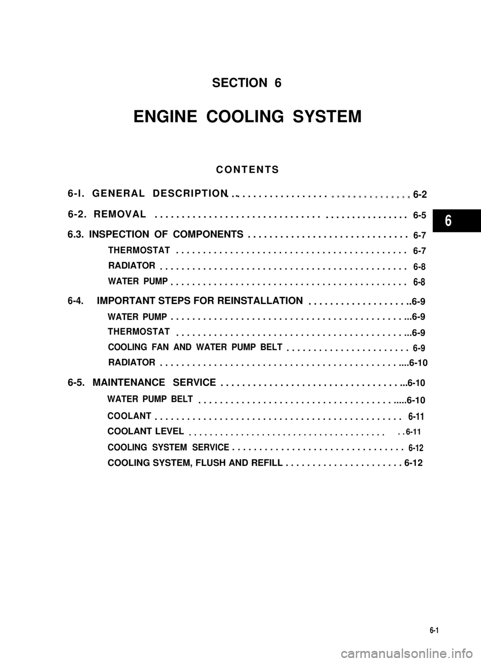
SECTION 6
ENGINE COOLING SYSTEM
CONTENTS
6-l. GENERAL DESCRIPTION .. . . . . . . . . . . . . . . . . . . . ..m..*.........6-2
6-2. REMOVAL...............................................6-5
6.3. INSPECTION OF COMPONENTS..............................6-7
THERMOSTAT...........................................6-7
RADIATOR..............................................6-8
WATER PUMP............................................6-8
6-4.IMPORTANT STEPS FOR REINSTALLATION....................6-9
WATER PUMP..............................................6-9
THERMOSTAT.............................................6-9
COOLING FAN AND WATER PUMP BELT.......................6-9
RADIATOR................................................6-10
6-5. MAINTENANCE SERVICE. . . . . . . . . . . . . . . . . . . . . . . . . . . . . . . . . ...6-10
WATER PUMP BELT.........................................6-10
COOLANT..............................................6-11
COOLANT LEVEL........................................6-11
COOLING SYSTEM SERVICE. . . . . . . . . . . . . . . . . . . . . . . . . . . . . . . .6-12
COOLING SYSTEM, FLUSH AND REFILL . . . . . . . . . . . . . . . . . . . . . . 6-12
6-1
6
Page 192 of 962
6-l. GENERAL DESCRIPTION
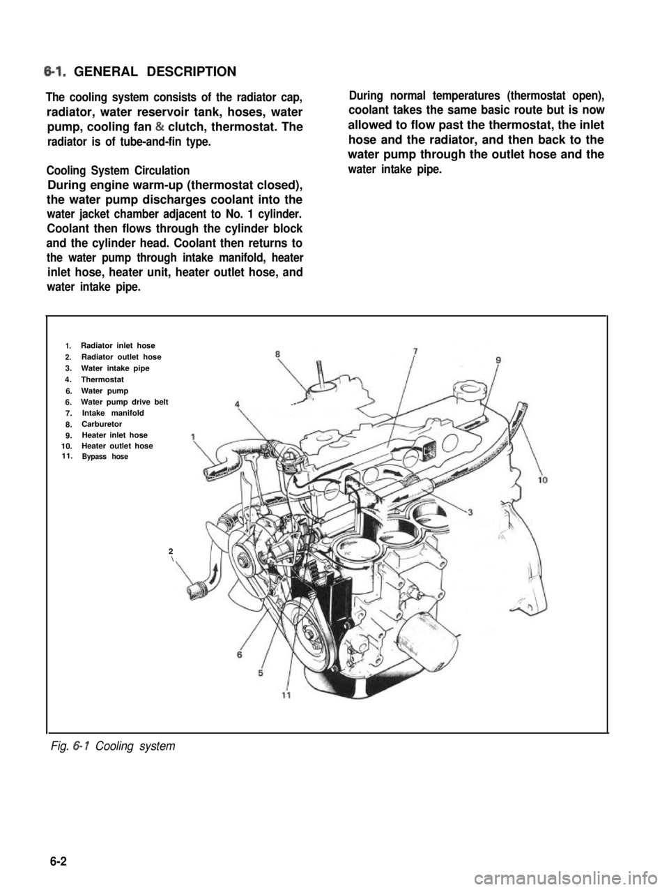
The cooling system consists of the radiator cap,
radiator, water reservoir tank, hoses, water
pump, cooling fan & clutch, thermostat. The
radiator is of tube-and-fin type.
Cooling System Circulation
During engine warm-up (thermostat closed),
the water pump discharges coolant into the
water jacket chamber adjacent to No. 1 cylinder.
Coolant then flows through the cylinder block
and the cylinder head. Coolant then returns to
the water pump through intake manifold, heater
inlet hose, heater unit, heater outlet hose, and
water intake pipe.
During normal temperatures (thermostat open),
coolant takes the same basic route but is now
allowed to flow past the thermostat, the inlet
hose and the radiator, and then back to the
water pump through the outlet hose and the
water intake pipe.
1.Radiator inlet hose
2.Radiator outlet hose
3.Water intake pipe
4.Thermostat
6.Water pump
6.Water pump drive belt
7.Intake manifold
8.Carburetor
9.Heater inlet hose10.Heater outlet hose11.Bypass hose
2\
Fig. 6- 1 Cooling system
6-2
Page 195 of 962
6-2. .REMOVAL
WARNING:
l Check to make sure that cooling water
temperature is cold before removing any
part of cooling system components.
l Also be sure to disconnect 0 cord from
battery 0 terminal before removing any
part.
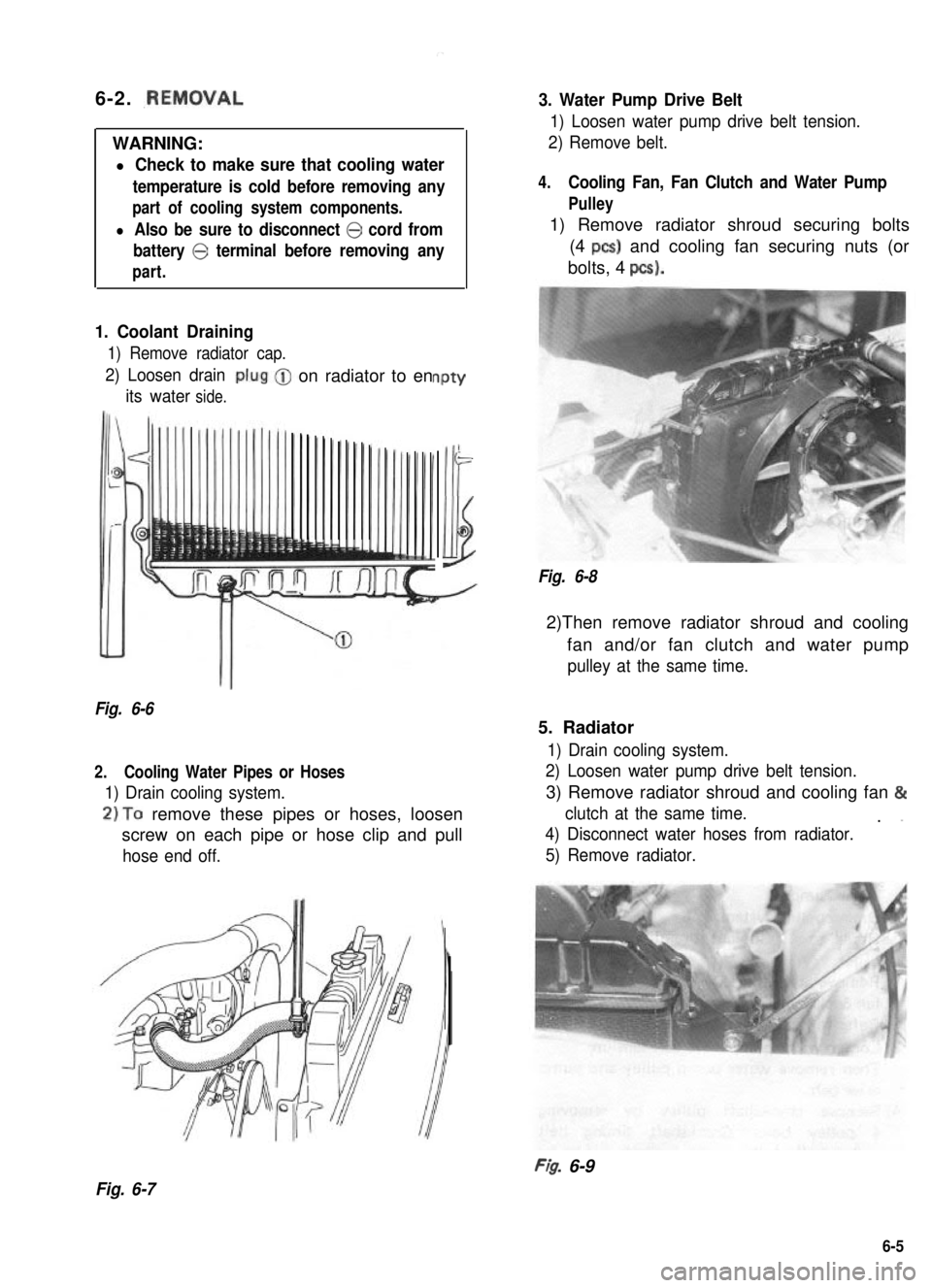
1. Coolant Draining
1) Remove radiator cap.
2) Loosen drain
its waterside.
-on radiator to enPtY
-
Illi
Fig. 6-6
2.Cooling Water Pipes or Hoses
1) Drain cooling system.
2)To remove these pipes or hoses, loosen
screw on each pipe or hose clip and pull
hose end off.
3. Water Pump Drive Belt
1) Loosen water pump drive belt tension.
2) Remove belt.
4.Cooling Fan, Fan Clutch and Water Pump
Pulley
1) Remove radiator shroud securing bolts
(4 PCS) and cooling fan securing nuts (or
bolts, 4 pcs).
Fig. 6-8
2)Then remove radiator shroud and cooling
fan and/or fan clutch and water pump
pulley at the same time.
5. Radiator
1) Drain cooling system.
2) Loosen water pump drive belt tension.
3) Remove radiator shroud and cooling fan &
clutch at the same time.. ”
4) Disconnect water hoses from radiator.
5) Remove radiator.
FI& 6-9
Fig. 6-7
6-5
Page 196 of 962
6. Thermostat
1) Drain cooling system.
2) Disconnect thermostat cap from intake
manifold.
Fig. 6-10
3) Remove thermostat.
1. Crankshaft pulley2. Crankshaft pulley bolt
3.Crank timing belt pulley bolt
Fig. 6- 12
5) Remove timing belt outside cover.
I
Fig. 6- 11Fig. 6- 13
7. Water Pump
1) Drain cooling system.
Refer to 1. Coolant draining on previous
page.
2) Remove the radiator shroud and cooling
fan & clutch at the same time.
Refer to item 4 on previous page.
3) Loosen water pump drive belt tension.
Then remove water pump pulley and pump
drive belt.
4) Remove crankshaft pulley by removing
4 pulley bolts. Crankshaft timing belt
pulley bolt at the center is needs not to be
loosened.
6-6
Page 197 of 962
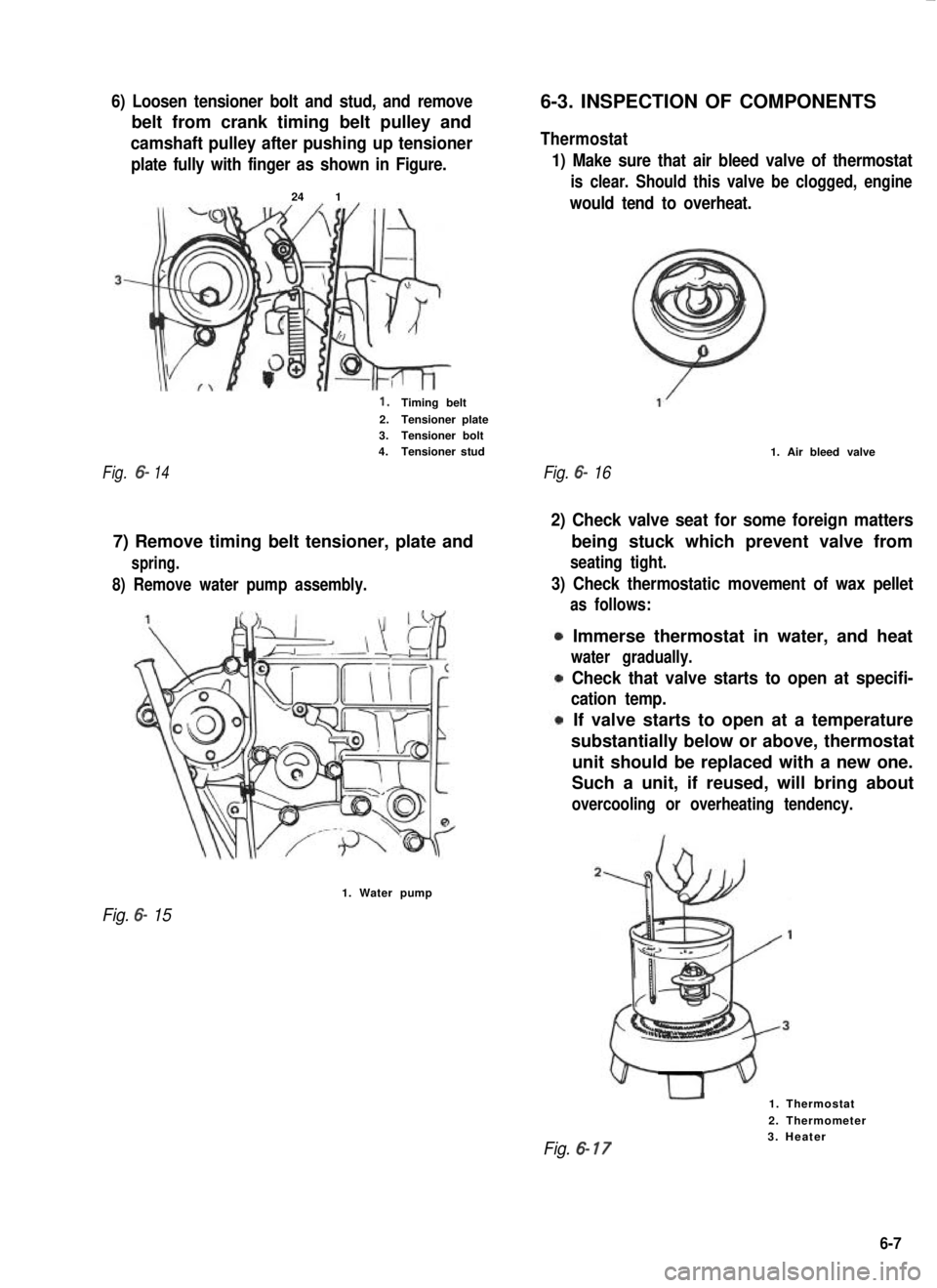
6) Loosen tensioner bolt and stud, and remove
belt from crank timing belt pulley and
camshaft pulley after pushing up tensioner
plate fully with finger as shown in Figure.
24 1
1.Timing belt
2.Tensioner plate3.Tensioner bolt4.Tensioner stud
Fig.6-14
8) Remove water pump assembly.
7) Remove timing belt tensioner, plate and
spring.
1. Water pump
Fig. 6- 15
6-3. INSPECTION OF COMPONENTS
Thermostat
1) Make sure that air bleed valve of thermostat
is clear. Should this valve be clogged, engine
would tend to overheat.
Fig. 6- 16
1. Air bleed valve
2) Check valve seat for some foreign matters
3) Check thermostatic movement of wax pellet
being stuck which prevent valve from
seating tight.
as follows:
Immerse thermostat in water, and heat
water gradually.
Check that valve starts to open at specifi-
cation temp.
If valve starts to open at a temperature
substantially below or above, thermostat
unit should be replaced with a new one.
Such a unit, if reused, will bring about
overcooling or overheating tendency.
1. Thermostat
2. Thermometer
Fig. 6- 173. Heater
6-7
Page 199 of 962
6-4. IMPORTANT STEPS FOR
REINSTALLATION
Water Pump
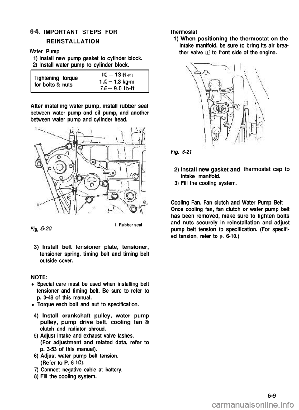
1) Install new pump gasket to cylinder block.
2) Install water pump to cylinder block.
Tightening torque
for bolts & nuts
lo- 13 N-m
1 .O - 1.3 kg-m
7.5 - 9.0 lb-ft
After installing water pump, install rubber seal
between water pump and oil pump, and another
between water pump and cylinder head.
Fig, 6-201. Rubber seal
3) Install belt tensioner plate, tensioner,
tensioner spring, timing belt and timing belt
outside cover.
NOTE:
l Special care must be used when installing belt
tensioner and timing belt. Be sure to refer to
p. 3-48 of this manual.
l Torque each bolt and nut to specification.
4) Install crankshaft pulley, water pump
pulley, pump drive belt, cooling fan &
clutch and radiator shroud.
5) Adjust intake and exhaust valve lashes.
(For adjustment and related data, refer to
p. 3-53 of this manual).
6) Adjust water pump belt tension.
(Refer to P. 6-10).
7) Connect negative cable at battery.
8) Fill the cooling system.
Thermostat
1) When positioning the thermostat on the
intake manifold, be sure to bring its air brea-
ther valve (iJ to front side of the engine.
Fig. 6-21
2) Install new gasket and
intake manifold.
3) Fill the cooling system.
thermostat cap to
Cooling Fan, Fan clutch and Water Pump Belt
Once cooling fan, fan clutch or water pump belt
has been removed, make sure to tighten bolts
and nuts securely in reinstallation and adjust
pump belt tension to specification. (For specifi-
ed tension, refer to p. 6-10.)
6-9