1987 SUZUKI GRAND VITARA belt
[x] Cancel search: beltPage 200 of 962
Radiator6-5. MAINTENANCE SERVICE
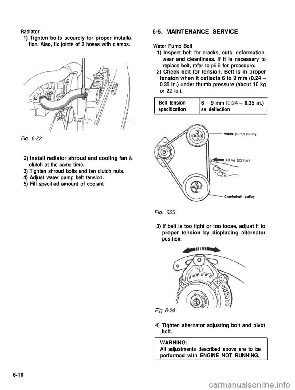
1) Tighten bolts securely for proper installa-
tion. Also, fix joints of 2 hoses with clamps.
Fig. 6-22
2) Install radiator shroud and cooling fan &
clutch at the same time.
3) Tighten shroud bolts and fan clutch nuts.
4) Adjust water pump belt tension.
5) Fill specified amount of coolant.
Water Pump Belt
1) Inspect belt for cracks, cuts, deformation,
wear and cleanliness. If it is necessary to
replace belt, refer to ~6-5 for procedure.
2) Check belt for tension. Belt is in proper
tension when it deflects 6 to 9 mm (0.24 -
0.35 in.) under thumb pressure (about 10 kg
or 22 lb.).
Belt tension
specification
6 - 9 mm (0:24 - 0.35 in.)
as deflectionI
Water pump pulley
Crankshaft pulley
Fig. 623
3) If belt is too tight or too loose, adjust it to
proper tension by displacing alternator
position.
Fig. 6-
4) Tighten alternator adjusting bolt and pivot
bolt.
WARNING:
All adjustments described above are to be
performed with ENGINE NOT RUNNING.
6-10
Page 237 of 962
A. Faulty Indicator Lamp Operation
Problem
Charge light does not light
with ignition ON and engine
off
Charge light does not go out
with engine running
(battery requires frequent
re-
charging) Possible cause
Correcti on
Fuse blown
Check fuse
Light burned outReplace light
Wiring connection loose Tighten loose connections
IC regulator faultyReplace IC regulator
Drive belt loose or worn Adjust or replace drive belt
Battery cables loose, corroded or worn Repair or replace cables
IC regulator or alternator faultyCheck charging system
Wiring faulty.Repair wiring
B. Undercharged Battery a. Voltmeter
This condition, as shown by slow cranking or indicator clear with red dot, can be caused by
one or more of the following conditions even
though the indicator lamp may be operating
normally. The following procedures also apply
to cars with a voltmeter.
1) Insure that the undercharged condition has
not been caused by accessories left on for
extended period.
2) Check drive belt for proper tension.
3) If a battery defect is suspected, refer to
latter part of this section, p. 10-l 0 - p, 1 O-
11.
4) Inspect wiring for defects. Check all connec- tions for tightness and cleanliness, including
slip connectors at alternator and bulkhead,
and battery cable connections at battery,
starter and ignition ground cable.
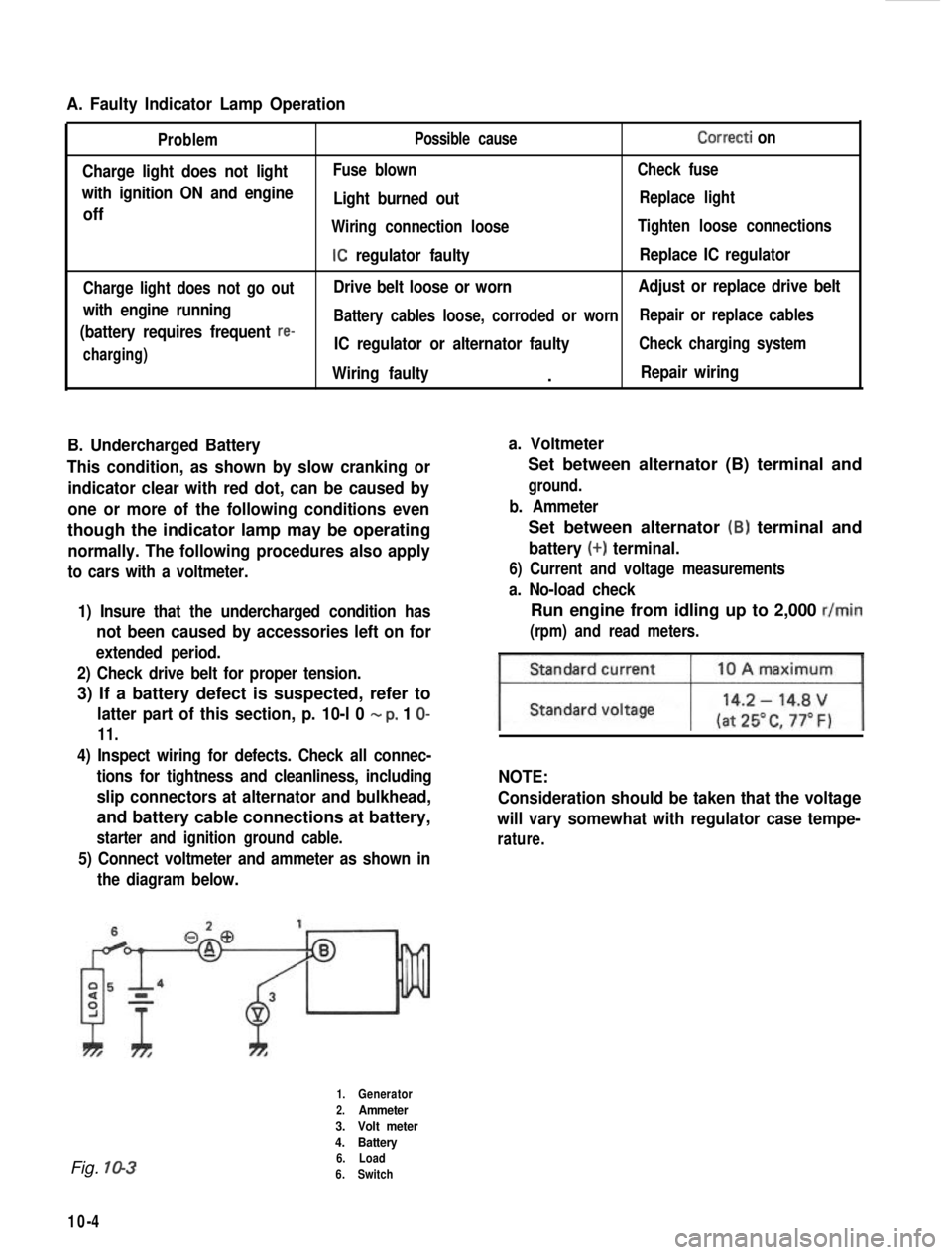
5) Connect voltmeter and ammeter as shown inthe diagram below.
Set between alternator (B) terminal and
ground.
b. Ammeter
Set between alternator (B) terminal and
battery (+) terminal.
6) Current and voltage measurements
a. No-load check
Run engine from idling up to 2,000 r/min
(rpm) and read meters.
NOTE:
Consideration should be taken that the voltage
will vary somewhat with regulator case tempe-
rature.
Fig. 10-3
10-4
1.Generator
2.Ammeter
3. Volt meter
4. Battery
6. Load
6. Switch
Page 239 of 962
ALTERNATOR SERVICE
REMOVAL
1) Remove battery (-) terminal.
2) Disconnect alternator lead wires (coupler & white lead wire).
3) Unclamp brake pipe from pipe clamp on radiator under cover and remove radiator under cover.
4) Remove alternator mounting bolts and alternator drive belt adjusting bolt.
5) Take down alternator.
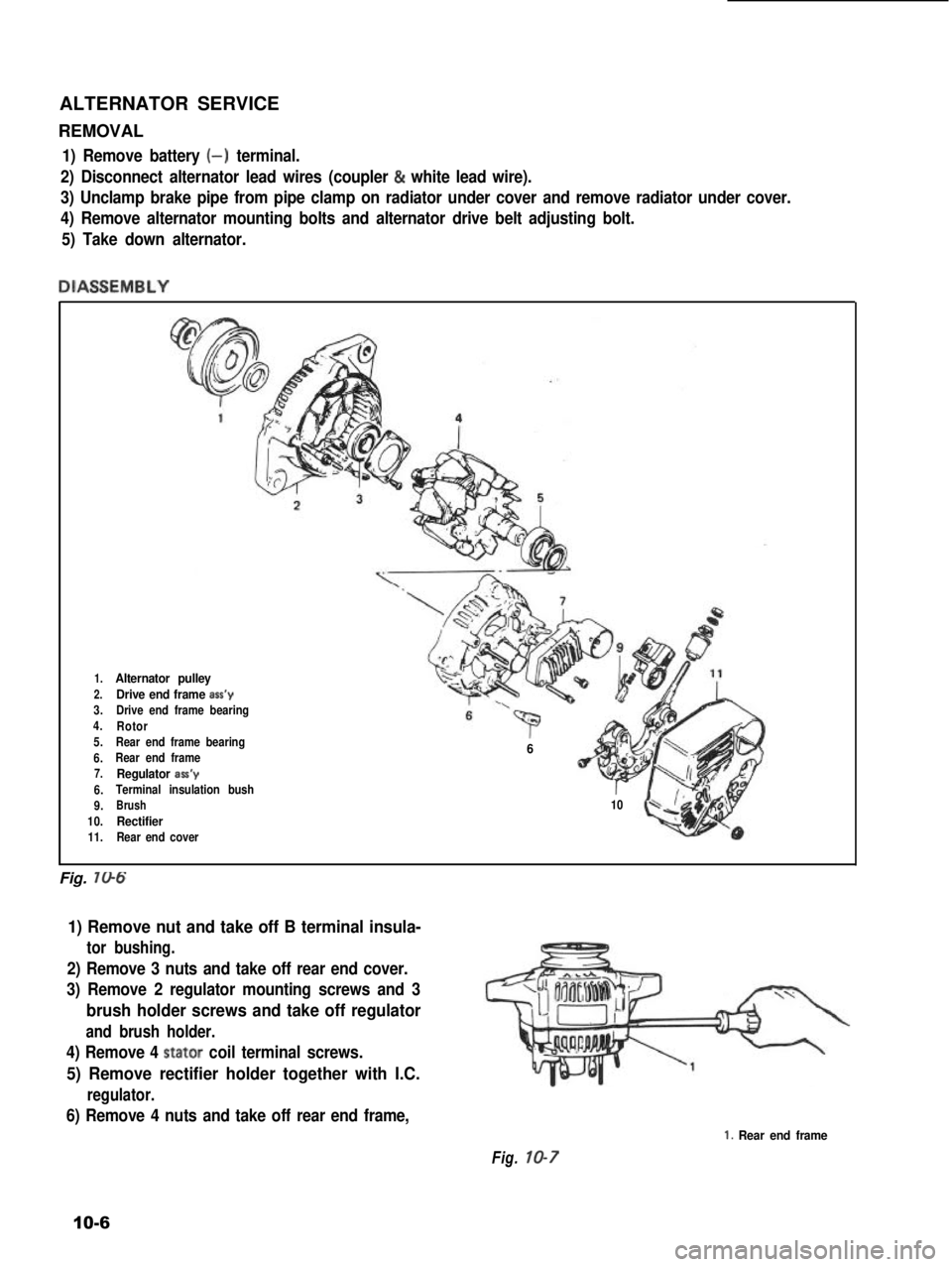
DIASSEMBLY
1.Alternator pulley
2.Drive end frame ass’y3.Drive end frame bearing4.Rotor5.Rear end frame bearing
6.Rear end frame7.Regulator aa’y
6.Terminal insulation bush
9.Brush
10.Rectifier11.Rear end cover
‘p” “i6
r10
Fig. 706
1) Remove nut and take off B terminal insula-
tor bushing.
2) Remove 3 nuts and take off rear end cover.
3) Remove 2 regulator mounting screws and 3
brush holder screws and take off regulator
and brush holder.
4) Remove 4 stator coil terminal screws.
5) Remove rectifier holder together with I.C.
regulator.
6) Remove 4 nuts and take off rear end frame,
Fig. 10-7
1. Rear end frame
10-6
Page 243 of 962
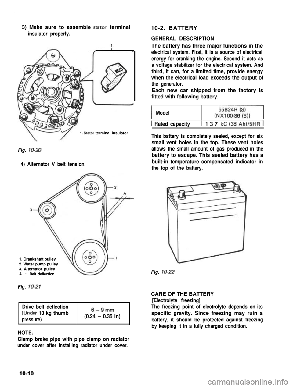
3) Make sure to assemble stator terminal
insulator properly.
10-2. BATTERY
1. Stator terminal insulator
Fig. lo-20
4) Alternator V belt tension.
1. Crankshaft pulley
2. Water pump pulley
3. Alternator pulley
A :Belt deflection
Fig. 1021
Drive belt deflection
(Under 10 kg thumb
pressure)
6-9mm
(0.24 - 0.35 in)
NOTE:
Clamp brake pipe with pipe clamp on radiator
under cover after installing radiator under cover.
GENERAL DESCRIPTION
The battery has three major functions in the
electrical system. First, it is a source of electrical
energy for cranking the engine. Second it acts as
a voltage stabilizer for the electrical system. And
third, it can, for a limited time, provide energy
when the electrical load exceeds the output of
the generator.
Each new car shipped from the factory is
fitted with following battery.
IModel55BzR=l(NXIOO-S6 6))
1 Rated capacityt 137 kC (38 Ah)/5HR j
This battery is completely sealed, except for six
small vent holes in the top. These vent holes
allows the small amount of gas produced in the
battery to escape. This sealed battery has a
built-in temperature compensated indicator in
the top of the battery.
Fig. lo-22
CARE OF THE BATTERY
[Electrolyte freezing]
The freezing point of electrolyte depends on its
specific gravity. Since freezing may ruin a
battery, it should be protected against freezing
by keeping it in a fully charged condition.
10-10
Page 382 of 962
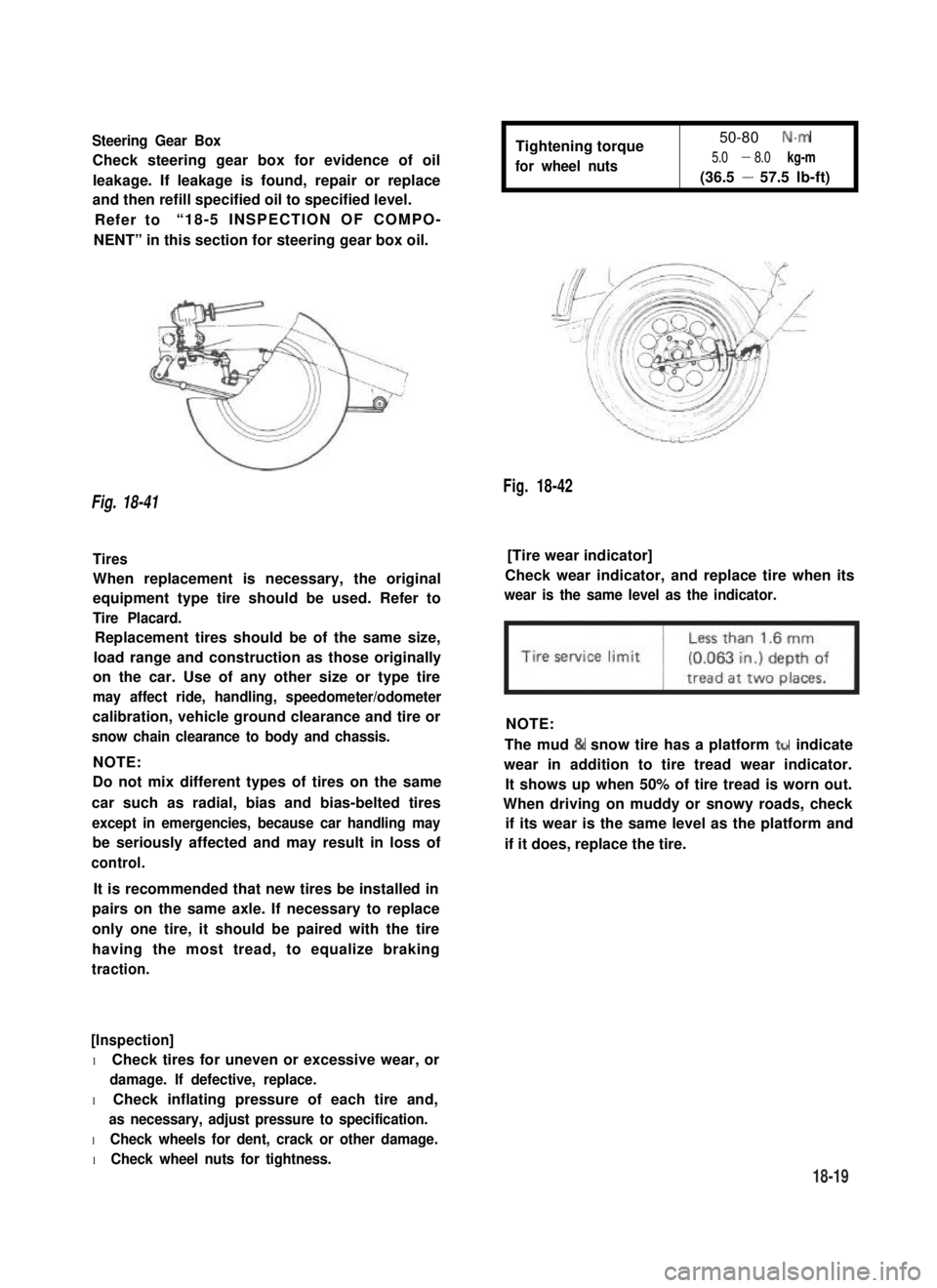
Steering Gear Box
Check steering gear box for evidence of oil
leakage. If leakage is found, repair or replace
and then refill specified oil to specified level.
Refer to“18-5 INSPECTION OF COMPO-
NENT” in this section for steering gear box oil.
Tightening torque
for wheel nuts
50-80 N.m
5.0 - 8.0 kg-m
(36.5 - 57.5 lb-ft)
Fig. 18-42
Fig. 18-41
Tires[Tire wear indicator]
When replacement is necessary, the original
equipment type tire should be used. Refer to
Tire Placard.
Check wear indicator, and replace tire when its
wear is the same level as the indicator.
Replacement tires should be of the same size,
load range and construction as those originally
on the car. Use of any other size or type tire
may affect ride, handling, speedometer/odometer
calibration, vehicle ground clearance and tire or
snow chain clearance to body and chassis.
NOTE:
NOTE:
Do not mix different types of tires on the same
car such as radial, bias and bias-belted tires
except in emergencies, because car handling may
be seriously affected and may result in loss of
control.
The mud & snow tire has a platform ttr indicate
wear in addition to tire tread wear indicator.
It shows up when 50% of tire tread is worn out.
When driving on muddy or snowy roads, check
if its wear is the same level as the platform and
if it does, replace the tire.
It is recommended that new tires be installed in
pairs on the same axle. If necessary to replace
only one tire, it should be paired with the tire
having the most tread, to equalize braking
traction.
[Inspection]
l Check tires for uneven or excessive wear, or
damage. If defective, replace.
l Check inflating pressure of each tire and,
as necessary, adjust pressure to specification.
l Check wheels for dent, crack or other damage.
l Check wheel nuts for tightness.
18-19
Page 448 of 962
21-1.COMBINATION METER..................................
21-2.HEAD LIGHT..........................................
21-3.TURN SIGNAL LIGHT AND HAZARD WARNING LIGHT.......
21-4.WINDSHIELD WIPER MOTOR.............................
21-5.WATER TEMPERATURE METER AND GAUGE...............
21-6.FUEL LEVEL METER AND GAUGE........................
21-7.BRAKE WARNING LAMP ...............................
21-8.OIL PRESSURE LAMP..................................
4 WHEEL DRIVE LAMP.................................
21-10. SEAT BELT WARNING LAMP/BUZZER.....................
...................
...~I-I
.....
21-14. .............................................
21-15. WIRING HARNESS ROUTING............................
21-16. WIRING DIAGRAM....................................
SECTION 21
BODY ELECTRICAL EQUIPMENT
CONTENTS
21-9.
21-11. MAIN SWITCH KEY WARNING BUZZER
21-12. ILUMINATION CONTROLLER..............................................
21-13. REAR DEFOGGER ( hard-top )......................................
FUSE BOX
21-2
21-4
21-7
21-9
21-11
21-12
21-13
21-14
21-15
21-15
21-16
21-16
21-16
21-18
21-19
21-22
21-1
Page 450 of 962
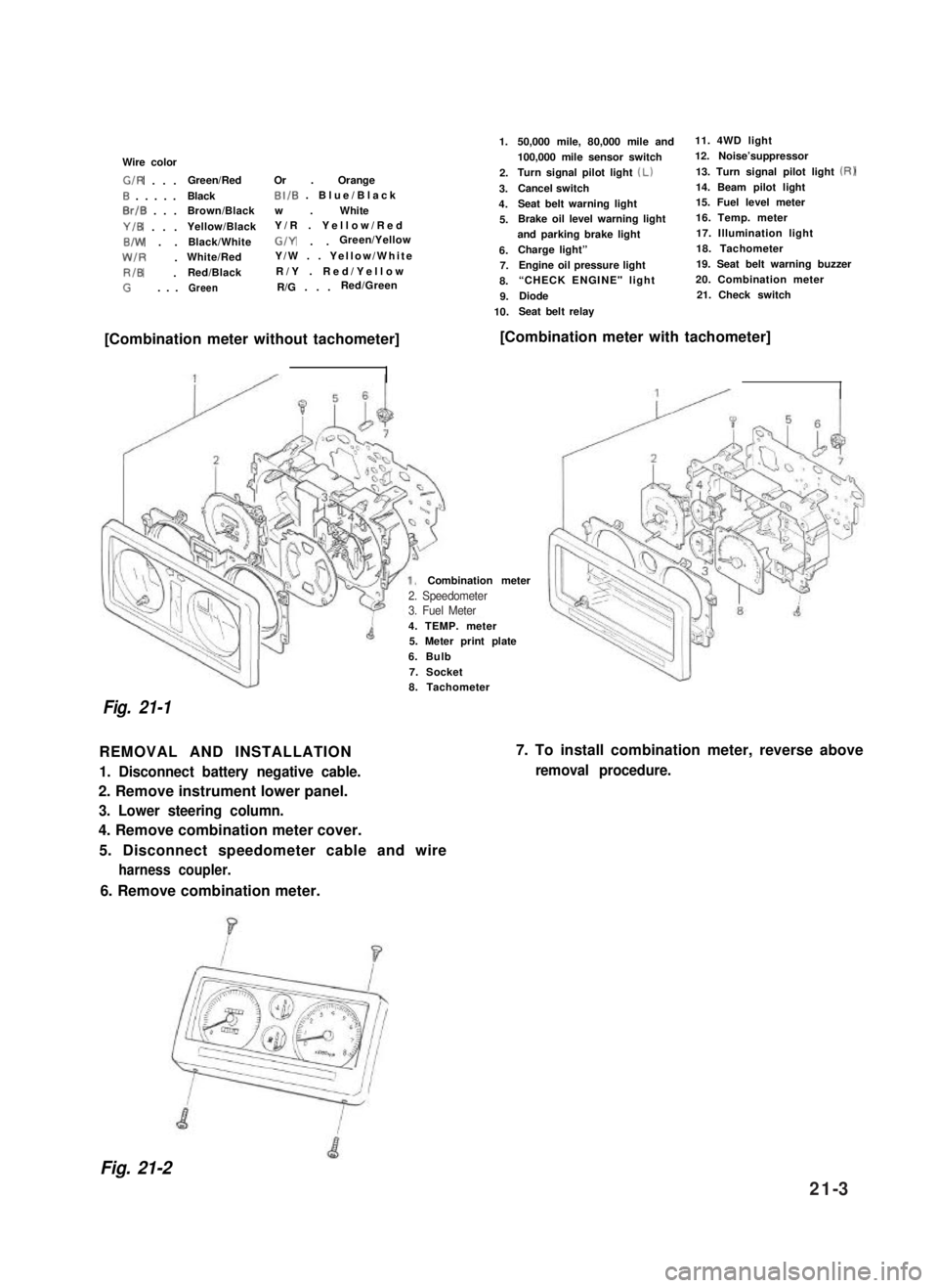
Wire color
G/R . . .Green/RedOr . Orange
0 . . . . .BlackBI/B . Blue/Black
0rlB . . .Brown/Blackw . White
Y/B . . .Yellow/BlackY/R . Yellow/Red
B/W . .Black/WhiteG/Y . .Green/Yellow
W/R .White/RedY/W . . Yellow/White
RIB .Red/BlackR/Y . Red/Yellow
G. . .GreenR/G . . .Red/Green
1.
2.
3.
4.
5.
6.7.
8.
9.
10.
50,000 mile, 80,000 mile and11. 4WD light
100,000 mile sensor switch12. Noise’suppressor
Turn signal pilot light (Lb13. Turn signal pilot light (RI
Cancel switch14. Beam pilot light
Seat belt warning light15. Fuel level meter
Brake oil level warning light16. Temp. meter
and parking brake light17. Illumination light
Charge light”18. Tachometer
Engine oil pressure light19. Seat belt warning buzzer
“CHECK ENGINE" light 20. Combination meter
Diode21. Check switch
Seat belt relay
[Combination meter without tachometer][Combination meter with tachometer]
4. TEMP. meter5. Meter print plate
6. Bulb
7. Socket
Combination meter
Fig. 21-1
8. Tachometer
REMOVAL AND INSTALLATION
1. Disconnect battery negative cable.
2. Remove instrument lower panel.
3. Lower steering column.
4. Remove combination meter cover.
5. Disconnect speedometer cable and wire
harness coupler.
7. To install combination meter, reverse above
removal procedure.
6. Remove combination meter.
Fig. 21-2
2. Speedometer3. Fuel Meter
21-3
Page 462 of 962
21-9. 4 WHEEL DRIVE LAMP21-10. SEAT BELT WARNING LAMP/
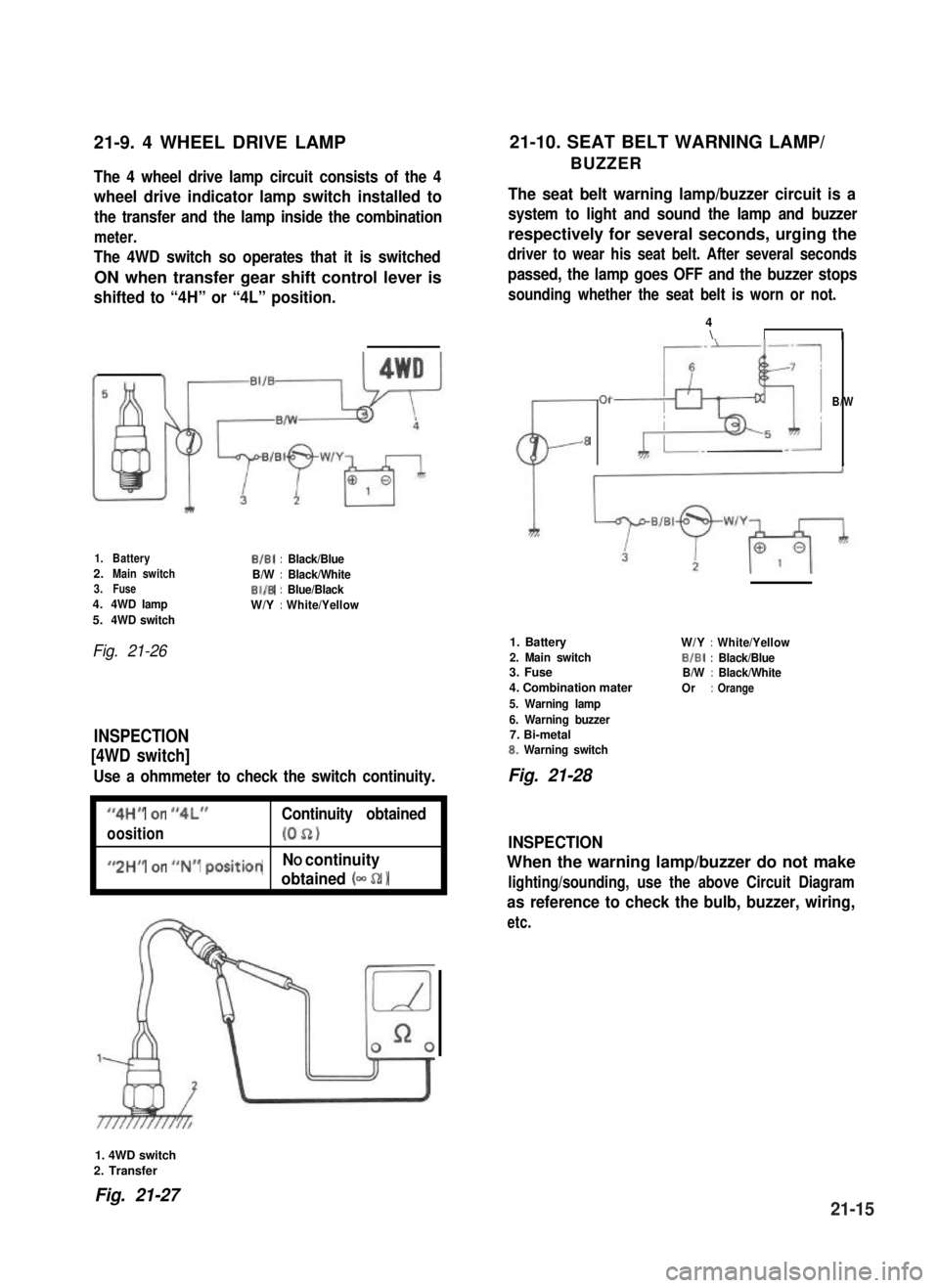
BUZZERThe 4 wheel drive lamp circuit consists of the 4
wheel drive indicator lamp switch installed to
the transfer and the lamp inside the combination
meter.
The 4WD switch so operates that it is switched
ON when transfer gear shift control lever is
shifted to “4H” or “4L” position.
The seat belt warning lamp/buzzer circuit is a
system to light and sound the lamp and buzzer
respectively for several seconds, urging the
driver to wear his seat belt. After several seconds
passed, the lamp goes OFF and the buzzer stops
sounding whether the seat belt is worn or not.
1.BatteryB/B1:Black/Blue2.Main switchB/W:Black/White3.FuseBI/B:Blue/Black4.4WD lampW/Y:White/Yellow5.4WD switch
Fig. 21-26
INSPECTION
[4WD switch]
Use a ohmmeter to check the switch continuity.
I
“4H” or “4L”Continuity obtained
oosition(052)I
I
#,2HM or ##N## positionNO continuity
obtained (- 52 1I
CL-
01
8
4\II
B/W
1. Battery
2. Main switch3. Fuse
4. Combination mater
5. Warning lamp
6. Warning buzzer7. Bi-metal8. Warning switch
W/Y:White/Yellow
BIBI:Black/BlueB/W:Black/White
Or:Orange
Fig. 21-28
INSPECTION
When the warning lamp/buzzer do not make
lighting/sounding, use the above Circuit Diagram
as reference to check the bulb, buzzer, wiring,
etc.
1. 4WD switch
2. Transfer
Fig. 21-2721-15