Page 67 of 962
6) Take down alternator and water pump
pulley.
Fig. 3-4,9 (A) Flywheel holder (Special tool
09924-17810)
Fig. 3-4-6
8) Remove outside cover on timing belt.
Fig. 3-4-7
7) Remove crankshaft pulley by removing 49) Loosen tensioner bolt and stud, and remove
pulley bolts, with special tool (A) hitched tobelt from crank timing belt pulley and cam-
flywheel so that crankshaft will not turn.shaft pulley after pushing up tensioner
The crank timing belt pulley bolt at theplate fully by finger as shown in Figure
center needs not to be loosened.3-4-l 1.
1.Crankshaft pulley
Fig. 3-4-8
2. Crankshaft pulley bolt
3.Crank timing belt pulley bolt
Fig. 3-4- 10
1.Timing belt2.Tensioner plate
3.Tensioner boltFig.3-4-114.Tensioner stud
3-10
Page 68 of 962
10) Remove timing belt tensioner, tensioner
plate, and tensioner spring.
11) Remove camshaft timing belt pulley by lock-
ing camshaft (insert general rod into the cam-
shaft hole) as shown below.
13) Remove crankshaft timing belt pulley key.
14) Remove timing belt inside cover.
Fig. 3-4- 14
15) Remove water pump.
1.Wrench2.Camshaft timing belt pulley
3. Timing belt inside cover4.Generalrod
Fig.3412
12) Using flywheel holder (A) (Special tool),
remove crankshaft timing belt pulley bolt,
pulley and timing belt guide with crank-
shaft locked.
Fig. 3-4- 15
16) Remove exhaust manifold cover.
17) Take off exhaust manifold and its gasket.
Fig. 3-4-13
1.Crankshaft timing belt pulley2. Pulley bolt3. Timing belt guide
Fig. 3-4- 16
3-11
Page 92 of 962
3-6. ENGINE REASSEMBLY
NOTE:
l All parts to be used in reassembly must be
perfectly clean.
l Oil sliding and rubbing surfaces of engine
parts just before using them in reassembly.
Use engine oil (Refer to page l-8).
l Have liquid packing ready for use. SUZUKI
BOND NO. 1215 is specified for it. Use it
wherever its use is specified in order to
ensure leak-free (oil and water) workmanship
of reassembly.
l There are many running clearances. During
the course of engine reassembly, be sure to
check these clearances, one after another,
as they form.
l Gaskets, “0” rings and similar sealing mem-
bers must be in perfect condition. For these
members, use replacement parts in stock.
l Tightening torque is specified for impor-
tant fasteners - mainly bolts and nuts -of
the engine and other components. Use torque
wrenches and constantly refer to the specified
values given on p. 3-58.
l Do not disregard match marks provided on
parts. Some of them are those given at the
time of disassembly.
l There are many sets of parts. Crankshaft
bearings, connecting rods, pistons, etc., are
in combination sets. Do not disturb such
combinations and make sure that each part
goes back to where it came from.
Engine reassembly is the reverse of engine disas-
sembly as far as sequence is concerned, but
there are many reassembling steps that involve
measures necessary for restoring engine as close
to factory-assembled condition as possible. Only
those steps will be dealt with here.
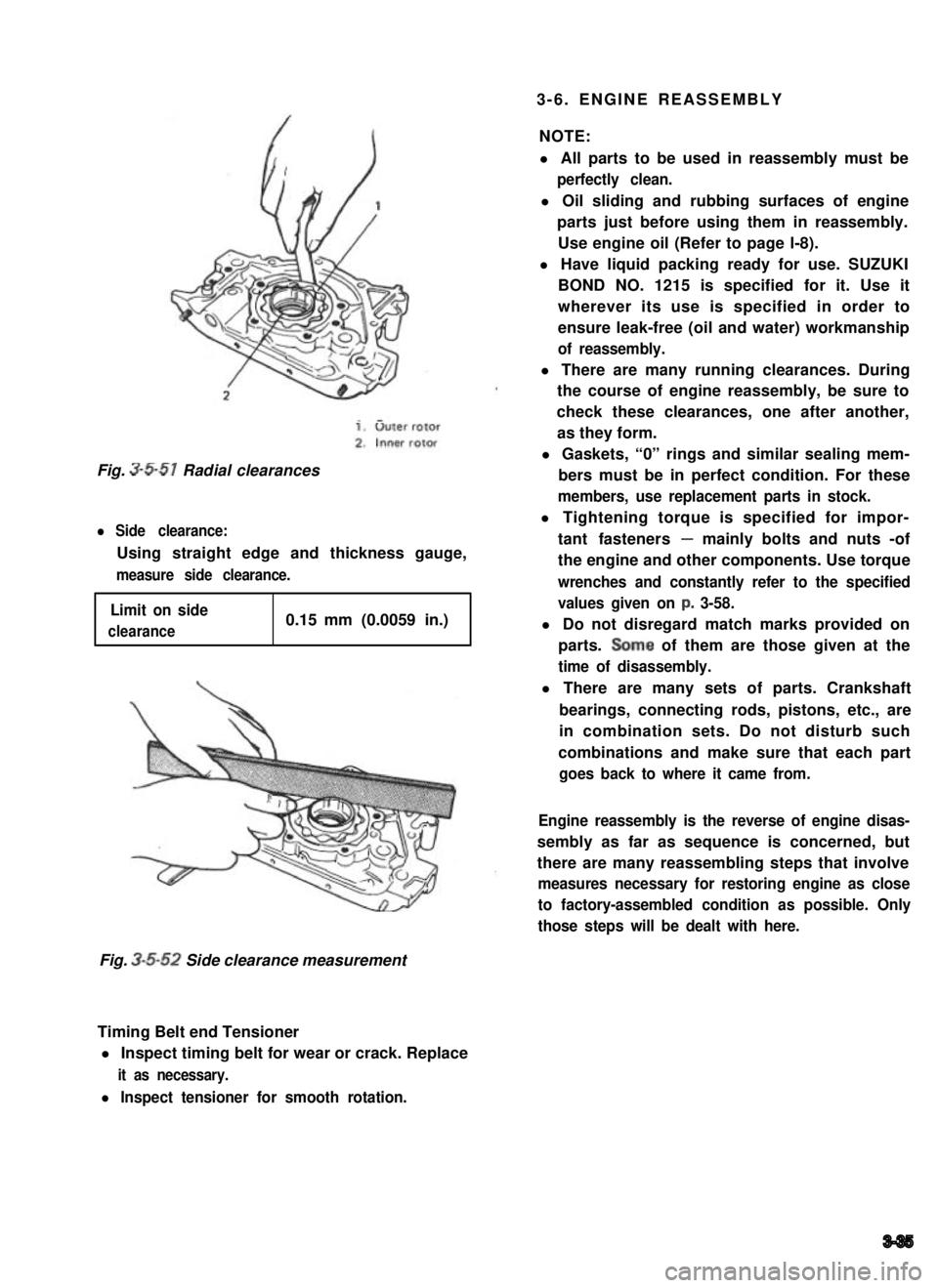
Fig. 3-5-51 Radial clearances
l Side clearance:
Using straight edge and thickness gauge,
measure side clearance.
Limit on side
clearance0.15 mm (0.0059 in.)
Fig. 3-5-52 Side clearance measurement
Timing Belt end Tensioner
l Inspect timing belt for wear or crack. Replace
it as necessary.
l Inspect tensioner for smooth rotation.
3-35
Page 105 of 962
Timing Belt Inside Cover, Belt Pulleys,
Tensioner, Timing Belt and Outside Cover
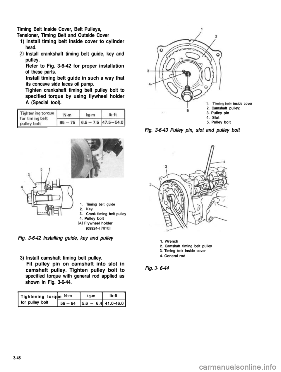
1) install timing belt inside cover to cylinder
head.
2) Install crankshaft timing belt guide, key and
pulley.
Refer to Fig. 3-6-42 for proper installation
of these parts.
Install timing belt guide in such a way that
its concave side faces oil pump.
Tighten crankshaft timing belt pulley bolt to
specified torque by using flywheel holder
A (Special tool).
1.
2.3.
Timing belt guide
KeyCrank timing belt pulley4. Pulley bolt
(A) Flywheel holder
(09924-I 7810)
Fig. 3-6-42 Installing guide, key and pulley
3) Install camshaft timing belt pulley.
Fit pulley pin on camshaft into slot in
camshaft pulley. Tighten pulley bolt to
specified torque with general rod applied as
shown in Fig. 3-6-44.
inside cover2. Camshaft pulley:
3. Pulley pin4. Slot5. Pulley bolt
Fig. 3-6-43 Pulley pin, slot and pulley bolt
1. Wrench
2. Camshaft timing belt pulley3. Timing belt inside cover
4. General rod
Fig. 3- 6-44
Tightening torque N-mkg-mlb-ft
for pulley bolt56 - 645.6 - 6.4 41.0-46.0
3-48
Page 106 of 962
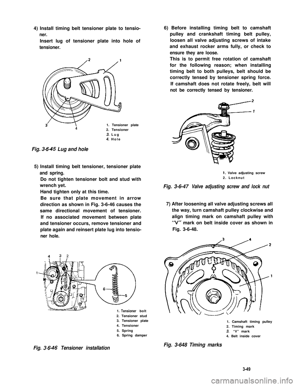
4) Install timing belt tensioner plate to tensio-
ner.
Insert lug of tensioner plate into hole of
tensioner.
3w1. Tensioner plate42. Tensioner
3. Lug4. Hole
Fig. 3-645 Lug and hole
5) Install timing belt tensioner, tensioner plate
and spring.
Do not tighten tensioner bolt and stud with
wrench yet.
Hand tighten only at this time.
Be sure that plate movement in arrow
direction as shown in Fig. 3-6-46 causes the
same directional movement of tensioner.
If no associated movement between plate
and tensioner occurs, remove tensioner and
plate again and reinsert plate lug into tensio-
ner hole.
1. bolt
2. Tensioner stud3. Tensioner plate
4. Tensioner
5. Spring6. Spring damper
Fig. 3-646 Tensioner installation
6) Before installing timing belt to camshaft
pulley and crankshaft timing belt pulley,
loosen all valve adjusting screws of intake
and exhaust rocker arms fully, or check to
ensure they are loose.
This is to permit free rotation of camshaft
for the following reason; when installing
timing belt to both pulleys, belt should be
correctly tensed by tensioner spring force.
If camshaft does not rotate freely, belt will
not be correctly tensed by tensioner.
1. Valve adjusting screw
2. Locknut
Fig. 3-6-47Valve adjusting screw and lock nut
7) After loosening all valve adjusting screws all
the way, turn camshaft pulley clockwise and
align timing mark on camshaft pulley with
“V” mark on belt inside cover as shown in
Fig. 3-6-48.
1. Camshaft timing pulley
2. Timing mark
3.“V” mark4. Belt inside cover
Fig. 3-648 Timing marks
3-49
Tensioner
Page 107 of 962
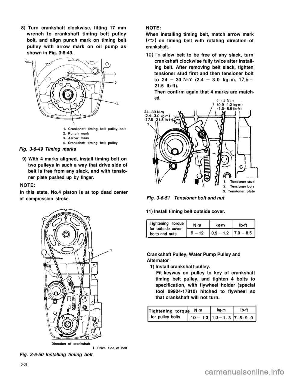
8) Turn crankshaft clockwise, fitting 17 mm
wrench to crankshaft timing belt pulley
bolt, and align punch mark on timing belt
pulley with arrow mark on oil pump as
shown in Fig. 3-6-49.
1. Crankshaft timing belt pulley bolt2. Punch mark3. Arrow mark
4. Crankshaft timing belt pulley
Fig. 3-6-49 Timing marks
9) With 4 marks aligned, install timing belt on
two pulleys in such a way that drive side of
belt is free from any slack, and with tensio-
ner plate pushed up by finger.
NOTE:
In this state, No.4 piston is at top dead center
of compression stroke.
NOTE:
When installing timing belt, match arrow mark
(+I on timing belt with rotating direction of
crankshaft.
10)To allow belt to be free of any slack, turn
crankshaft clockwise fully twice after install-
ing belt. After removing belt slack, tighten
tensioner stud first and then tensioner bolt
to 24 - 30 N.m (2.4 - 3.0 kg-m, 17,5 -
21.5 lb-ft).
Then confirm again that 4 marks are match-
ed.9-12 N-m
3. Tensioner plate
Fig. 3-6-51Tensioner bolt and nut
11) Install timing belt outside cover.
Tightening torque
for outside coverN.mkmlb-ft
bolts and nuts9- 120.9 - 1.27.0 - 8.5
Crankshaft Pulley, Water Pump Pulley and
Alternator
1) Install crankshaft pulley.
Fit keyway on pulley to key of crankshaft
timing belt pulley, and tighten 4 bolts to
specification, with flywheel holder (special
tool 09924-17810) hitched to flywheel so
that crankshaft will not turn.
Tightening torque N.mkg-mlb-ft
for pulley boltslo- 13 1.3 7.5-9.0*
Direction of crankshaft1. Drive side of belt
Fig. 3-6-50 Installing timing belt
3-50
Page 108 of 962
-1. Key
‘32. Crankshaft pulley3. Pulley bolt
Fig. 3-6-52 Installing crankshaft pulley
2) Install alternator assembly.
Tighten alternator ass’y securing bolts (3pcs)
only to the extent to allow alternator to be
moved by hand. Don’t torque them tight.
NOTE:
Adjust water pump belt tension to specification
upon completion of installing engine ass’y to
body and then cooling fan and water pump
pulley. Make sure to refer to p. 1-5 of this
manual for adjusting procedure.
Distributor Case
1) Install distributor case O-ring to cylinder
head.
2) Install distributor case.
3) Tighten bolts to specified torque.
Tightening torque N.mkg-mlb-ft
forcasebolts8-120.8-1.26.0-8.5
Fig. 3-6-53
Fuel Pump
Install fuel pump rod, gasket and fuel pump to
cylinder head.
Apply engine oil to rod @ before installation.
Use new gasket.
Fig. 3-6-54 Fuel pump rod installation
case with about 3Occ (1.02/1.05 US/Imp
3-51
Page 110 of 962
3-7. ENGINE INSTALLATION
1) Lower engine with transmission into vehicle,
but do not remove lifting device.
2) Tighten engine mounting bracket bolts
(right and left) and transmission mounting
bolts to specification. Refer to p. 3-58.
3) Remove lifting device.
4) Reverse removal procedures for installation
of remainder.
5) Adjust accelerator cable play and clutch
cable play.
6) Connect vacuum hoses securely. Refer to
section 5 “EMISSION CONTROL SYSTEM”
for correct connection.
7) Connect wire harnesses and couplers secure-
IY.
8) Tighten bolts and nuts to specified torque.
For individual specification, refer to each
section.
9) Fill specified amount of specified trans-
mission oil and engine oil. For the detail,
refer to SECTION 1 PERIODIC MAINTE-
NANCE SERVICE of this manual.
10) After adjusting water pump belt tension to
specification, fill specified amount of engine
cooling water.
11) Before starting engine, check again to ensure
that all parts once disassembled or discon-
nected are back in place securely.
12)Start engine and check ignition timing. If
it is not to specified timing, adjust it, referr-
ing to SECTION 8 of this manual.
13) After engine is started, check for oil leak,
abnormal noise and other malcondition.
Also, check each part for operation.
3-8. ENGINE MAINTENANCE SERVICE
Fan Belt
Adjust belt tension as outlined in SECTION 6
ENGINE COOLING SYSTEM (p. 6-10).
Ignition Timing
Refer to IGNITION TIMING, Page 8-9.
Carburetor
fidjustments to be made are detailed in SEC-
TION 4 (p. 4-19).
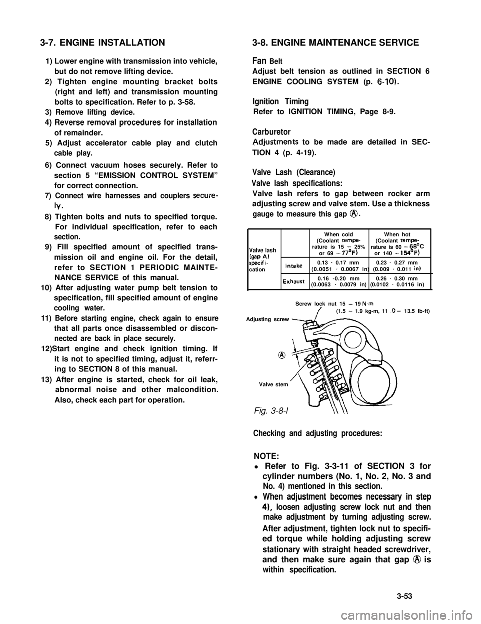
Valve Lash (Clearance)
Valve lash specifications:
Valve lash refers to gap between rocker arm
adjusting screw and valve stem. Use a thickness
gauge to measure this gap @.
When coldWhen hot(Coolant tempe-(Coolant tempa-
Valve lashrature is 15 - 25%rature is 60 - 66’C
(gap A)or 69 - 77’F)or 140 - 154’F)
specif i-0.13 - 0.17 mm0.23 - 0.27 mmcationIntake(0.0051 - 0.0067 in) (0.009 - 0.011 in)
Exhaust0.16 -0.20 mm0.26 - 0.30 mm(0.0063 - 0.0079 in) (0.0102 - 0.0116 in)
Screw lock nut 15 - 19 N.m(1.5 - 1.9 kg-m, 11 .O - 13.5 lb-ft)
Adjusting screw
8
Valve stem
Fig. 3-8-l
Checking and adjusting procedures:
NOTE:
l Refer to Fig. 3-3-11 of SECTION 3 for
cylinder numbers (No. 1, No. 2, No. 3 and
No. 4) mentioned in this section.
l When adjustment becomes necessary in step
4), loosen adjusting screw lock nut and then
make adjustment by turning adjusting screw.
After adjustment, tighten lock nut to specifi-
ed torque while holding adjusting screw
stationary with straight headed screwdriver,
and then make sure again that gap @ is
within specification.
3-53