1987 SUZUKI GRAND VITARA width
[x] Cancel search: widthPage 78 of 962
l Check end face of each valve stem for wear.
This face meets rocker arm intermittently
‘in operation, and might become concaved or
otherwise irregular. As necessary, smoothen
the end face with an oil stone and, if this
grinding removes the end stock by as much as
0.5 mm (0.0196 in.) (as measured from the
original face), replace the valve.
Limit on stock allowance0.5 mm
of valve stem end face(0.0196 in.)
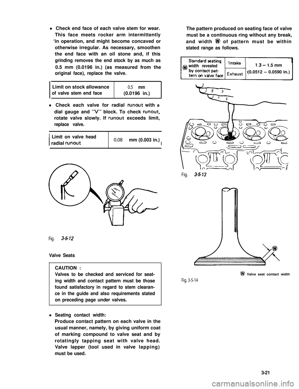
l Check each valve for radial runout with a
dial gauge and “V” block. To check runout,
rotate valve slowly. If runout exceeds limit,
replace valve.
I
Limit on valve head
radial runout0.08 mm (0.003 in.)I
Fig. 3-612
Valve Seats
CAUTION :
Valves to be checked and serviced for seat-
ing width and contact pattern must be those
found satisfactory in regard to stem clearan-
ce in the guide and also requirements stated
on preceding page under valves.
l Seating contact width:
Produce contact pattern on each valve in the
usual manner, namely, by giving uniform coat
of marking compound to valve seat and by
rotatingly tapping seat with valve head.
Valve lapper (tool used in valve lapping)
must be used.
The pattern produced on seating face of valve
must be a continuous ring without any break,
and width 6@ of pattern must be within
stated range as follows.
width revealed1.3- 1.5 mm
(0.0512 - 0.0590 in.)
Fig. 3-5-13
Fig. 3-5-14
@ Valve seat contact width
3-21
Page 79 of 962
l Valve seat repair:
Valve seat not producing uniform contact
with its valve or showing width @ of seating
contact that is off the specified range must be
repaired by regrinding or by cutting and
regrinding and finished by lapping.
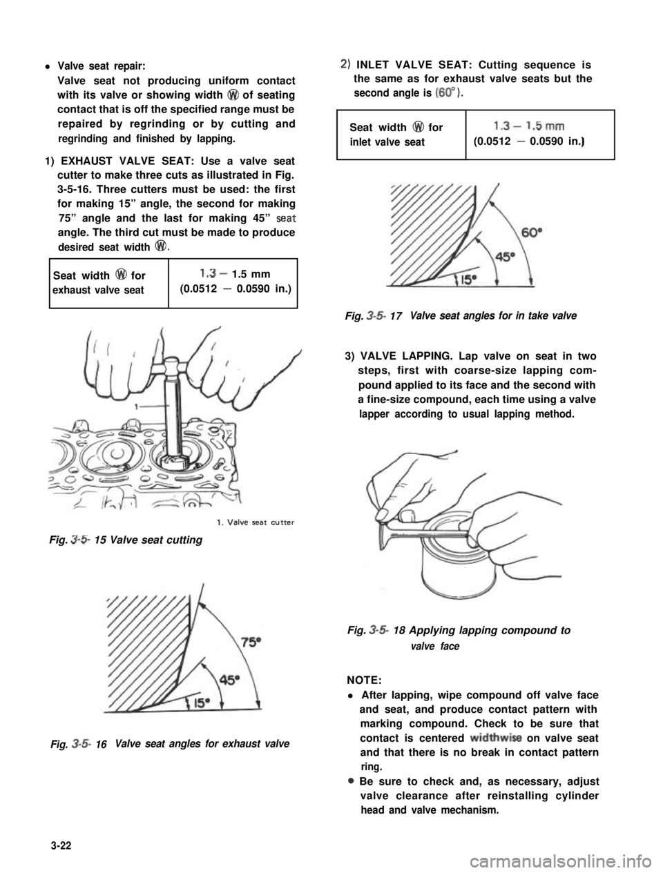
1) EXHAUST VALVE SEAT: Use a valve seat
cutter to make three cuts as illustrated in Fig.
3-5-16. Three cutters must be used: the first
for making 15” angle, the second for making
75” angle and the last for making 45” Seat
angle. The third cut must be made to produce
desired seat width @I!).
Seat width @ for1.3- 1.5 mm
exhaust valve seat(0.0512 - 0.0590 in.)
1. Valve seat CUtter
Fig. 3-S 15 Valve seat cutting
Fig. 3-5- 16Valve seat angles for exhaust valve
2) INLET VALVE SEAT: Cutting sequence is
the same as for exhaust valve seats but the
second angle is (60” ).
Seat width @I for1.3- 1.5mm
inlet valve seatI(0.0512 - 0.0590 in.)
Fig. 3-5- 17Valve seat angles for in take valve
3) VALVE LAPPING. Lap valve on seat in two
steps, first with coarse-size lapping com-
pound applied to its face and the second with
a fine-size compound, each time using a valve
lapper according to usual lapping method.
Fig. 3-5- 18 Applying lapping compound to
valve face
NOTE:
l After lapping, wipe compound off valve face
and seat, and produce contact pattern with
marking compound. Check to be sure that
contact is centered widthwise on valve seat
and that there is no break in contact pattern
ring.
a Be sure to check and, as necessary, adjust
valve clearance after reinstalling cylinder
head and valve mechanism.
3-22
Page 84 of 962
l Connecting rod alignment:
Mount connecting rod on aligner to check
it for bow and twist and, if either limit is
exceeded, replace it.
Limit on bow0.05 mm (0.0020 in.)
ILimit on twist) 0.10 mm (0.0039 in.) 1
Crank Pin and Connecting Rod Bearings
l Inspect crank pin for uneven wear or damage.
Measure crank pin for out-of-round or taper
with a micrometer. If crank pin is damaged,
or out-of-round or taper is out of limit,
replace crankshaft or regrind crank pin to
undersize and use undersize bearing.
I
Connecting
rod bearing sizeCrank pin diameterI
IStandard41.982 - 42.000 mm
(1.6529 - 1.6535 in.)I
0.25 mm (0.0098 in.)41.732 - 41.750 mm
undersize(1.6430 - 1.6437 in.)
Out-of-round and
taper limit0.01 mm (0.0004 in.)
l Rod bearing:
Inspect bearing shells for signs of fusion,
pitting, burn or flaking and observe contact
pattern. Bearing shells found in defective
condition must be replaced.
Two kinds of rod bearing are available;
standard size bearing and 0.25 mm under-
size bearing. To distinguish them, 0.25 mm
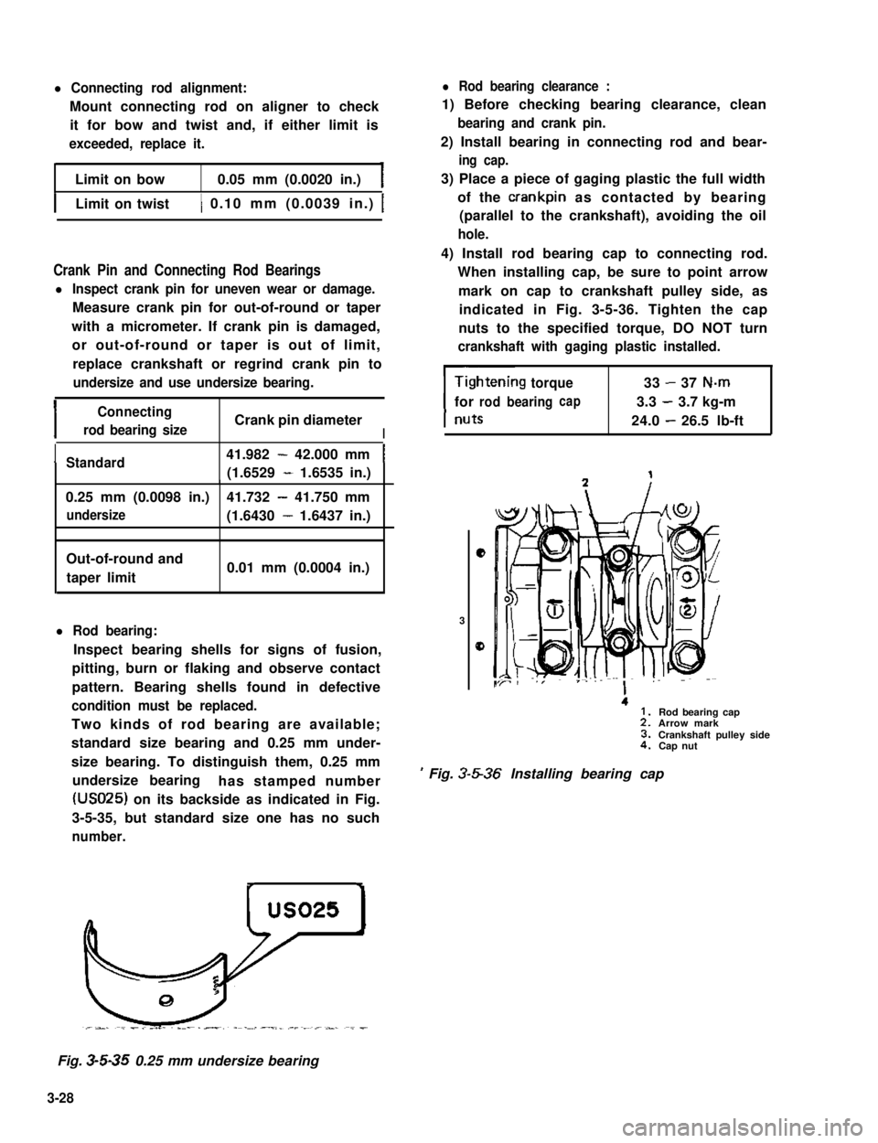
undersize bearinghas stamped number
(USO25) on its backside as indicated in Fig.
3-5-35, but standard size one has no such
number.
l Rod bearing clearance :
1) Before checking bearing clearance, clean
bearing and crank pin.
2) Install bearing in connecting rod and bear-
ing cap.
3) Place a piece of gaging plastic the full width
of the crankpin as contacted by bearing
(parallel to the crankshaft), avoiding the oil
hole.
4) Install rod bearing cap to connecting rod.
When installing cap, be sure to point arrow
mark on cap to crankshaft pulley side, as
indicated in Fig. 3-5-36. Tighten the cap
nuts to the specified torque, DO NOT turn
crankshaft with gaging plastic installed.
torque33-37 N-m
forrodbearingcap3.3-3.7 kg-m
24.0-26.5 lb-ft
e
3
0
.
’ Fig. 3-5-36 Installing bearing cap
Rod bearing capArrow markCrankshaft pulley sideCap nut
Fig. 3-5-35 0.25 mm undersize bearing
3-28
Page 85 of 962
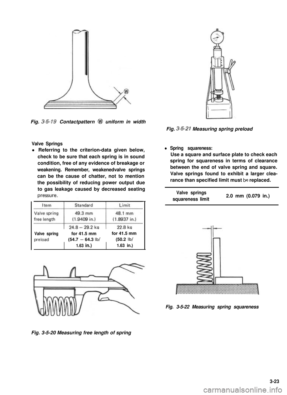
Fig. 3-5-19 Contactpattern @ uniform in width
Valve Springs
l Referring to the criterion-data given below,
check to be sure that each spring is in sound
condition, free of any evidence of breakage or
weakening. Remember, weakenedvalve springs
can be the cause of chatter, not to mention
the possibility of reducing power output due
to gas leakage caused by decreased seating
Valve springfor 41.5 mmfor 41.5 mm
preload(54.7 - 64.3 lb/(50.2 lb/
1.63 in.)1.63 in.)
Fig. 3-5-21 Measuring spring preload
l Spring squareness:
Use a square and surface plate to check each
spring for squareness in terms of clearance
between the end of valve spring and square.
Valve springs found to exhibit a larger clea-
rance than specified limit must be replaced.
Valve springs
squareness limit2.0 mm (0.079 in.)
Fig. 3-5-22 Measuring spring squareness
Fig. 3-5-20 Measuring free length of spring
3-23
Page 86 of 962
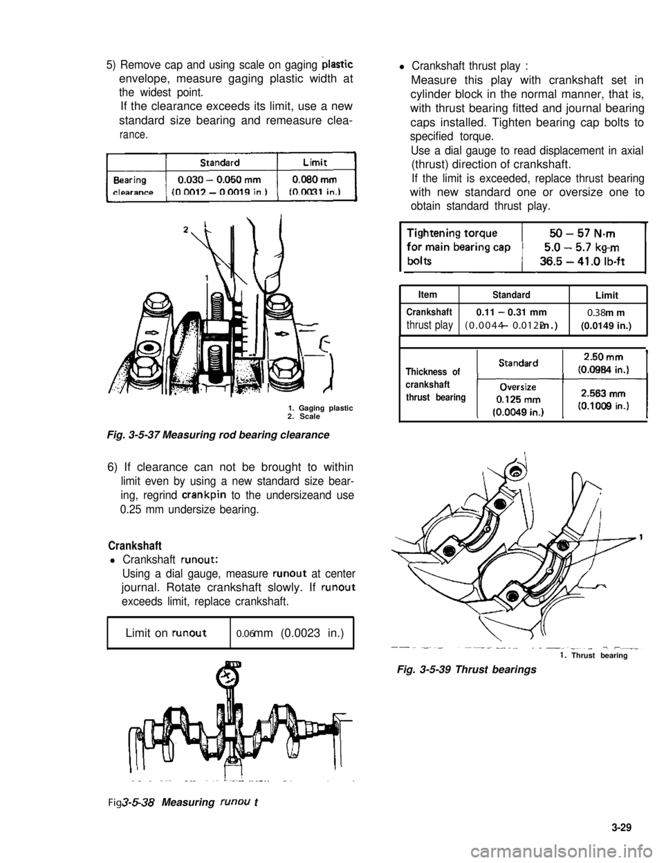
c5) Remove cap and using scale on gaging bIastic
envelope, measure gaging plastic width at
the widest point.
If the clearance exceeds its limit, use a new
standard size bearing and remeasure clea-
rance.
1. Gaging plastic2. Scale
Fig. 3-5-37 Measuring rod bearing clearance
6) If clearance can not be brought to within
limit even by using a new standard size bear-
ing, regrind crankpin to the undersizeand use
0.25 mm undersize bearing.
Crankshaft
l Crankshaft runout:
Using a dial gauge, measure runout at center
journal. Rotate crankshaft slowly. If runout
exceeds limit, replace crankshaft.
Limit on runout0.06 mm (0.0023 in.)
l Crankshaft thrust play :
Measure this play with crankshaft set in
cylinder block in the normal manner, that is,
with thrust bearing fitted and journal bearing
caps installed. Tighten bearing cap bolts to
specified torque.
Use a dial gauge to read displacement in axial
(thrust) direction of crankshaft.
If the limit is exceeded, replace thrust bearing
with new standard one or oversize one to
obtain standard thrust play.
ItemStandardLimit
Crankshaft0.11 - 0.31 mm0.38 mm
thrust play(0.0044 - 0.0122 in.)(0.0149 in.)
-.Thickness of
crankshaft
thrust bearing
1, Thrust bearing
Fig. 3-5-39 Thrust bearings
Fig. 3-5-38 Measuring runou t
3-29
Page 88 of 962
inspect:
Check bearings for pitting, scratches, wear or
damage. If any malcondition is found, replace
both upper and lower halves. Never replace one
half without replacing the other half.
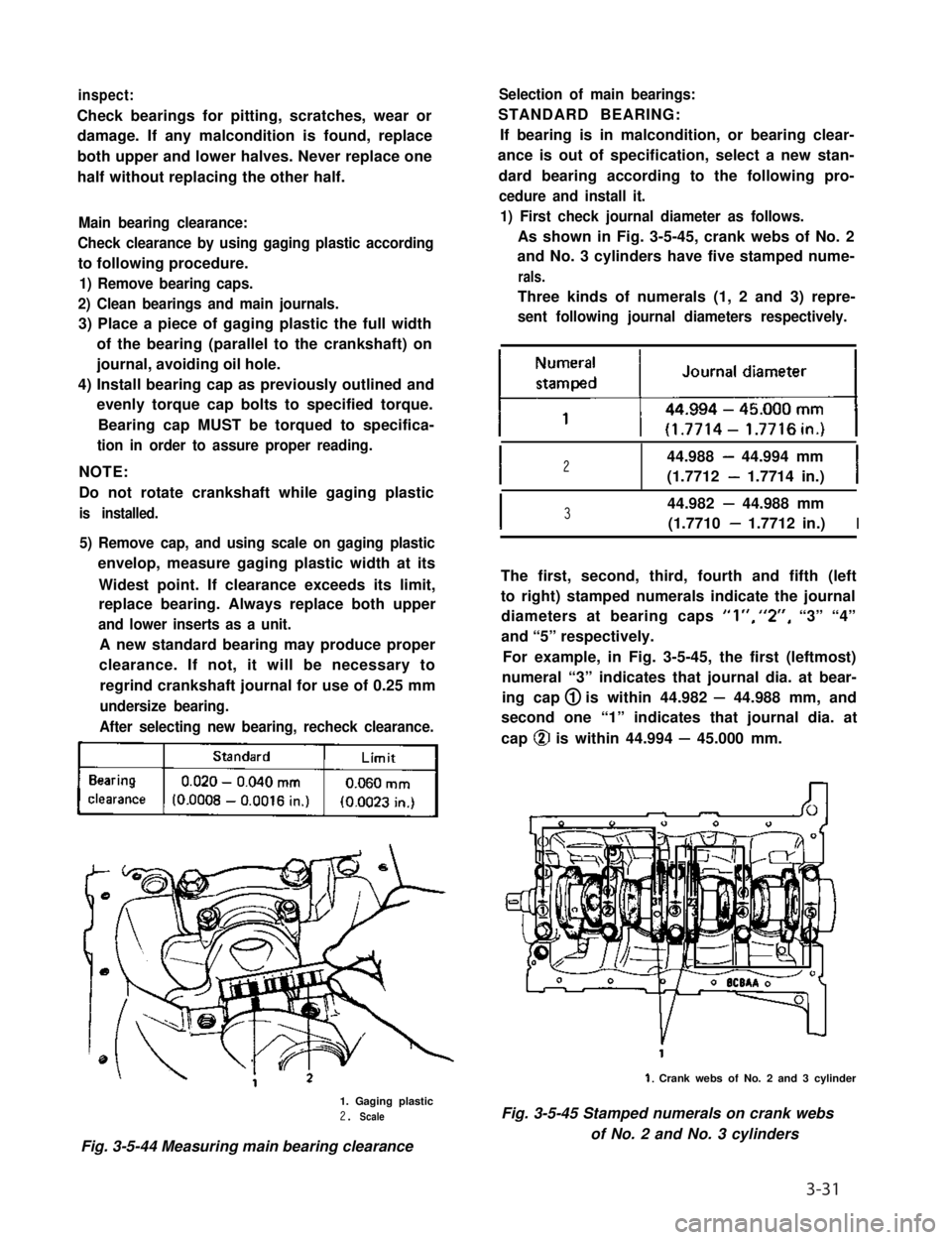
Main bearing clearance:
Check clearance by using gaging plastic according
to following procedure.
1) Remove bearing caps.
2) Clean bearings and main journals.
3) Place a piece of gaging plastic the full width
of the bearing (parallel to the crankshaft) on
journal, avoiding oil hole.
4) Install bearing cap as previously outlined and
evenly torque cap bolts to specified torque.
Bearing cap MUST be torqued to specifica-
tion in order to assure proper reading.
NOTE:
Do not rotate crankshaft while gaging plastic
is installed.
5) Remove cap, and using scale on gaging plastic
envelop, measure gaging plastic width at its
Widest point. If clearance exceeds its limit,
replace bearing. Always replace both upper
and lower inserts as a unit.
A new standard bearing may produce proper
clearance. If not, it will be necessary to
regrind crankshaft journal for use of 0.25 mm
undersize bearing.
After selecting new bearing, recheck clearance.
kj
1. Gaging plastic2. Scale
Fig. 3-5-44 Measuring main bearing clearance
Selection of main bearings:
STANDARD BEARING:
If bearing is in malcondition, or bearing clear-
ance is out of specification, select a new stan-
dard bearing according to the following pro-
cedure and install it.
1) First check journal diameter as follows.
As shown in Fig. 3-5-45, crank webs of No. 2
and No. 3 cylinders have five stamped nume-
rals.
Three kinds of numerals (1, 2 and 3) repre-
sent following journal diameters respectively.
I244.988 - 44.994 mm
(1.7712 - 1.7714 in.)I
I344.982 - 44.988 mm
(1.7710 - 1.7712 in.)I
The first, second, third, fourth and fifth (left
to right) stamped numerals indicate the journal
diameters at bearing caps “l”, “2”, “3” “4”
and “5” respectively.
For example, in Fig. 3-5-45, the first (leftmost)
numeral “3” indicates that journal dia. at bear-
ing cap 1 is within 44.982 - 44.988 mm, and
second one “1” indicates that journal dia. at
cap @ is within 44.994 - 45.000 mm.
1. Crank webs of No. 2 and 3 cylinder
Fig. 3-5-45 Stamped numerals on crank webs
of No. 2 and No. 3 cylinders
3-31
Page 275 of 962
By friction between the gear cone and ring
cone (internal), the ring begins to rotate but
is copposed by the hub because of keys. In
other words, the ring is at this time twisted,
while the sleeve is advancing further to push the
ring fully against the gear cone, Since the
ring is unable to slide along any further, the
sleeve lets go off the keys and rides over to the
ring. At this moment, the initial contact be-
tween the chamfered ends of teeth of the ring
and those of internal teeth of the sleeve occurs.
This contact is such that the internal teeth of
the sleeve align themselves to those of the ring.
When the sleeve advances and slides into the
ring, the ring will be rotating nearly with the
speed of the gear, so that the sleeve is enabled
smoothly to slide over into the clutch teeth of
the gear.
The initial contactor mesh between sleeve and
ring is determined by the widths of key and slot
or, in other words, the key clearance in the
slot, and is prescribed to extend at least a
third (l/3) of the chamfer.
With the synchronizer properly assembled on
the shaft, push in and twist each synchronizer to
see if one-third mesh occurs or not; if not, it
means that the overall wear (which is the sum of
wears of slots, keys and chamfered tooth ends)
is excessive and, in such a case, the entire
synchronizer assembly must be replaced.
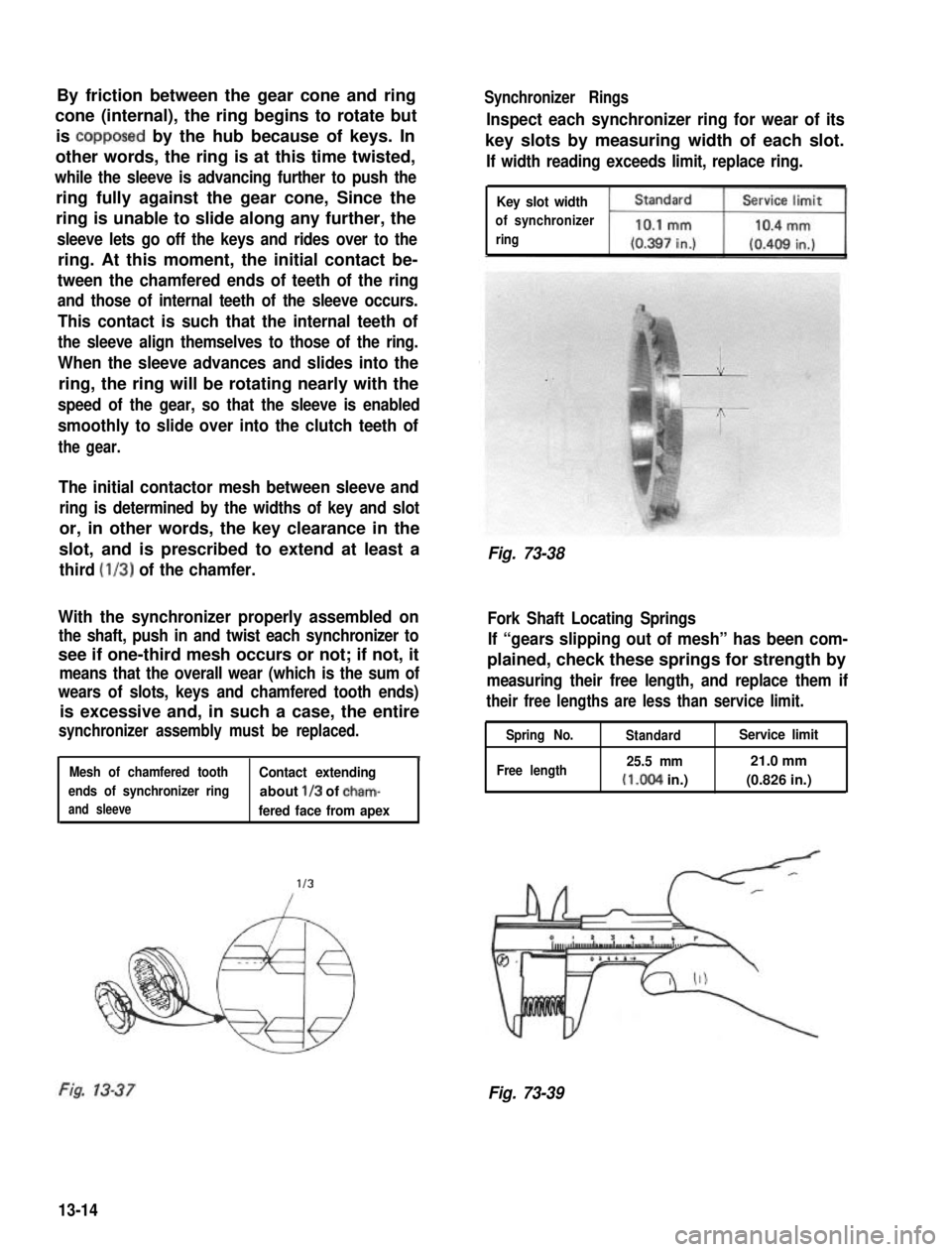
1Mesh of chamfered toothContact extending
ends of synchronizer ringabout l/3 of cham-
and sleevefered face from apex
l/3
Synchronizer Rings
Inspect each synchronizer ring for wear of its
key slots by measuring width of each slot.
If width reading exceeds limit, replace ring.
Key slot width
of synchronizer
ring
Fig. 73-38
Fork Shaft Locating Springs
If “gears slipping out of mesh” has been com-
plained, check these springs for strength by
measuring their free length, and replace them if
their free lengths are less than service limit.
Spring No.
Free length
StandardService limit
25.5 mm21.0 mm
(I.004 in.)(0.826 in.)
Fig. 73-39
13-14
Page 383 of 962
![SUZUKI GRAND VITARA 1987 Service Repair Manual Fig. 18-43 @ Tire tread wear indicator
@ Wear indicating platform
[ Inflation of tires]
l Tire inflation pressures are listed on the
Tire Placard at driver’s side of instrument
panel.
l Tire inflati SUZUKI GRAND VITARA 1987 Service Repair Manual Fig. 18-43 @ Tire tread wear indicator
@ Wear indicating platform
[ Inflation of tires]
l Tire inflation pressures are listed on the
Tire Placard at driver’s side of instrument
panel.
l Tire inflati](/manual-img/20/57437/w960_57437-382.png)
Fig. 18-43 @ Tire tread wear indicator
@ Wear indicating platform
[ Inflation of tires]
l Tire inflation pressures are listed on the
Tire Placard at driver’s side of instrument
panel.
l Tire inflation pressures should be checked
(including spare tire) at least monthly and
when significantly changing the load in the
car.
l Always check tire inflation pressures when
tires are “cold”.
l Always use tire pressure gauge when checking
inflation pressure.
l Be sure to reinstall tire inflation valve caps to
prevent dirt and moisture from getting into
valve core, as they may cause air leakage.
l If air loss occurs while driving, do not drive
on the deflated tire more than is needed to
stop safety. Driving even a short distance on a
deflated tire can damage a tire and wheel
beyond repair.
NOTE:
Before installing wheels, remove any build-up of
corrosion on the wheel mounting surface and
brake drum or disc mounting surface by scraping
and wire brushing. Installing wheels without
good metal-to-metal contact at the mounting
surfaces can cause wheel nuts to loosen, which
can later allow a wheel to come off while the
car is moving.
RADIAL TIRES
.i II
9T
\
I
4-wheels
Fig. 18-44
fT
u
[I
5-wheels
[Wheels]
Wheels must be replaced if they are bent, dented,
have excessive lateral or radial runout, leak air
through welds, have elongated bolt holes, if
lug nuts won’t stay tight, or if they are heavily
rusted. Wheels with greater runout than shown
in below figure may cause objectional vibrations.
Replacement wheels must be equivalent to the
original equipment wheels in load capacity,
diameter,rim width, offset and mounting
configuration. A wheel of improper size or type
may affect wheel and bearing life, brake cooling,
speedometer/odometer calibration, car ground
clearance and tire clearance to the body and
chassis.
[Tire rotation]
“Rotate” tires at the regular intervals in order to
equalize tire wear and thereby make full use of
each tire. Refer to below figure for the scheme
of rotation. Adherence to this scheme prolongs
tire life.
18-20