Page 448 of 962

21-1.COMBINATION METER..................................
21-2.HEAD LIGHT..........................................
21-3.TURN SIGNAL LIGHT AND HAZARD WARNING LIGHT.......
21-4.WINDSHIELD WIPER MOTOR.............................
21-5.WATER TEMPERATURE METER AND GAUGE...............
21-6.FUEL LEVEL METER AND GAUGE........................
21-7.BRAKE WARNING LAMP ...............................
21-8.OIL PRESSURE LAMP..................................
4 WHEEL DRIVE LAMP.................................
21-10. SEAT BELT WARNING LAMP/BUZZER.....................
...................
...~I-I
.....
21-14. .............................................
21-15. WIRING HARNESS ROUTING............................
21-16. WIRING DIAGRAM....................................
SECTION 21
BODY ELECTRICAL EQUIPMENT
CONTENTS
21-9.
21-11. MAIN SWITCH KEY WARNING BUZZER
21-12. ILUMINATION CONTROLLER..............................................
21-13. REAR DEFOGGER ( hard-top )......................................
FUSE BOX
21-2
21-4
21-7
21-9
21-11
21-12
21-13
21-14
21-15
21-15
21-16
21-16
21-16
21-18
21-19
21-22
21-1
Page 451 of 962
21-2. HEAD LIGHT
WIRING CIRCUIT
Headlight
HeadlightI
Meter pilot light (Beam)II
I
4
Lighting switchDimmer & passing switch
To license light,illumination light,
meter illumination light
Wire color
B. . . .Black
Br/Y . .Brown/Yellow
R.....Red
R/w . . .Red/White
RIBI . .Red/Blue
B/Y . . .Black/Yellow
WIBI . .White/Blue
W/R .WhitelRed
W/Y .White/Yellow
To right side position &tail light and side markerRIGlights
iIB
To left side position 81tail light and side’RIBId
marker lightsFuse box
Fig. 21-3
21-4
Page 456 of 962

21-4. WINDSHIELD WIPER MOTOR
CIRCUIT DESCRIPTION
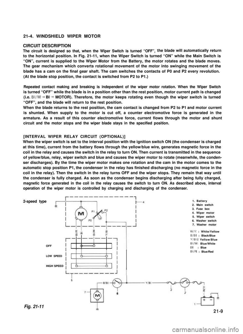
The circuit is designed so that, when the Wiper Switch is turned “OFF”,the blade will automatically return
to the horizontal position. In Fig. 21-11, when the Wiper Switch is turned “ON” while the Main Switch is
“ON”, current is supplied to the Wiper Motor from the Battery, the motor rotates and the blade moves.
The gear mechanism which converts rotational movement of the motor into swinging movement of the
blade has a cam on the final gear shaft. The cam switches the contacts of P0 and P2 every revolution.
(At the blade stop position, the contact is switched from P2 to P1.)
Repeated contact making and breaking is independent of the wiper motor rotation. When the Wiper Switch
is turned “OFF” while the blade is in a position other than the rest position, motor current path is changed
(i.e. BI/W + BI + MOTOR). Therefore, the motor keeps rotating even though the wiper switch is turned
“OFF”, and the blade will return to the rest position.
When the blade returns to the rest position, the cam contact is changed from P2 to P1 and motor current
is shunted. When supply to the motor is cut off, a counter electromotive force is generated in the
armature. As a result of this counter electromotive force, current flows through the motor and shunt
circuit and the motor stops and the wiper blade stays in the specified position.
[INTERVAL WIPER RELAY CIRCUIT (OPTIONAL)]
When the wiper switch is set to the interval position with the ignition switch ON (the condenser is charged
at this time), current from the battery flows through the yellow/blue wire, generates magnetic force in the
coil in the relay and causes the switch in the relay to turn ON. Then current is transmitted in the sequence
of yellow/blue, relay, wiper switch and blue and causes the wiper motor to rotate (meanwhile, the conden-
ser discharges). By the time the wiper motor makes one rotation and the cam in the motor comes to the
automatic stop position P1, the condenser in the relay has finished discharging (no magnetic force in the
coil in the relay). Then the switch in the relay turns OFF and the wiper stops. They remain that way until
the condenser is fully charged. As soon as the condenser begins discharging after being fully charged,
magnetic force generated in the coil in the relay causes the switch to turn ON. As described above, interval
operation of the wiper motor is controlled by charging and discharging of the condenser.
2-speed type
OFF
1. Battery2. Main switch
3. Fuse box4. Wiper motor5. Wiper switch
6. Washer switch7. Washer motor
W/Y : White/Yellow
B/BI : Black/Blue
Y/El: Yellow/Blue
BI/W: Blue/WhiteBI: Blue
LOW SPEED
BIIR : Blue/Red
HIGH SPEED
Fig. 21-11
6
21-9
Page 457 of 962

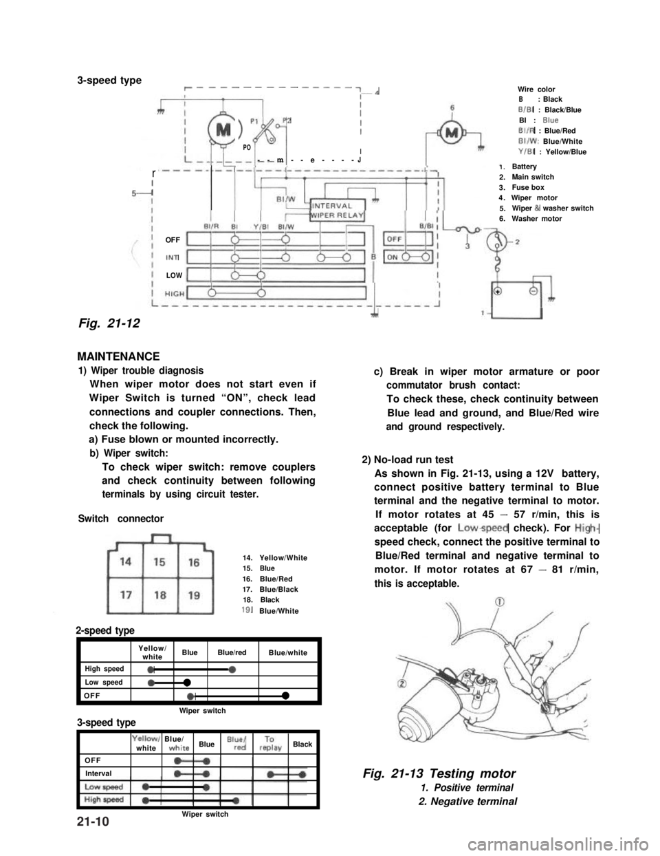
3-speed typer __-- - ---- - ---- ~-*
Fig. 21-12
rI-I
III
MI > p1p2
fil
II0POI--m--e----J
OFF
IN1
LOW
MAINTENANCE
1) Wiper trouble diagnosis
When wiper motor does not start even if
Wiper Switch is turned “ON”, check lead
connections and coupler connections. Then,
check the following.
a) Fuse blown or mounted incorrectly.
b) Wiper switch:
To check wiper switch: remove couplers
and check continuity between following
terminals by using circuit tester.
Switch connector
14.Yellow/White15.Blue16.Blue/Red17.Blue/Black18.Black
18.Blue/White
2-speed type
Yellow/whiteBlueBlue/redBlue/white
High speed0a
Low speed0l
OFFel
Wiper switch
3-speed type
OFF
Interval
Yellowl Blue/whitewhite Blue “lr”,“d/ rzay Black
1.Battery2.Main switch3.Fuse box4.Wiper motor5.Wiper & washer switch6.Washer motor
Wire colorB: BlackB/B1 : Black/BlueBI : BlueBIIR : Blue/RedBI/W: Blue/WhiteY/B1 : Yellow/Blue
2
L
+
A‘U
c) Break in wiper motor armature or poor
commutator brush contact:
To check these, check continuity between
Blue lead and ground, and Blue/Red wire
and ground respectively.
2) No-load run test
As shown in Fig. 21-13, using a 12V battery,
connect positive battery terminal to Blue
terminal and the negative terminal to motor.
If motor rotates at 45 - 57 r/min, this is
acceptable (for Lowspeed check). For High-
speed check, connect the positive terminal to
Blue/Red terminal and negative terminal to
motor. If motor rotates at 67 - 81 r/min,
this is acceptable.
Fig. 21-13 Testing motor
1. Positive terminal
2. Negative terminal
Wiper switch21-10
Page 465 of 962
21-14. FUSE BOX
The fuses in the fuse box is wired as follows.
Head light (R)
Fuse box
Head light (L)Battery7
Horn, Interior light, Door warning
buzzer, ctock (optional)
Stop light
Hazard warning light-W/GI10AW,YI
Cigarette lighter (optional),
Radio (optional)
-w’B++-B7Ignition coil, Fuel cut solenoid,
TWSV, MCSV, vent solenoid,-B/W15A
3
BIBI-
ECM
Heater blower motor-L9
Rear defogger (optional)-Y/G15A
Wiper motor, washer motor-Y/El15A:: BIBI-
Turn signal light, Back-up light-Y10A
Illumination light, License light,
Meter illumination light
-R’y++lFront position and tail light (RI,
Side marker light (RI--RIG5A:: RIB
Lighting switch
Front position and tail light (L), --R,a,
Side marker light (L)
-t
-c
Mainswitch
Tostarter
B/R--,
-
21-18
Page 468 of 962
Fig. 21-39
Instrument Panel Wiring
1.Wire harness No.2
2. Side marker light3.Head light
4.Earth
5.Washer motor
6. To oil pressure gauge
7. To combination light
16
1.Wire harness No. 1
2.To wire~harness No.2
3.To wire harness No.2
4. To fuse box5.Horn relay
6. To combination switch7.To clutch switch
8.Tostop lampswitch15.Doorwarning buzzer
9. To heater blower motor16. Check relay
10.Toradio17.To wipermotor
Il. To heater fan switch18.To illumination lamp
12. To cigar light19. To optional meter
13.Toradio20.Toclock
14.ToECM21.Tometer
Fig. 21-40
21-21
Page 471 of 962
ModelsConvertible/Hardtop ITEM
Tail/Brake light
Side marker light
12V, 3132 cp
12V, 3.8W
License plate light12V,4cp
Back-up light12V32cp
Interior light12v, 5wIMeter pilot light12V,1.4W
Main fuse
Fuse box
POWER TRANSMISSION
Clutch type
Transmission type
Final reduction ratio
0.5 mm2 (fusible link)
1 O/l Of 1 O/l 0/10/1 5/15/l 5/15/l 5/l 0/5/5/5A
Dry, single disc
5-forward all synchromesh, 1 reverse
3.727
Gear ratios
Transfer gear
ratios
Overall reduction ratios:
low3.652
2nd1.947
3rd1.423
4th
1 0.864
reverse1 3.466Ilow range
high range
2.268
1.409
Ilow1 30.8691
Low range
2nd16.457
3rd12.028
4th8.452
t5th7.303I
reverse29.297
low19.177
2nd10.224
3rd7.472
I
-.I4th5.251._..
5th
reverse
4.537
18.201
High range
22-2