Page 103 of 962

Rocker-Arm Shafts
1) Apply engine oil to rocker arms and rocker
arm shafts.
2) install rocker arms, springs and rocker arm
shafts.
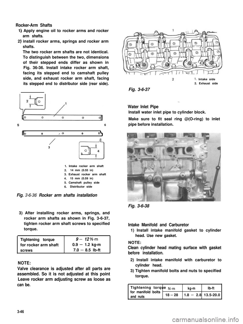
The two rocker arm shafts are not identical.
To distinguish between the two, dimensions
of their stepped ends differ as shown in
Fig. 36-36. Install intake rocker arm shaft,
facing its stepped end to camshaft pulley
side, and exhaust rocker arm shaft, facing
its stepped end to distributor side (rear side).
56
b01000
/3
I
3
I
o-
“7
1. Intake rocker arm shaft
2.14 mm (0.55 in)
3. Exhaust rocker arm shaft
4.15 mm (0.59 in)
5. Camshaft pulley side
6.Distributor side
Fig. 3-6-36 Rocker arm shafts installation
3) After installing rocker arms, springs, and
rocker arm shafts as shown in Fig. 3-6-37,
tighten rocker arm shaft screws to specified
torque.
Tightening torque9 -12 N.m
for rocker arm shaft0.9 -1.2 kg-m
screws7.0 -8.5 lb-ft
NOTE:
Valve clearance is adjusted after all parts are
assembled. So it is not adjusted at this point
Leave rocker arm adjusting screw as loose as
can be.
1. Intake side
2. Exhaust side
Fig. 3-6-37
Water Inlet Pipe
Install water inlet pipe to cylinder block.
Make sure to fit seal ring @(O-ring) to inlet
pipe before installation.
Fig. 3-6-38
Intake Manifold and Carburetor
1) Install intake manifold gasket to cylinder
head. Use new gasket.
NOTE:
Clean cylinder head mating surface with gasket
before installation.
2) Install intake manifold with carburetor to
cylinder head.
3) Tighten manifold bolts and nuts to specified
torque.
Tightening torque ~.mkg-mlb-ftfor manifold bolts
and nuts18 - 281.8 - 2.8 13.5-20.0
3-46
Page 326 of 962

Determination of Shim Thickness for Bevel
Pinion
Thickness of shims to be used on the bevel
pinion varies from one vehicle to another on
account of factors involved in machining and
assembling. Thus, for each vehicle, the thick-
ness of shims necessary for locating pinion in
correct position (for producing a proper backlash
in the mesh between pinion and gear) must be
determined anew at the time of reassembly.
In order to facilitate this determination, a 2-
piece dummy tool (special tool) is made avail-
able. Following procedure is based on use of this
tool and supposes that pinion dummy (one of
the two pieces) is set in carrier, without any
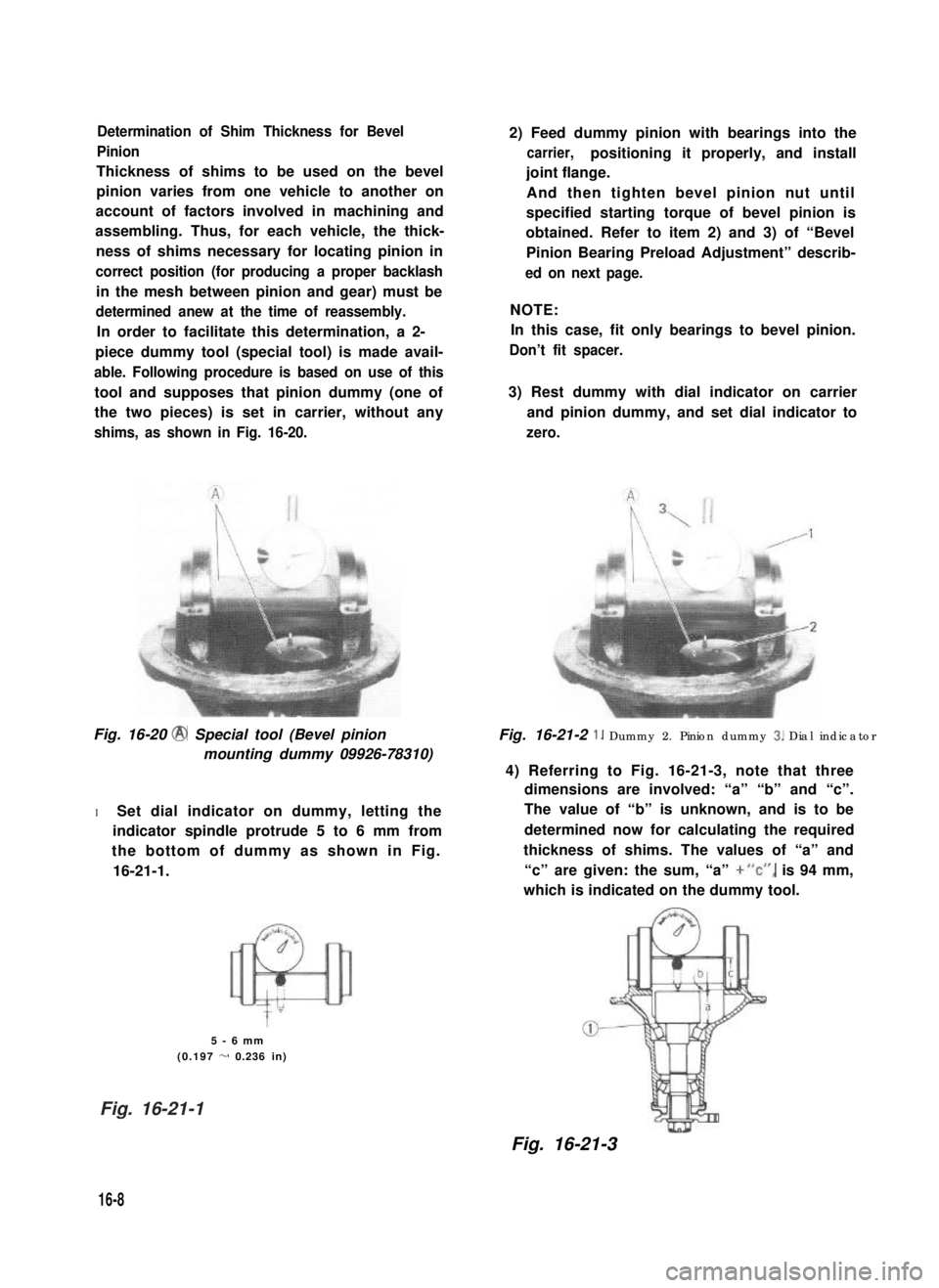
shims, as shown in Fig. 16-20.
Fig. 16-20 @ Special tool (Bevel pinion
mounting dummy 09926-78310)
l Set dial indicator on dummy, letting the
indicator spindle protrude 5 to 6 mm from
the bottom of dummy as shown in Fig.
16-21-1.
5-6mm
(0.197 - 0.236 in)
16-8
2) Feed dummy pinion with bearings into the
carrier,positioning it properly, and install
joint flange.
And then tighten bevel pinion nut until
specified starting torque of bevel pinion is
obtained. Refer to item 2) and 3) of “Bevel
Pinion Bearing Preload Adjustment” describ-
ed on next page.
NOTE:
In this case, fit only bearings to bevel pinion.
Don’t fit spacer.
3) Rest dummy with dial indicator on carrier
and pinion dummy, and set dial indicator to
zero.
Fig. 16-21-2 1. Dummy 2. Pinion dummy 3. Dial indicator
4) Referring to Fig. 16-21-3, note that three
dimensions are involved: “a” “b” and “c”.
The value of “b” is unknown, and is to be
determined now for calculating the required
thickness of shims. The values of “a” and
“c” are given: the sum, “a” +“c”, is 94 mm,
which is indicated on the dummy tool.
Fig. 16-21-3
Fig. 16-21-1
Page 435 of 962
SECTION 20
BODY SERVICE
CONTENTS
20-1. FRONT DOOR...........................................20-2
DESCRIPTION.........................................20-2
REMOVAL............................................2@3
INSTALLATION........................................20-5
WINDSHIELD............................................20- 8
CLEANlNG............................................20- 8
INSTALLATION........................................20-9
20-3. BACK DOOR (APPLICABLE TO HARD TOP VEHICLE).........20-11
CHASSIS DIMENSIONS...................................20-13
20-2.WINDSHIELD
20-4.
20-2
20-2
20-3
20-5
20-8
20-8
20-9
20-11
20-13
20-1
Page 441 of 962
![SUZUKI GRAND VITARA 1987 Service Repair Manual [Door lock inside handle]
Fit the inside handle, adjusting the clearance
between inside open lever @I and outside open
lever @I of the door lock to 0 - 2 mm (0 -
0,079 in) by moving the inside handle SUZUKI GRAND VITARA 1987 Service Repair Manual [Door lock inside handle]
Fit the inside handle, adjusting the clearance
between inside open lever @I and outside open
lever @I of the door lock to 0 - 2 mm (0 -
0,079 in) by moving the inside handle](/manual-img/20/57437/w960_57437-440.png)
[Door lock inside handle]
Fit the inside handle, adjusting the clearance
between inside open lever @I and outside open
lever @I of the door lock to 0 - 2 mm (0 -
0,079 in) by moving the inside handle remote
control rod @ in the arrow direction given in
below figure.
After installation, give it a trial and check if its
play felt then is appropriate.
8. Inside open lever
9. Outside open lever
10. Control rod
11. Door lock striker“B” :0 - 2 mm (0 - 0.079 in.)
Fig. 20-1-21
[Door lock rod pin]
Fix the lock rod with rod pin securely as illust-
rated below.
Rod pin
Fig. 20-1-22
[Door lock striker]
Increase or decrease striker spacers fitted in “A”
position behind the striker to adjust dimensions
to below values as shown in below figure.
After adjustment, check the difference in level
between the door and
there is difference by
striker to right or left.
body and adjust when
moving the door lock
Clearance3.0 mm
(0.12 in.)Spacer fitting position “A”r
Striker
Door lock base\JIA4Yl
y <1 Door inner panelDimension
H 12.7-14.7mm(0.499 - 0.579 in.)
Fig. 20-1-23
Move the striker base up and down so that
striker shaft aligns with the center of the groove
of the door lock (the clearance between the shaft
of door lock striker and lock base is 1.0 mm
(0.04 in.)) in the vertical direction.
CAUTION:
l The striker should be placed vertically.
l Do not adjust the door lock.
Door lock cam
Fig. 20-1-24
20-7