1987 SUZUKI GRAND VITARA fuse
[x] Cancel search: fusePage 40 of 962

2-1. ENGINE
Cond it ion
Poor starting
(Hard starting)
Possible cause
Starter will not run
1. Main fuse blown off
2. Contact not closing in main switch, or this
switch open-circuited
3. Run-down battery
4. Defective magnetic switch of starter
5. Loose battery terminal connection
6. Defective brushes in starter
7. Loose battery cord connection
8. Open in field or armature circuit of starter.
Correction
Replace
Repair or replace
Recharge
Replace
Clean and retighten
Replace
Retighten
Repair or replace
No sparking
1. Defective spark plugAdjust gap, or replace
2. High tension cord short-circuited (grounded)Repair or replace
3. Cracked rotor or cap in distributorReplace
4. Defective signal generator or ignitorReplace
5. Maladjusted signal rotor air gap.Adjust
6. Contact not closing positively in main switch,Replace
or this switch open-circuited
7. Loose or blown fuseSet right or replace
8. Improper ignition timingAdjust
9. Defective ignition coil.Replace
Faulty intake and exhaust systems
1. Carburetor out of adjustment
2. Fuel pump not discharging adequately
3. Clogged fuel filter
4. Defective choke mechanism
5. Loose intake manifold
6. Dirty and clogged carburetor
7. Float level out of adjustment
8. Clogged fuel hose or pipe
9. Not enough fuel in the tank
10. Malfunctioning fuel cut solenoid valve
Adjust
Replace
Clean, or replace
Repair or replace
Retighten
Disassemble and clean
Adjust
Clean or replace
Refill
Check solenoid valve for
proper operation and
replace if necessary
Abnormal engine internal condition
1. Ruptured cylinder head gasket
2. Improper valve clearance
3. Weakened or broken valve spring
4. Loose manifold, permitting air to be
drawn in
5. Worn pistons, rings or cylinders
Replace
Adjust
Replace
Retighten and, as neces-
sary, replace gasket
Replace worn rings and
pistons and rebore as
necessary
2-2
Page 55 of 962
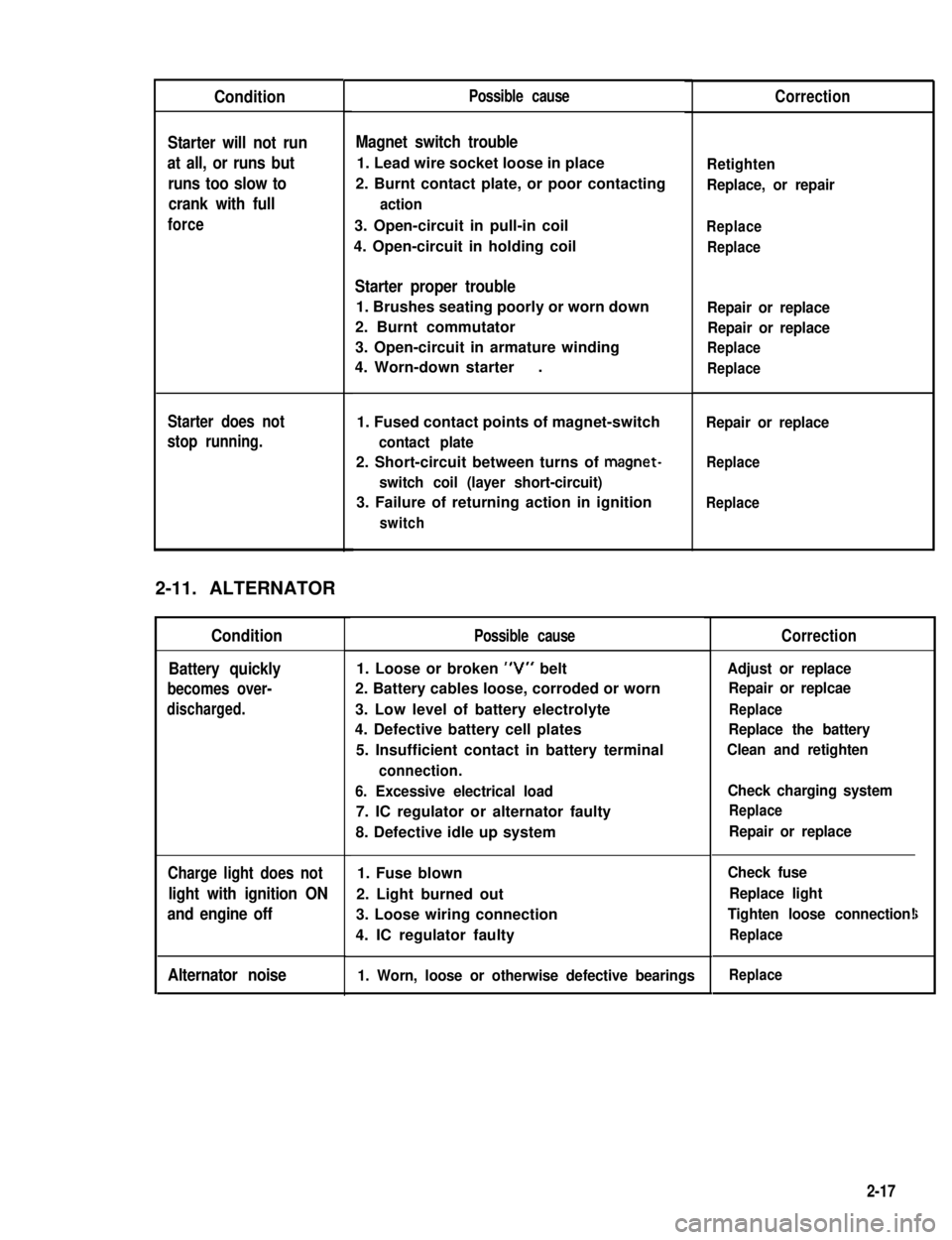
Condition
Starter will not run
at all, or runs but
runs too slow to
crank with full
force
Starter does not
stop running.
2-11. ALTERNATOR
Condition
Battery quickly
becomes over-
discharged.
Charge light does not
light with ignition ON
and engine off
Alternator noise
Possible cause
Magnet switch trouble
1. Lead wire socket loose in place
2. Burnt contact plate, or poor contacting
action
3. Open-circuit in pull-in coil
4. Open-circuit in holding coil
Starter proper trouble
1. Brushes seating poorly or worn down
2. Burnt commutator
3. Open-circuit in armature winding
4. Worn-down starter.
1. Fused contact points of magnet-switch
contact plate
2. Short-circuit between turns of magnet-
switch coil (layer short-circuit)
3. Failure of returning action in ignition
switch
Possible cause
1. Loose or broken “V” belt
2. Battery cables loose, corroded or worn
3. Low level of battery electrolyte
4. Defective battery cell plates
5. Insufficient contact in battery terminal
connection.
6. Excessive electrical load
7. IC regulator or alternator faulty
8. Defective idle up system
1. Fuse blown
2. Light burned out
3. Loose wiring connection
4. IC regulator faulty
1. Worn, loose or otherwise defective bearings
Correction
Retighten
Replace, or repair
Replace
Replace
Repair or replace
Repair or replace
Replace
Replace
Repair or replace
Replace
Replace
Correction
Adjust or replace
Repair or replcae
Replace
Replace the battery
Clean and retighten
Check charging system
Replace
Repair or replace
Check fuse
Replace light
Tighten loose connection!
Replace
i
Replace
2-17
Page 56 of 962

2-12. WIPER MOTOR
Condition
Wiper will not run
Wiper will not stop
running
Wiper stops at
wrong position
Poor wiping action
Possible causeCorrection
1. Fuse set loose or blown offTighten or replace
2. Incomplete metal-to-metal contact in con-
nector.
Repair
3. Worn or floating brushesReplace or repair
4. Dirty or burnt commutatorRepair or replace
5. Short-circuited or fused field coilReplace
6. Loose terminal connection on wiper switchRepair
1. Defective wiper switchRepair or replace
.
1. Improper wiper arm settingRepair
2. Cover plate incorrectly positioned in plcaeRepair
1. Insufficient pressure of wiper armReplace
2. Deteriorated or hardened bladeReplace
3. Blade improperly setRepair or replace
4. Windshield dirty with oilClean
2-13. FUEL METER
Condition
Faulty meter
indication
No indication
Possible cause
1. Incomplete metal-to-metal contact in
terminal connections
2. Defective receiver gauge due to burnt point
or deformed bimetal element
3. Erratic float movement
4. Defective grounding (for float and gauge)
1. Open-circuit
2. Open-circuited heat wire
3. Burnt point
4. Deformed bimetal element
5. Open-circuited resistor
Correction
Retighten
Replace
Repair or replace
Repair
Repair
Replace
Replace
Replace
Replace
2-18
Page 147 of 962
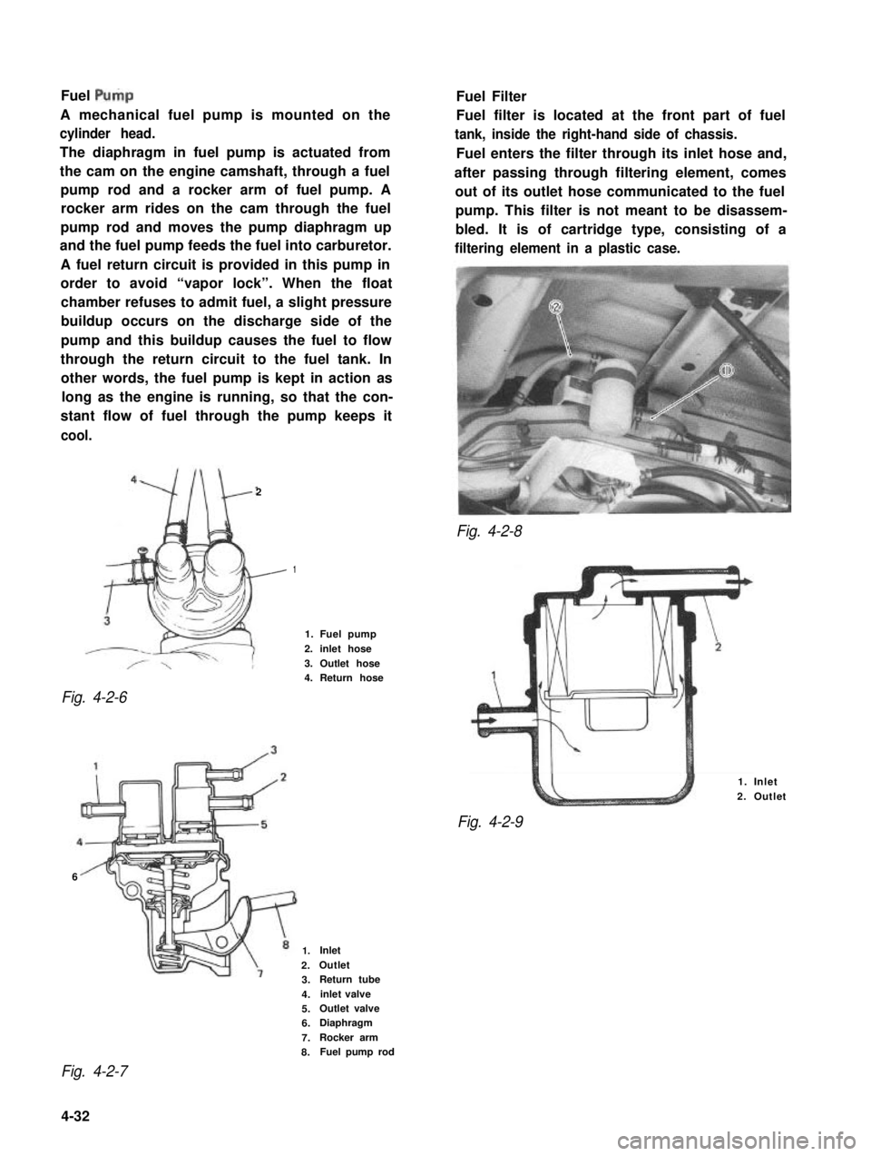
Fuel Pulp
A mechanical fuel pump is mounted on the
cylinder head.
The diaphragm in fuel pump is actuated from
the cam on the engine camshaft, through a fuel
pump rod and a rocker arm of fuel pump. A
rocker arm rides on the cam through the fuel
pump rod and moves the pump diaphragm up
and the fuel pump feeds the fuel into carburetor.
A fuel return circuit is provided in this pump in
order to avoid “vapor lock”. When the float
chamber refuses to admit fuel, a slight pressure
buildup occurs on the discharge side of the
pump and this buildup causes the fuel to flow
through the return circuit to the fuel tank. In
other words, the fuel pump is kept in action as
long as the engine is running, so that the con-
stant flow of fuel through the pump keeps it
cool.
2
Fig. 4-2-8
Fig. 4-2-6
Fuel Filter
Fuel filter is located at the front part of fuel
tank, inside the right-hand side of chassis.
Fuel enters the filter through its inlet hose and,
after passing through filtering element, comes
out of its outlet hose communicated to the fuel
pump. This filter is not meant to be disassem-
bled. It is of cartridge type, consisting of a
filtering element in a plastic case.
1
1. Fuel pump
2. inlet hose
3. Outlet hose4. Return hose
6
1. Inlet
2. Outlet
Fig. 4-2-9
1.Inlet
2.Outlet
3.Return tube
4.inlet valve
5.Outlet valve
6.Diaphragm
7.Rocker arm
8.Fuel pump rod
Fig. 4-2-7
4-32
Page 237 of 962
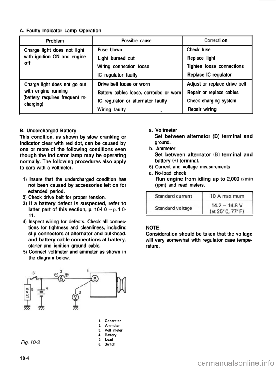
A. Faulty Indicator Lamp Operation
Problem
Charge light does not light
with ignition ON and engine
off
Charge light does not go out
with engine running
(battery requires frequent
re-
charging) Possible cause
Correcti on
Fuse blown
Check fuse
Light burned outReplace light
Wiring connection loose Tighten loose connections
IC regulator faultyReplace IC regulator
Drive belt loose or worn Adjust or replace drive belt
Battery cables loose, corroded or worn Repair or replace cables
IC regulator or alternator faultyCheck charging system
Wiring faulty.Repair wiring
B. Undercharged Battery a. Voltmeter
This condition, as shown by slow cranking or indicator clear with red dot, can be caused by
one or more of the following conditions even
though the indicator lamp may be operating
normally. The following procedures also apply
to cars with a voltmeter.
1) Insure that the undercharged condition has
not been caused by accessories left on for
extended period.
2) Check drive belt for proper tension.
3) If a battery defect is suspected, refer to
latter part of this section, p. 10-l 0 - p, 1 O-
11.
4) Inspect wiring for defects. Check all connec- tions for tightness and cleanliness, including
slip connectors at alternator and bulkhead,
and battery cable connections at battery,
starter and ignition ground cable.
5) Connect voltmeter and ammeter as shown inthe diagram below.
Set between alternator (B) terminal and
ground.
b. Ammeter
Set between alternator (B) terminal and
battery (+) terminal.
6) Current and voltage measurements
a. No-load check
Run engine from idling up to 2,000 r/min
(rpm) and read meters.
NOTE:
Consideration should be taken that the voltage
will vary somewhat with regulator case tempe-
rature.
Fig. 10-3
10-4
1.Generator
2.Ammeter
3. Volt meter
4. Battery
6. Load
6. Switch
Page 448 of 962
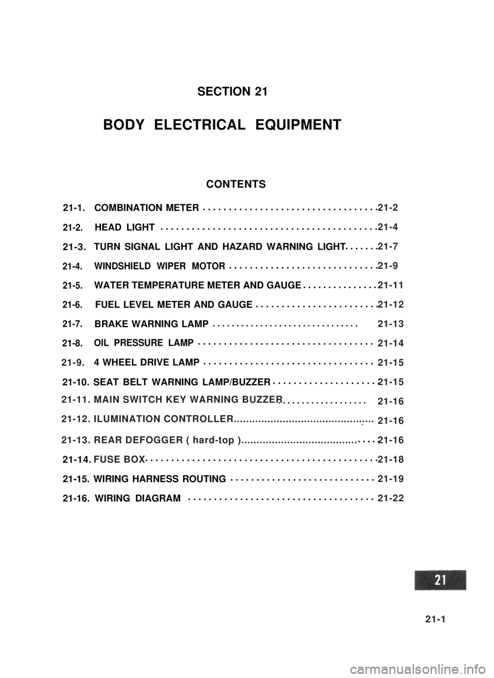
21-1.COMBINATION METER..................................
21-2.HEAD LIGHT..........................................
21-3.TURN SIGNAL LIGHT AND HAZARD WARNING LIGHT.......
21-4.WINDSHIELD WIPER MOTOR.............................
21-5.WATER TEMPERATURE METER AND GAUGE...............
21-6.FUEL LEVEL METER AND GAUGE........................
21-7.BRAKE WARNING LAMP ...............................
21-8.OIL PRESSURE LAMP..................................
4 WHEEL DRIVE LAMP.................................
21-10. SEAT BELT WARNING LAMP/BUZZER.....................
...................
...~I-I
.....
21-14. .............................................
21-15. WIRING HARNESS ROUTING............................
21-16. WIRING DIAGRAM....................................
SECTION 21
BODY ELECTRICAL EQUIPMENT
CONTENTS
21-9.
21-11. MAIN SWITCH KEY WARNING BUZZER
21-12. ILUMINATION CONTROLLER..............................................
21-13. REAR DEFOGGER ( hard-top )......................................
FUSE BOX
21-2
21-4
21-7
21-9
21-11
21-12
21-13
21-14
21-15
21-15
21-16
21-16
21-16
21-18
21-19
21-22
21-1
Page 451 of 962
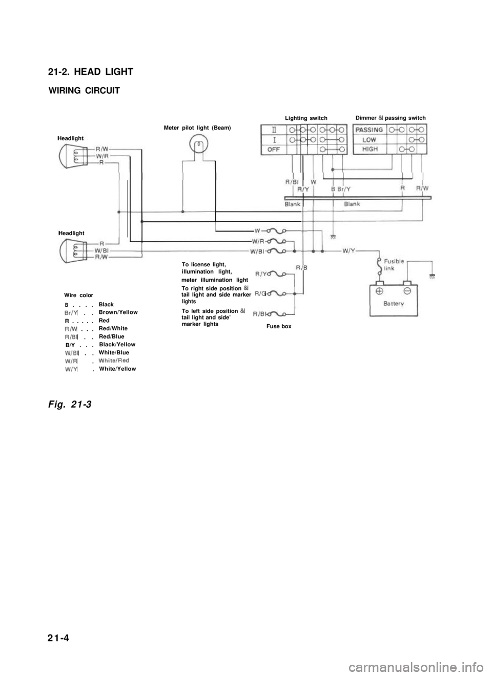
21-2. HEAD LIGHT
WIRING CIRCUIT
Headlight
HeadlightI
Meter pilot light (Beam)II
I
4
Lighting switchDimmer & passing switch
To license light,illumination light,
meter illumination light
Wire color
B. . . .Black
Br/Y . .Brown/Yellow
R.....Red
R/w . . .Red/White
RIBI . .Red/Blue
B/Y . . .Black/Yellow
WIBI . .White/Blue
W/R .WhitelRed
W/Y .White/Yellow
To right side position &tail light and side markerRIGlights
iIB
To left side position 81tail light and side’RIBId
marker lightsFuse box
Fig. 21-3
21-4
Page 454 of 962
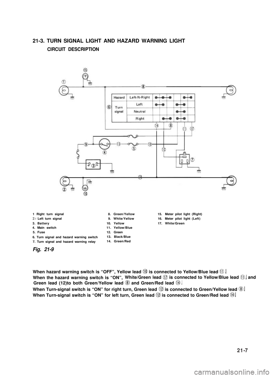
21-3. TURN SIGNAL LIGHT AND HAZARD WARNING LIGHT
CIRCUIT DESCRIPTION
1 Right turn signal
2.. Left turn signal
3. Battery4. Main switch
5. Fuse
6. Turn signal and hazard warning switch
7. Turn signal and hazard warning relay
Fig. 21-9
8.Green/Yellow
9.White/Yellow
10.Yellow11.Yellow/Blue
12.Green
13. Black/Blue
14. Green/Red
15.Meter pilot light(Right)
16.Meter pilot light(Left)
17.White/Green
When hazard warning switch is “OFF”, Yellow lead @ is connected to Yellow/Blue lead 0.
When the hazard warning switch is “ON”,White/Green lead @I is connected to Yellow/Blue lead @I, and
Green lead (12)to both Green/Yellow lead @ and Green/Red lead @.
When Turn-signal switch is “ON” for right turn, Green lead @ is connected to Green/Yellow lead @.
When Turn-signal switch is “ON” for left turn, Green lead @ is connected to Green/Red lead @.
21-7