Page 242 of 962
Brush and Brush holder
Check each brush for wear by measuring its
length as shown. If brush is found worn down to
service limit, replace brush with holder.
Brush lengthStandardService limit
11 mm (0.43 in)5 mm (0.20 in)
Fig. lo-16
Rectifier
Using an ohmmeter, check continuity between
“B” terminal and ground.
Put one tester lead to terminal “B” and the
other lead to ground; then swap two leads. Of
two tester indications, one should be about
10 ohms, meaning continuity, and the other
should be infinity (non continuity).
If not, replace rectifier assembly.
Condenser
Check condenser capacity in regulator.
Fig. 10-18
ICondenser capacity0.5 /JF
ASSEMBLY
Reverse disassembly procedure, using care on
following points.
1) Use a press when forcing bearing into rotor
shaft or drive end frame.
Fig. lo-19
e: Battery terminal
E: Earth
Fig. 10-17
2) Alternator pulley tightening torque.
Tightening torque
50-65N-m15.0-6.5kpm137-47lb-ft
10-9
Page 243 of 962

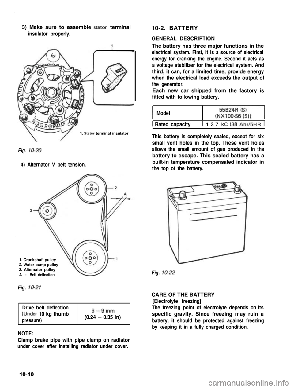
3) Make sure to assemble stator terminal
insulator properly.
10-2. BATTERY
1. Stator terminal insulator
Fig. lo-20
4) Alternator V belt tension.
1. Crankshaft pulley
2. Water pump pulley
3. Alternator pulley
A :Belt deflection
Fig. 1021
Drive belt deflection
(Under 10 kg thumb
pressure)
6-9mm
(0.24 - 0.35 in)
NOTE:
Clamp brake pipe with pipe clamp on radiator
under cover after installing radiator under cover.
GENERAL DESCRIPTION
The battery has three major functions in the
electrical system. First, it is a source of electrical
energy for cranking the engine. Second it acts as
a voltage stabilizer for the electrical system. And
third, it can, for a limited time, provide energy
when the electrical load exceeds the output of
the generator.
Each new car shipped from the factory is
fitted with following battery.
IModel55BzR=l(NXIOO-S6 6))
1 Rated capacityt 137 kC (38 Ah)/5HR j
This battery is completely sealed, except for six
small vent holes in the top. These vent holes
allows the small amount of gas produced in the
battery to escape. This sealed battery has a
built-in temperature compensated indicator in
the top of the battery.
Fig. lo-22
CARE OF THE BATTERY
[Electrolyte freezing]
The freezing point of electrolyte depends on its
specific gravity. Since freezing may ruin a
battery, it should be protected against freezing
by keeping it in a fully charged condition.
10-10
Page 466 of 962
21-15. WIRING HARNESS ROUTING
When reinstalling wire harness, be careful for the following.
l When doing wiring harness related work, make always sure to disconnect battery negative cable from
battery.
l Clamp wire harness securely at prescribed positions.
l Try to route wire harness so as to avoid contact with other parts as much as possible. Use special care
not to let it contact sharp edges of body or other parts.
0 Connect connectors securely.
Engine Room Wiring
1.Wire harness No. 2
2.Battery3. To starter, alternator, head light, small light, horn and etc.
4. To license light, stop/tail light, 4WD switch
5.Earth
6.To wiring harness No.17. To head light, small light, etc.
8.To distributor
9. To ignition coil
10. To back up light switch
11. To fifth switch
12.To TWSV
13.Duty check coupler
14. Thermal engine room switch
15. HAC
16.Ignition coil
17.Brake fluidreservoir
Fig. 27-37
21-19
Page 467 of 962
1.Battery2.Fusible link
3.To starter
4. To starter, alternator, etc
5.Earth6. Earth (To starter mounting bolt)7.Wiring harnessNo.2
64
1
I
1.From wire harnessNo.22. TWSV (Three way solenoid valve)
3. Water temperautre gauge4.Alternator5.Intake manifold
6.Clamp
7.ToVSV6.Thermal switch
9. Mount this terminal horizontal-ly as shown
10.Thermostat cap
1. Wire harness No. 2
2. To distributor
3. To fifth switch4. To back up light switch5. To ignition coil6. Condensor
7. Noise suppressor filter(Clamp it toward engineroom so as to prevent itfrom contacting dashpanel edge.)6. Earth9. To license light, stop/taillight, 4WD switch
10. Ignition coil
11. Distributor12. To wire harness No. 2
13. Ignition coil cap
Fig. 21-38
21-20
Page:
< prev 1-8 9-16 17-24