1987 SUZUKI GRAND VITARA fuel tank removal
[x] Cancel search: fuel tank removalPage 63 of 962

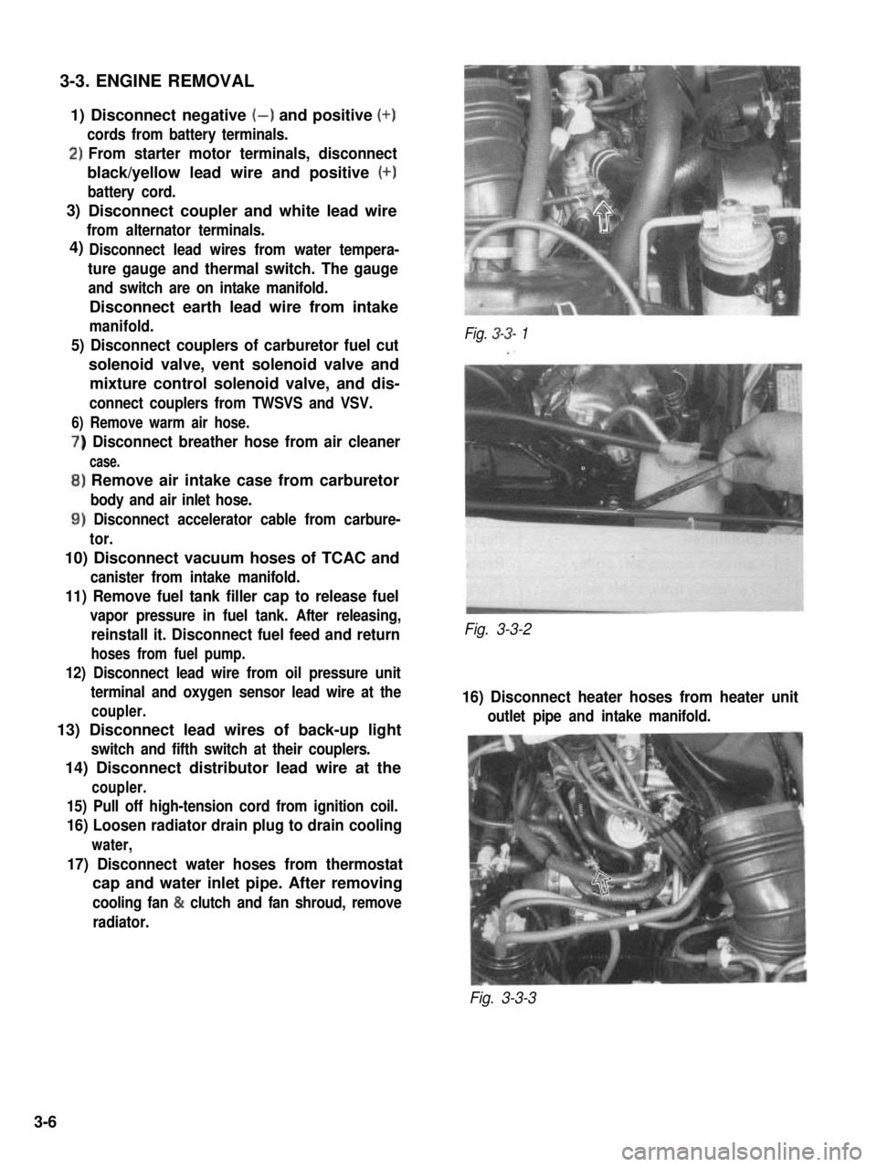
3-3. ENGINE REMOVAL
1) Disconnect negative (-) and positive (+)
cords from battery terminals.
‘)From starter motor terminals, disconnect
black/yellow lead wire and positive (+)
battery cord.
Disconnect coupler and white lead wire
from alternator terminals.
Disconnect lead wires from water tempera-
ture gauge and thermal switch. The gauge
and switch are on intake manifold.
Disconnect earth lead wire from intake
manifold.
5) Disconnect couplers of carburetor fuel cut
solenoid valve, vent solenoid valve and
mixture control solenoid valve, and dis-
connect couplers from TWSVS and VSV.
6) Remove warm air hose.
) Disconnect breather hose from air cleaner
case.
,) Remove air intake case from carburetor
body and air inlet hose.
1) Disconnect accelerator cable from carbure-
tor.
10) Disconnect vacuum hoses of TCAC and
canister from intake manifold.
11) Remove fuel tank filler cap to release fuel
vapor pressure in fuel tank. After releasing,
reinstall it. Disconnect fuel feed and return
hoses from fuel pump.
12) Disconnect lead wire from oil pressure unit
terminal and oxygen sensor lead wire at the
coupler.
13) Disconnect lead wires of back-up light
switch and fifth switch at their couplers.
14) Disconnect distributor lead wire at the
coupler.
15) Pull off high-tension cord from ignition coil.
16) Loosen radiator drain plug to drain cooling
water,
17) Disconnect water hoses from thermostat
cap and water inlet pipe. After removing
cooling fan & clutch and fan shroud, remove
radiator.
Fig. 3-3- 1
Fig. 3-3-2
16) Disconnect heater hoses from heater unit
outlet pipe and intake manifold.
Fig. 3-3-3
3)
4)
3-6
Page 127 of 962

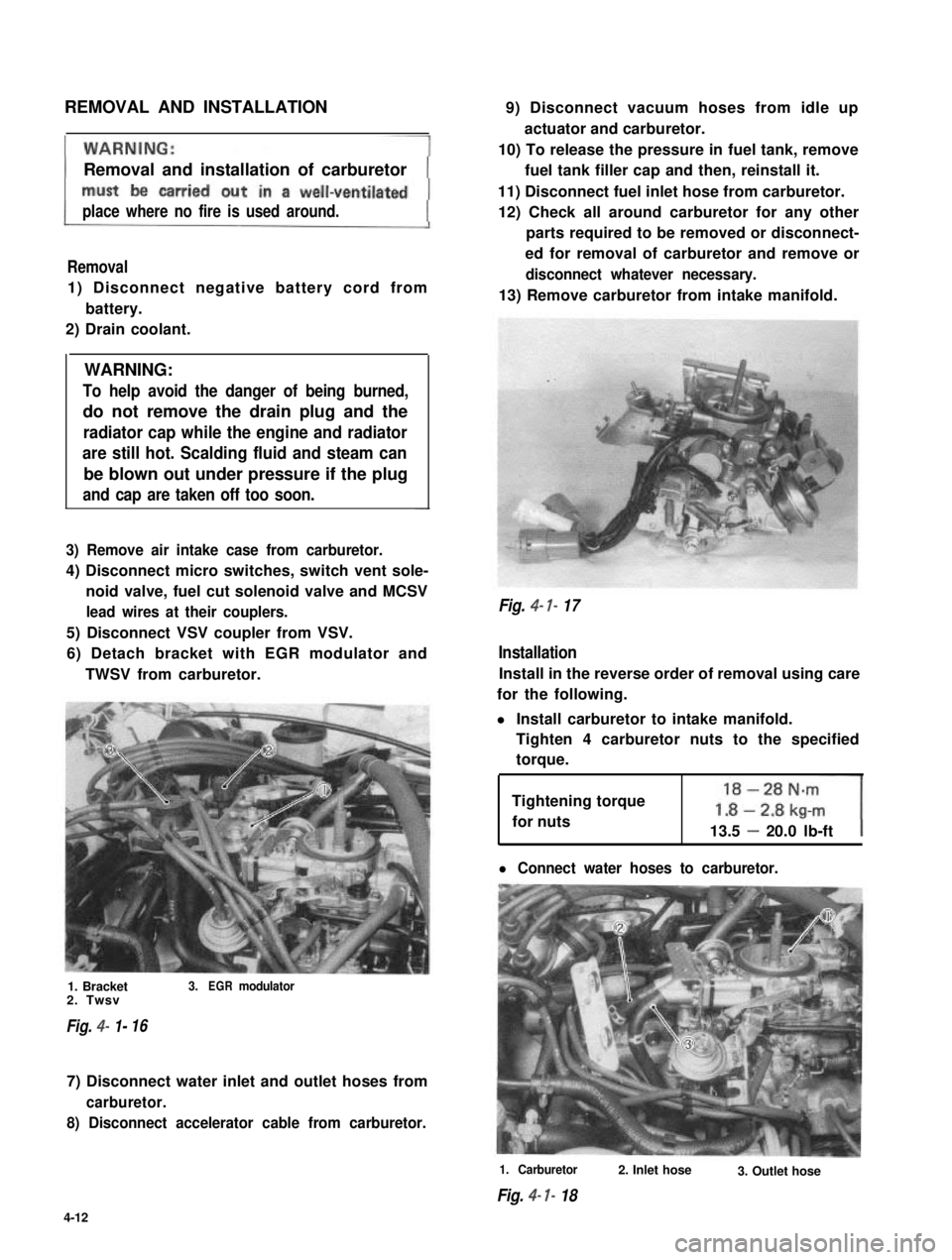
REMOVAL AND INSTALLATION
Removal and installation of carburetor
place where no fire is used around.
Removal
1) Disconnect negative battery cord from
battery.
2) Drain coolant.
WARNING:
To help avoid the danger of being burned,
do not remove the drain plug and the
radiator cap while the engine and radiator
are still hot. Scalding fluid and steam can
be blown out under pressure if the plug
and cap are taken off too soon.
3) Remove air intake case from carburetor.
4) Disconnect micro switches, switch vent sole-
noid valve, fuel cut solenoid valve and MCSV
lead wires at their couplers.
5) Disconnect VSV coupler from VSV.
6) Detach bracket with EGR modulator and
TWSV from carburetor.
1. Bracket3.EGRmodulator2. Twsv
Fig. 4- 1-16
7) Disconnect water inlet and outlet hoses from
carburetor.
8) Disconnect accelerator cable from carburetor.
9) Disconnect vacuum hoses from idle up
actuator and carburetor.
10) To release the pressure in fuel tank, remove
fuel tank filler cap and then, reinstall it.
11) Disconnect fuel inlet hose from carburetor.
12) Check all around carburetor for any other
parts required to be removed or disconnect-
ed for removal of carburetor and remove or
disconnect whatever necessary.
13) Remove carburetor from intake manifold.
Fig. 4- 7- 17
Installation
Install in the reverse order of removal using care
for the following.
l Install carburetor to intake manifold.
Tighten 4 carburetor nuts to the specified
torque.
Tightening torque
for nuts13.5 - 20.0 lb-ft
l Connect water hoses to carburetor.
1. Carburetor
Fig. 4- I- 18
2. Inlet hose3. Outlet hose
4-12
Page 148 of 962

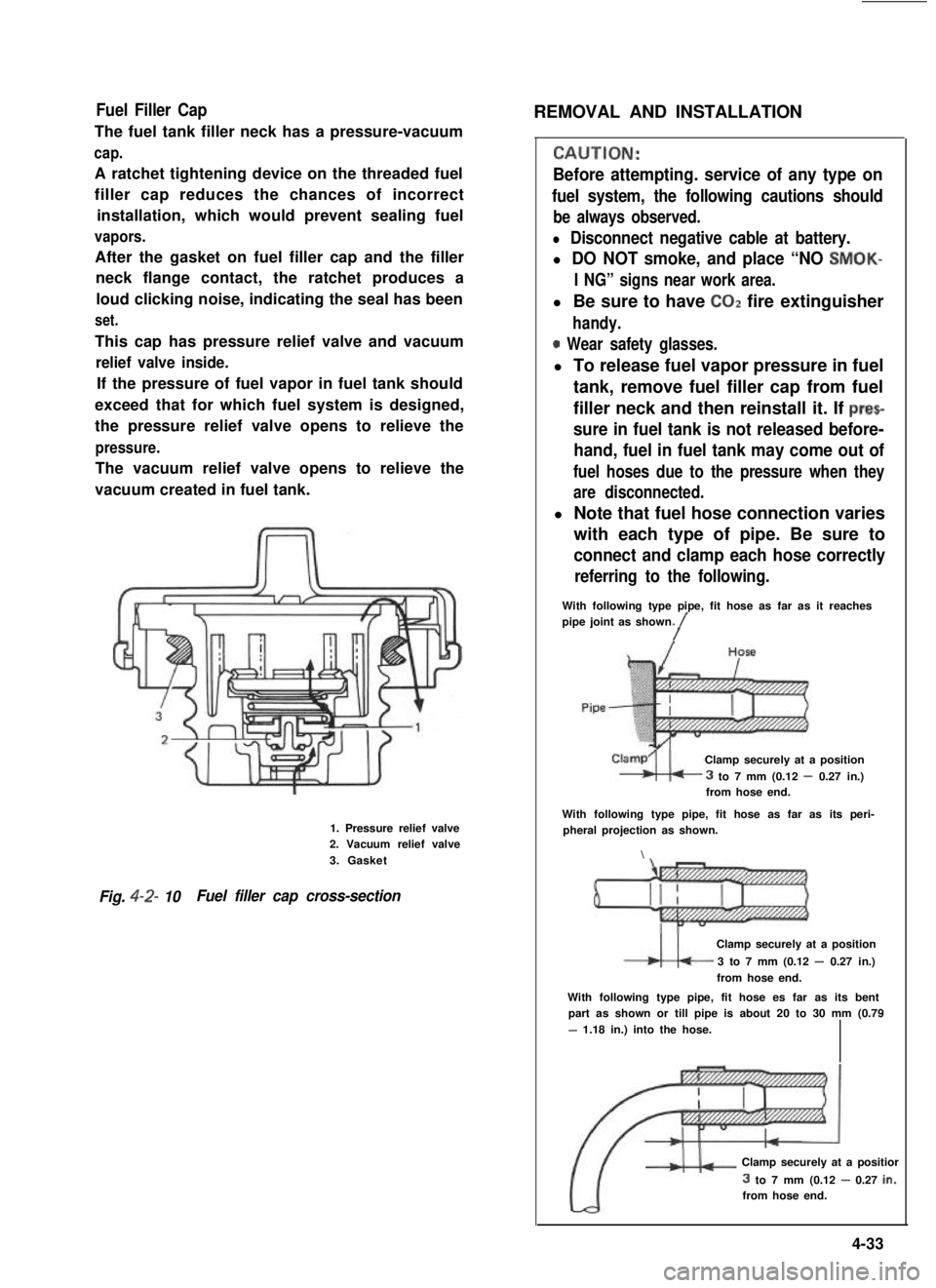
Fuel Filler Cap
The fuel tank filler neck has a pressure-vacuum
cap.
A ratchet tightening device on the threaded fuel
filler cap reduces the chances of incorrect
installation, which would prevent sealing fuel
vapors.
After the gasket on fuel filler cap and the filler
neck flange contact, the ratchet produces a
loud clicking noise, indicating the seal has been
set.
This cap has pressure relief valve and vacuum
relief valve inside.
If the pressure of fuel vapor in fuel tank should
exceed that for which fuel system is designed,
the pressure relief valve opens to relieve the
pressure.
The vacuum relief valve opens to relieve the
vacuum created in fuel tank.
1. Pressure relief valve2. Vacuum relief valve
3. Gasket
Fig. 4-2- 10Fuel filler cap cross-section
REMOVAL AND INSTALLATION
CALJTION:
Before attempting. service of any type on
fuel system, the following cautions should
be always observed.
l Disconnect negative cable at battery.
l DO NOT smoke, and place “NO SMOK-
I NG” signs near work area.
l Be sure to have COZ fire extinguisher
handy.
0 Wear safety glasses.
l To release fuel vapor pressure in fuel
tank, remove fuel filler cap from fuel
filler neck and then reinstall it. If prec
sure in fuel tank is not released before-
hand, fuel in fuel tank may come out of
fuel hoses due to the pressure when they
are disconnected.
l Note that fuel hose connection varies
with each type of pipe. Be sure to
connect and clamp each hose correctly
referring to the following.
With following type pipe, fit hose as far as it reachespipe joint as shown./
Clamp securely at a position
3 to 7 mm (0.12 - 0.27 in.)from hose end.
With following type pipe, fit hose as far as its peri-pheral projection as shown.
\
Clamp securely at a position
3 to 7 mm (0.12 - 0.27 in.)
from hose end.
With following type pipe, fit hose es far as its bentpart as shown or till pipe is about 20 to 30 mm (0.79
- 1.18 in.) into the hose.
Clamp securely at a positior
3 to 7 mm (0.12 - 0.27 in.:from hose end.
4-33
Page 149 of 962
![SUZUKI GRAND VITARA 1987 Service Repair Manual ,Fuel Pump
[ Rem’oval]
1) Disconnect negative cable from battery.
2) Remove fuel filler cap from fuel filler neck to
release fuel vapor pressure in fuel tank. After
releasing, reinstall the cap.
3) SUZUKI GRAND VITARA 1987 Service Repair Manual ,Fuel Pump
[ Rem’oval]
1) Disconnect negative cable from battery.
2) Remove fuel filler cap from fuel filler neck to
release fuel vapor pressure in fuel tank. After
releasing, reinstall the cap.
3)](/manual-img/20/57437/w960_57437-148.png)
,Fuel Pump
[ Rem’oval]
1) Disconnect negative cable from battery.
2) Remove fuel filler cap from fuel filler neck to
release fuel vapor pressure in fuel tank. After
releasing, reinstall the cap.
3) Disconnect fuel inlet, outlet and return hoses
from fuel pump.
Fuel Filter
[Removal]
1) Disconnect negative cable from battery.
2) Remove fuel filler cap to release fuel vapor
pressure in fuel tank. After releasing, reinstall
the cap.
3) Disconnect inlet and outlet hoses from fuel
filter.
4) Remove fuel filter with clamp.
[Installation]
1) Install filter and clamp, and connect inlet
and outlet hoses to fuel filter.
NOTE:.
The top connection is for outlet hose, the
lower one for inlet hose.
1. Fuel pump
2. Inlet hose3. Outlet hose
4. Return hose
Fig. 4-2-l 1
4) Remove fuel pump from cylinder head.
5) Remove fuel pump rod from cylinder head.
2
1. Fuel pump rod
2. Cylinder head
[Installation]
Reverse removal procedure for installation
using care for the following.
l After oiling it,install fuel pump rod to
cylinder head.
0 Use new fuel pump gasket.
l Make sure for proper hose connection.
0 Upon completion of installation, start engine
and check fuel hose or its joints for leaks.
1.Fuel filter3.From fueltank
2.To fuel pump4.Clamp
Fig.4-2-13
2) Connect negative cable to battery.
3) After installation, start engine and check it
for leaks.
Fuel Tank
[Removal]
1) Disconnect negative cable from battery.
2) Disconnect fuel level gauge lead wire.
3) To release the pressure in fuel tank, remove
fuel filler cap and then, reinstall it.
4) Raise car on hoist.
5) Drain fuel by removing drain plug.
6) Remove filler hose protector.
7) Disconnect filler hose from fuel tank.
.8) Disconnect fuel hosesand pipe from fuel tank.
9) Remove fuel tank.
4-34
Page 150 of 962
![SUZUKI GRAND VITARA 1987 Service Repair Manual [Fuel tank purging procedure]
WARNING:
This purging procedure will NOT remove
all fuel vapor. Do not attempt any repair
on tank where heat or flame is required, as
an explosion resulting in personal i SUZUKI GRAND VITARA 1987 Service Repair Manual [Fuel tank purging procedure]
WARNING:
This purging procedure will NOT remove
all fuel vapor. Do not attempt any repair
on tank where heat or flame is required, as
an explosion resulting in personal i](/manual-img/20/57437/w960_57437-149.png)
[Fuel tank purging procedure]
WARNING:
This purging procedure will NOT remove
all fuel vapor. Do not attempt any repair
on tank where heat or flame is required, as
an explosion resulting in personal injury
cou Id occur.J
The following procedure is used for purging the
fuel tank.
1) After removing fuel tank, remove all hoses,
fuel level gauge from fuel tank.
2) Drain all remaining fuel from tank.
3) Move tank to flushing area.
4) Fill tank with warm water or tap water, and
agitate vigorously and drain. Repeat this
washing until inside of tank is clean.
Replace tank if inside is rusty.
5) Completely flush out remaining water after
washing.
[ Installation]
Reverse removal procedure for installation using
care for the following.
Tightening torque30-45 Nm
for fuel tank(3.0- 4.5 kg-m)
drain plug(22.0 - 32.5 lb-ft)
Refer to Fig. 4-2-5 for piping and clamp posi-
tions.
l Make sure for correct hose-to-pipe connec-
tion.
l Clamp hoses securely.
l Upon completion of installation, start engine
and check hose joints for leaks.
MAINTENANCE SERVICES
Fuel Lines
Visually inspect fuel lines and connections for
evidence of fuel leakage, hose cracking, and
damage. Make sure all clamps are secure.
Repair leaky joints, if any.
Replace hoses that are suspected of being crack-
ed.
Fig. 4-2-14
Fuel Filler (tank) Cap
Visually inspect gasket of fuel filler cap.
If it is damaged or deteriorated, replace filler cap
with new one.
NOTE:
If cap requires replacement, only a cap with
the same features should be used. Failure to
use correct cap can result in a serious malfunc-
tion of the system.
Fig. 4-2-15
1. Fuel filler cap
2. Fuel filler capgasket
Fuel Filter
As said before, this filter does not permit dis-
assembly: it is to be replaced with a new one
periodically.
Replace fuel filter referring to previous item of
“Fuel Filter Removal and Installation”.
This servicing must be performed in a well
ventilated area and away from any open
flames (such as gas hot water heaters).
4-35