Page 75 of 962

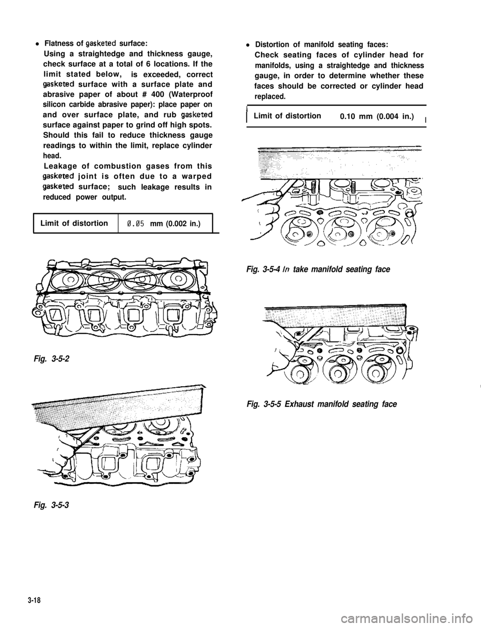
l Flatness of gasketed surface:
Using a straightedge and thickness gauge,
check surface at a total of 6 locations. If the
limit stated below,is exceeded, correct
gasketed surface with a surface plate and
abrasive paper of about # 400 (Waterproof
silicon carbide abrasive paper): place paper on
and over surface plate, and rub gasketed
surface against paper to grind off high spots.
Should this fail to reduce thickness gauge
readings to within the limit, replace cylinder
head.
Leakage of combustion gases from this
gasketed joint is often due to a warped
gasketed surface;such leakage results in
reduced power output.
l Distortion of manifold seating faces:
Check seating faces of cylinder head for
manifolds, using a straightedge and thickness
gauge, in order to determine whether these
faces should be corrected or cylinder head
replaced.
ILimit of distortion0.10 mm (0.004 in.)I
Limit of distortion0.05 mm (0.002 in.)
Fig. 3-5-4 In take manifold seating face
Fig. 3-5-2
Fig. 3-5-5 Exhaust manifold seating face
Fig. 3-5-3
3-18
Page 436 of 962
20-1. FRONT DOOR
DESCRIPTION
1. Door open stopper band garnish
2. Door open stopper band
3.Trim protector
4. Front door panel5. Door trim clip6. Door lower hinge
7. Door upper hinge
8.Door weatherstrip9. Door trim board
10.Door glass11. Glass bottom channel
12.Regulator
13. Regulator roller holder
14.Inside handle
15. Door key cylinder
16.Outside handle
17. Door lock ass’y
18. Door lock striker
19.Striker spacer20.Regulator handle 21. Inside handle case
22. Inside pull handle23. Water proof film
Fig. 20-1-1
20-2
Page 437 of 962
REMOVAL
Door Window Glass
1) Remove door window regulator handle.
Fig. 20-1-2
2) Remove inside handle case.
Fig. 20-1-3
3) Remove inside pull handle.
4) Loosen two screws securing the stopper
band, and take off the band.
5) Remove door trim board.
Fig. 20-1-5
6) Remove the door water proof film.
Fig. 20-1-6
7) Remove the glass inside and outside scrape.
Fig. 20-1-4 Fig. 20-1-7
20-3
Page 440 of 962

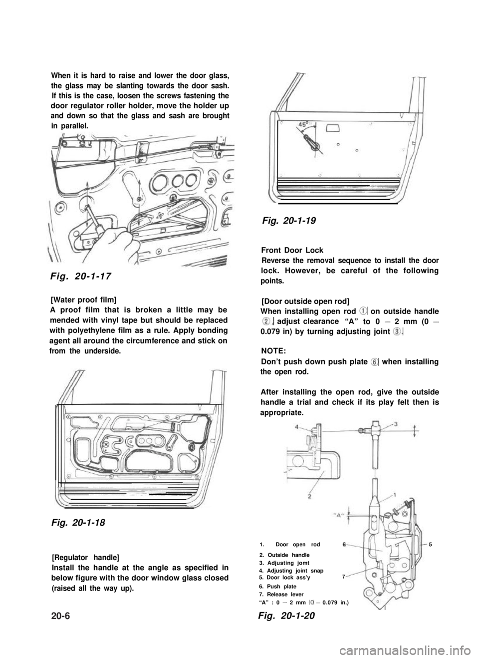
When it is hard to raise and lower the door glass,
the glass may be slanting towards the door sash.
If this is the case, loosen the screws fastening the
door regulator roller holder, move the holder up
and down so that the glass and sash are brought
in parallel.
Fig. 20-1-17
[Water proof film]
A proof film that is broken a little may be
mended with vinyl tape but should be replaced
with polyethylene film as a rule. Apply bonding
agent all around the circumference and stick on
from the underside.
Fig. 20-1-18
[Regulator handle]
Install the handle at the angle as specified in
below figure with the door window glass closed
(raised all the way up).
Fig. 20-1-19
Front Door Lock
Reverse the removal sequence to install the door
lock. However, be careful of the following
points.
[Door outside open rod]
When installing open rod @ on outside handle
0, adjust clearance“A” to 0 - 2 mm (0 -
0.079 in) by turning adjusting joint 0.
NOTE:
Don’t push down push plate @ when installing
the open rod.
After installing the open rod, give the outside
handle a trial and check if its play felt then is
appropriate.
1. Door rodopen65
2. Outside handle
3. Adjusting jomt4. Adjusting joint snap5. Door lock ass’y7
6. Push plate
7. Release lever
“A” : 0 - 2 mm (0-0.079in.)
Fig. 20-1-20
v
20-6