1987 SUZUKI GRAND VITARA lock
[x] Cancel search: lockPage 109 of 962
Clutch Disc and Cover?
Install clutch disc and cover.
For installation, refer to p. 11-7 of SECTION 11
CLUTCH in this manual and torque each bolt to
specification.
Transmission Assembly
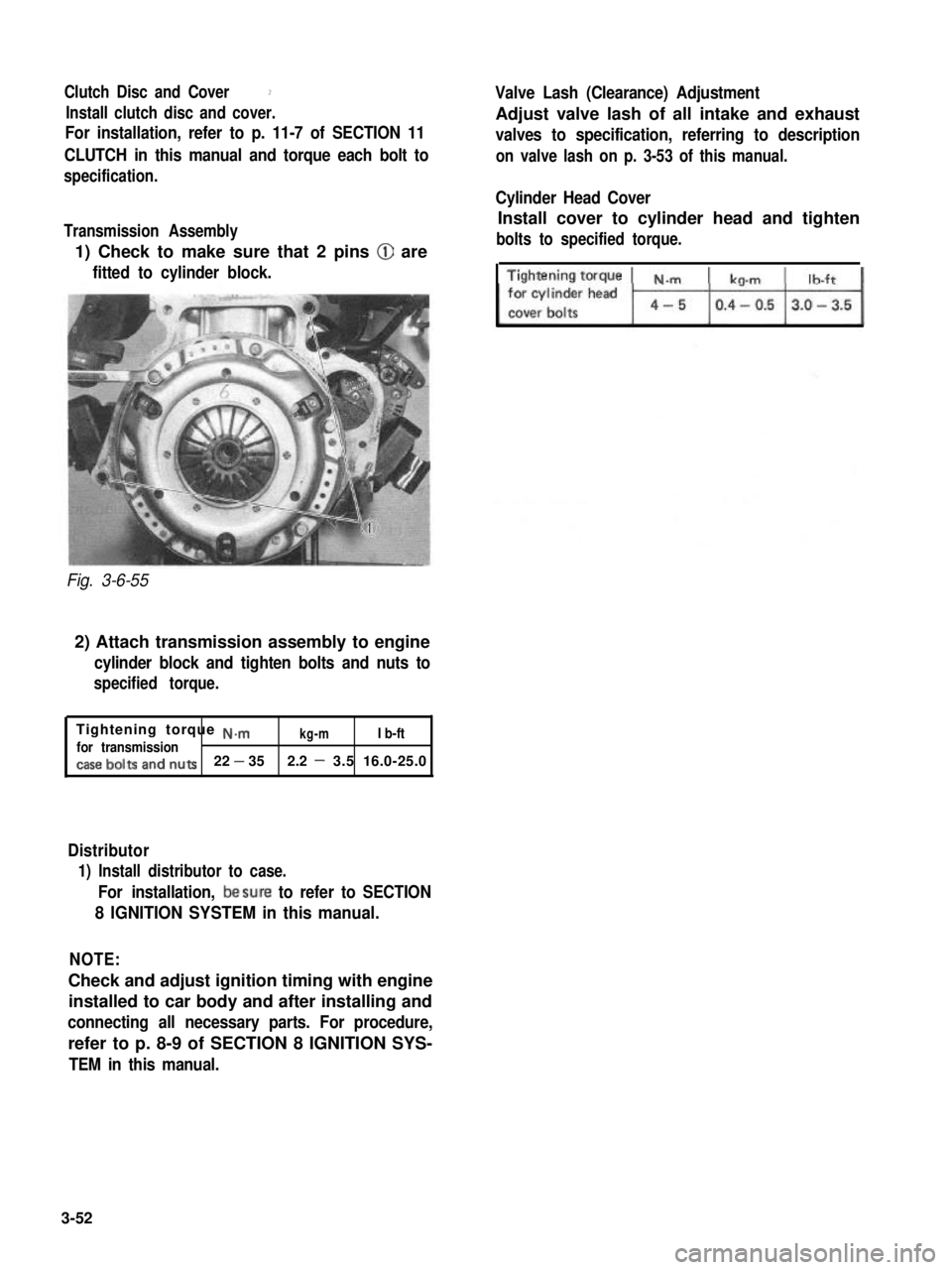
1) Check to make sure that 2 pins @ are
fitted to cylinder block.
Fig. 3-6-55
2) Attach transmission assembly to engine
cylinder block and tighten bolts and nuts to
specified torque.
Tightening torque ~.mkg-mI b-ftfor transmission,.aSe bolts an,-j nutS22 - 352.2 - 3.5 16.0-25.0
Distributor
1) Install distributor to case.
For installation, besure to refer to SECTION
8 IGNITION SYSTEM in this manual.
Valve Lash (Clearance) Adjustment
Adjust valve lash of all intake and exhaust
valves to specification, referring to description
on valve lash on p. 3-53 of this manual.
Cylinder Head Cover
Install cover to cylinder head and tighten
bolts to specified torque.
NOTE:
Check and adjust ignition timing with engine
installed to car body and after installing and
connecting all necessary parts. For procedure,
refer to p. 8-9 of SECTION 8 IGNITION SYS-
TEM in this manual.
3-52
Page 110 of 962
3-7. ENGINE INSTALLATION
1) Lower engine with transmission into vehicle,
but do not remove lifting device.
2) Tighten engine mounting bracket bolts
(right and left) and transmission mounting
bolts to specification. Refer to p. 3-58.
3) Remove lifting device.
4) Reverse removal procedures for installation
of remainder.
5) Adjust accelerator cable play and clutch
cable play.
6) Connect vacuum hoses securely. Refer to
section 5 “EMISSION CONTROL SYSTEM”
for correct connection.
7) Connect wire harnesses and couplers secure-
IY.
8) Tighten bolts and nuts to specified torque.
For individual specification, refer to each
section.
9) Fill specified amount of specified trans-
mission oil and engine oil. For the detail,
refer to SECTION 1 PERIODIC MAINTE-
NANCE SERVICE of this manual.
10) After adjusting water pump belt tension to
specification, fill specified amount of engine
cooling water.
11) Before starting engine, check again to ensure
that all parts once disassembled or discon-
nected are back in place securely.
12)Start engine and check ignition timing. If
it is not to specified timing, adjust it, referr-
ing to SECTION 8 of this manual.
13) After engine is started, check for oil leak,
abnormal noise and other malcondition.
Also, check each part for operation.
3-8. ENGINE MAINTENANCE SERVICE
Fan Belt
Adjust belt tension as outlined in SECTION 6
ENGINE COOLING SYSTEM (p. 6-10).
Ignition Timing
Refer to IGNITION TIMING, Page 8-9.
Carburetor
fidjustments to be made are detailed in SEC-
TION 4 (p. 4-19).
Valve Lash (Clearance)
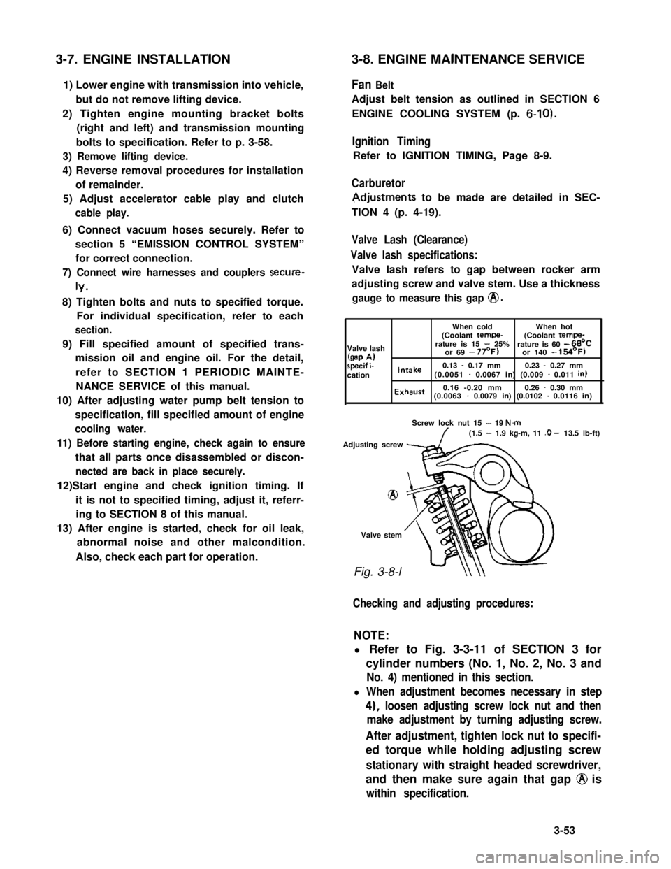
Valve lash specifications:
Valve lash refers to gap between rocker arm
adjusting screw and valve stem. Use a thickness
gauge to measure this gap @.
When coldWhen hot(Coolant tempe-(Coolant tempa-
Valve lashrature is 15 - 25%rature is 60 - 66’C
(gap A)or 69 - 77’F)or 140 - 154’F)
specif i-0.13 - 0.17 mm0.23 - 0.27 mmcationIntake(0.0051 - 0.0067 in) (0.009 - 0.011 in)
Exhaust0.16 -0.20 mm0.26 - 0.30 mm(0.0063 - 0.0079 in) (0.0102 - 0.0116 in)
Screw lock nut 15 - 19 N.m(1.5 - 1.9 kg-m, 11 .O - 13.5 lb-ft)
Adjusting screw
8
Valve stem
Fig. 3-8-l
Checking and adjusting procedures:
NOTE:
l Refer to Fig. 3-3-11 of SECTION 3 for
cylinder numbers (No. 1, No. 2, No. 3 and
No. 4) mentioned in this section.
l When adjustment becomes necessary in step
4), loosen adjusting screw lock nut and then
make adjustment by turning adjusting screw.
After adjustment, tighten lock nut to specifi-
ed torque while holding adjusting screw
stationary with straight headed screwdriver,
and then make sure again that gap @ is
within specification.
3-53
Page 111 of 962
1) Remove cylinder head cover.
2) Remove ignitiontiming check window
rubber plug from clutch housing of trans-
mission case.
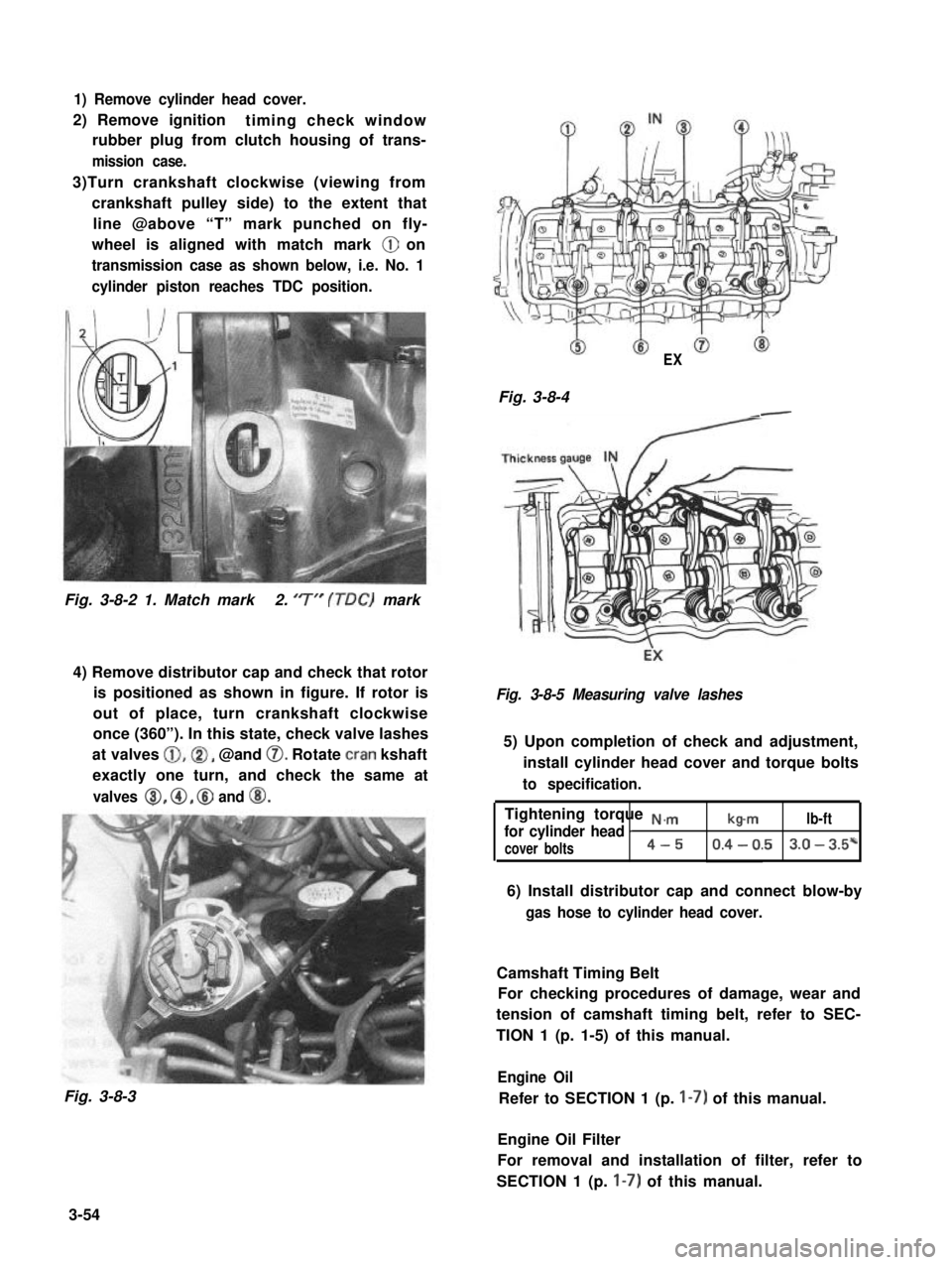
3)Turn crankshaft clockwise (viewing from
crankshaft pulley side) to the extent that
line @above “T” mark punched on fly-
wheel is aligned with match mark @ on
transmission case as shown below, i.e. No. 1
cylinder piston reaches TDC position.
Fig. 3-8-2 1. Match mark2. ‘7” (TDC) mark
4) Remove distributor cap and check that rotor
is positioned as shown in figure. If rotor is
out of place, turn crankshaft clockwise
once (360”). In this state, check valve lashes
at valves @,@I, @and 0. Rotate cran kshaft
exactly one turn, and check the same at
valves 8, @, @ and @I.
Fig. 3-8-3
EX
Fig. 3-8-4-
Fig. 3-8-5 Measuring valve lashes
5) Upon completion of check and adjustment,
install cylinder head cover and torque bolts
to specification.
Tightening torque N.,.,.,
for cylinder head Ib-mlb-ft
cover bolts4-50.4 - 0.53.0 - 3.5*
6) Install distributor cap and connect blow-by
gas hose to cylinder head cover.
Camshaft Timing Belt
For checking procedures of damage, wear and
tension of camshaft timing belt, refer to SEC-
TION 1 (p. 1-5) of this manual.
Engine Oil
Refer to SECTION 1 (p. I-7) of this manual.
Engine Oil Filter
For removal and installation of filter, refer to
SECTION 1 (p. I-7) of this manual.
3-54
Page 113 of 962
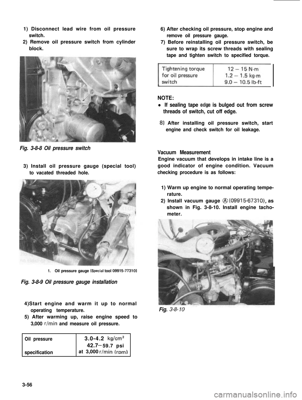
1) Disconnect lead wire from oil pressure
switch.
2) Remove oil pressure switch from cylinder
block.
6) After checking oil pressure, stop engine and
remove oil pressure gauge.
7) Before reinstalling oil pressure switch, be
sure to wrap its screw threads with sealing
tape and tighten switch to specified torque.
NOTE:
l If sealing tape edge is bulged out from screw
threads of switch, cut off edge.
8) After installing oil pressure switch, start
engine and check switch for oil leakage.
Fig. 3-8-8 Oil pressure switch
3) Install oil pressure gauge (special tool)
to vacated threaded hole.
Vacuum Measurement
Engine vacuum that develops in intake line is a
good indicator of engine condition. Vacuum
checking procedure is as follows:
1.Oil pressure gauge k+ecial tool O!Xil5-77310)
Fig. 3-8-9 Oil pressure gauge installation
4)Start engine and warm it up to normal
operating temperature.
5) After warming up, raise engine speed to
3,000 r/min and measure oil pressure.
Oil pressure
specification
3.0-4.2 kg/cm2
42.7 59.7 psi-
at 3,000
1) Warm up engine to normal operating tempe-
rature.
2) Install vacuum gauge @ (09915-67310), as
shown in Fig. 3-8-10. Install engine tacho-
meter.
Fig. 3-8- 10
3-56
Page 115 of 962
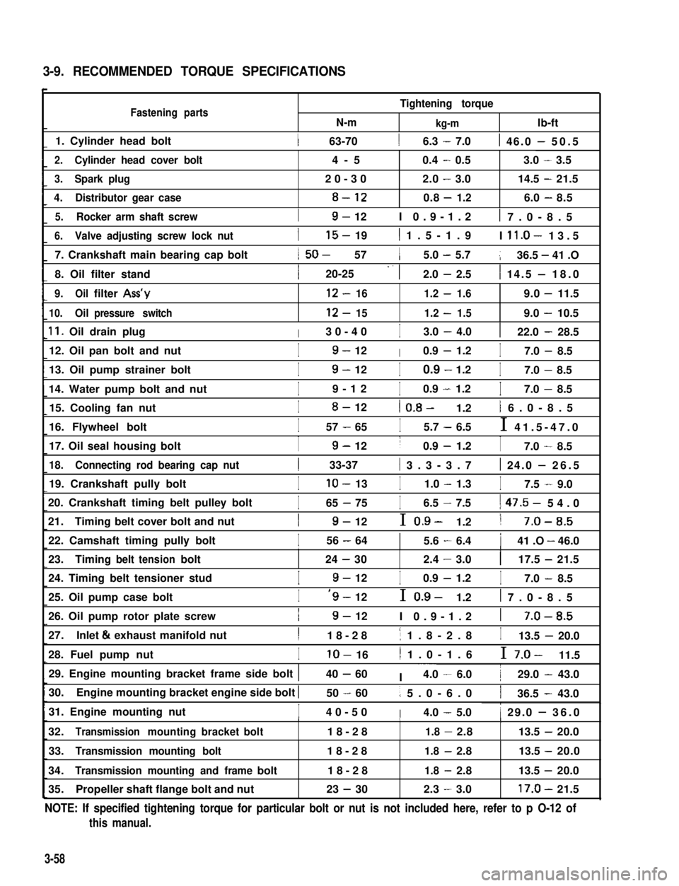
3-9. RECOMMENDED TORQUE SPECIFICATIONS
Fastening partsN-m
Tightening torque
kg-mlb-ft
1. Cylinder head bolt1 63-7016.3 - 7.01 46.0 - 50.5
2.Cylinder head cover bolt4-50.4-0.53.0-3.5
3.Spark plug20-302.0-3.014.5-21.5
4.Distributor gear case8-120.8-1.26.0-8.5
5.Rocker arm shaft screwI9- 12I 0.9-1.21 7.0-8.5
6.Valve adjusting screw lock nut
7. Crankshaft main bearing cap bolt
8. Oil filter stand
I15- 191 1.5-1.9I ll.O- 13.5
1 50- 5715.0 - 5.7136.5 - 41 .O
I20-25 -. 12.0 - 2.51 14.5 - 18.0
9.Oilfilter Ass’y12-161.2-1.69.0-11.5
10.Oilpressure switch12-151.2-1.59.0-10.5
11. Oil drain plugI30-40I3.0 - 4.0122.0 - 28.5
12. Oil pan bolt and nutI9- 12I0.9 - 1.2I7.0 - 8.5
13. Oil pump strainer bolt
14. Water pump bolt and nut
I9- 12I0.9 - 1.2I7.0 - 8.5
I9-12I0.9 - 1.2I7.0 - 8.5
15. Cooling fan nutI8- 121 0.8- 1.21 6.0-8.5
16. Flywheel boltI57 - 65I5.7 - 6.5I 41.5-47.0
17. Oil seal housing boltI9- 12I0.9 - 1.2I7.0 - 8.5
18.Connecting rod bearing cap nut1 33-37( 3.3-3.71 24.0 - 26.5
19. Crankshaft pully boltIlo- 13I1.0 - 1.3I7.5 - 9.0
20. Crankshaft timing belt pulley bolt
21.Timing belt cover bolt and nut
I65 - 75I6.5 - 7.51 47.5- 54.0
I9- 12I 0.9- 1.21 7-O-8.5
22. Camshaft timing pully boltI56 - 6415.6 - 6.4141 .O - 46.0III
23.Timingbelttensionbolt24-302.4-3.0117.5-21.5
24. Timing belt tensioner studI9- 12I0.9 - 1.2I7.0 - 8.5
25. Oil pump case boltI‘9- 12I 0.9- 1.21 7.0-8.5
26. Oil pump rotor plate screwI9- 12I 0.9-1.21 7-O-8.5
27.Inlet & exhaust manifold nutI18-281 1.8-2.8I13.5 - 20.0
28. Fuel pump nutIlo- 161 1.0-1.6I 7.0- 11.5
29. Engine mounting bracket frame side bolt 140 - 60I ~~~4.0 - 6.0129.0 - 43.0
30.Engine mounting bracket engine side bolt I50 - 601 5.0-6.0136.5 - 43.0
31. Engine mounting nutI40-50I4.0 - 5.01 29.0 - 36.0I1I
32.Transmissionmountingbracketbolt18-281.8-2.8113.5-20.0
33.Transmission mounting bolt18-281.8-2.813.5 -20.0
34.Transmission mounting and framebolt18-281.8-2.813.5 -20.0
35.Propeller shaft flange bolt and nut23 - 302.3-3.017.0-21.5
NOTE: If specified tightening torque for particular bolt or nut is not included here, refer to p O-12 of
this manual.
3-58
Page 125 of 962
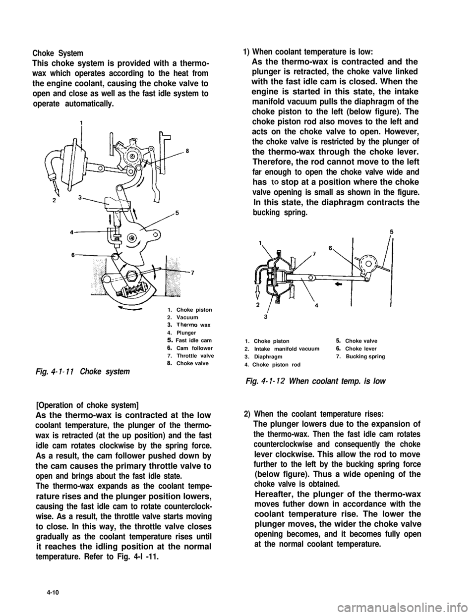
Choke System1) When coolant temperature is low:
This choke system is provided with a thermo-
wax which operates according to the heat from
the engine coolant, causing the choke valve to
open and close as well as the fast idle system to
operate automatically.
As the thermo-wax is contracted and the
plunger is retracted, the choke valve linked
with the fast idle cam is closed. When the
engine is started in this state, the intake
manifold vacuum pulls the diaphragm of the
choke piston to the left (below figure). The
choke piston rod also moves to the left and
acts on the choke valve to open. However,
the choke valve is restricted by the plunger of
the thermo-wax through the choke lever.
Therefore, the rod cannot move to the left
far enough to open the choke valve wide and
has .to stop at a position where the choke
valve opening is small as shown in the figure.
In this state, the diaphragm contracts the
bucking spring.
8
6
1.Choke piston2.Vacuum3.Therms wax
4.Plunger5. Fast idle cam
6.Cam follower7.Throttle valve8.Choke valve
Fig. 4- I- 11Choke system
[Operation of choke system]
As the thermo-wax is contracted at the low
coolant temperature, the plunger of the thermo-
wax is retracted (at the up position) and the fast
idle cam rotates clockwise by the spring force.
As a result, the cam follower pushed down by
the cam causes the primary throttle valve to
open and brings about the fast idle state.
The thermo-wax expands as the coolant tempe-
rature rises and the plunger position lowers,
causing the fast idle cam to rotate counterclock-
wise. As a result, the throttle valve starts moving
to close. In this way, the throttle valve closes
gradually as the coolant temperature rises until
it reaches the idling position at the normal
temperature. Refer to Fig. 4-l -11.
1.Choke piston
2.Intake manifoldvacuum
3.Diaphragm
4. Choke piston rod
5.Choke valve
6.Choke lever
7.Bucking spring
Fig. 4- I- 12 When coolant temp. is low
2) When the coolant temperature rises:
The plunger lowers due to the expansion of
the thermo-wax. Then the fast idle cam rotates
counterclockwise and consequently the choke
lever clockwise. This allow the rod to move
further to the left by the bucking spring force
(below figure). Thus a wide opening of the
choke valve is obtained.
Hereafter, the plunger of the thermo-wax
moves futher down in accordance with the
coolant temperature rise. The lower the
plunger moves, the wider the choke valve
opening becomes, and it becomes fully open
at the normal coolant temperature.
4-10
Page 128 of 962
0 Connect electric couplers securely.
l Connect accelerator cable to carburetor. With
the accelerator pedal released, adjust the cable
play to specification. This adjustment can be
made by turning the adjusting nut. After
adjustment, tighten the lock nut. Refer to
p. 4-19.
l Connect vacuum hoses securely.
l Refill cooling system.
l Connect negative cable at battery.
NOTE:
Upon completion of installation, be sure to
check each part for evidence of fuel leakage and
for proper operation. If defective, correct..
UNIT REPAIR OVERHAUL
This section outlines procedure to be used for
overhauling carburetor as removed from engine.
For removal and installation of carburetor from
and to engine, refer to the previous page.
NOTE:
l Be sure to replace gaskets as well as worn or
damaged parts.
l While disassembling and assembling carbure-
tor, use special care not to deform levers on
throttle valve shaft or cause damage to any
other parts.
l Don’t disassemble mixture control solenoid
valve and accelerator pump piston.
l Don’t remove idle and wide open micro
switches from the bracket where they are
installed.
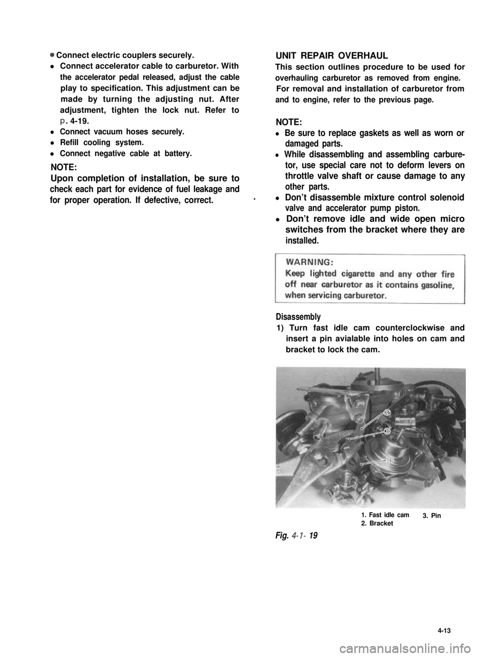
Disassembly
1) Turn fast idle cam counterclockwise and
insert a pin avialable into holes on cam and
bracket to lock the cam.
Fig. 4- I- 19
1. Fast idle cam
2. Bracket3. Pin
4-13
Page 134 of 962
16) Clamp wire harness securely.MAINTENANCE SERVICES
Fig. 4- l-39
1. Clamp
17) Remove the pin installed before disassemb-
ly (to lock fast idle cam).
Fig. 4- l-40
Before checking or adjusting the carburetor as
the cause of poor engine performance or rough
idle, check the followings for malconditions.
Ignition system including distributor, timing,
spark plugs and wires.
Air cleaner including thermostatically control-
led air cleaner system.
Evaporative emission control system.
PCV system.
EG R valve.
Engine compression.
Also, check the intake manifold, carburetor and
vacuum hoses for leakage.
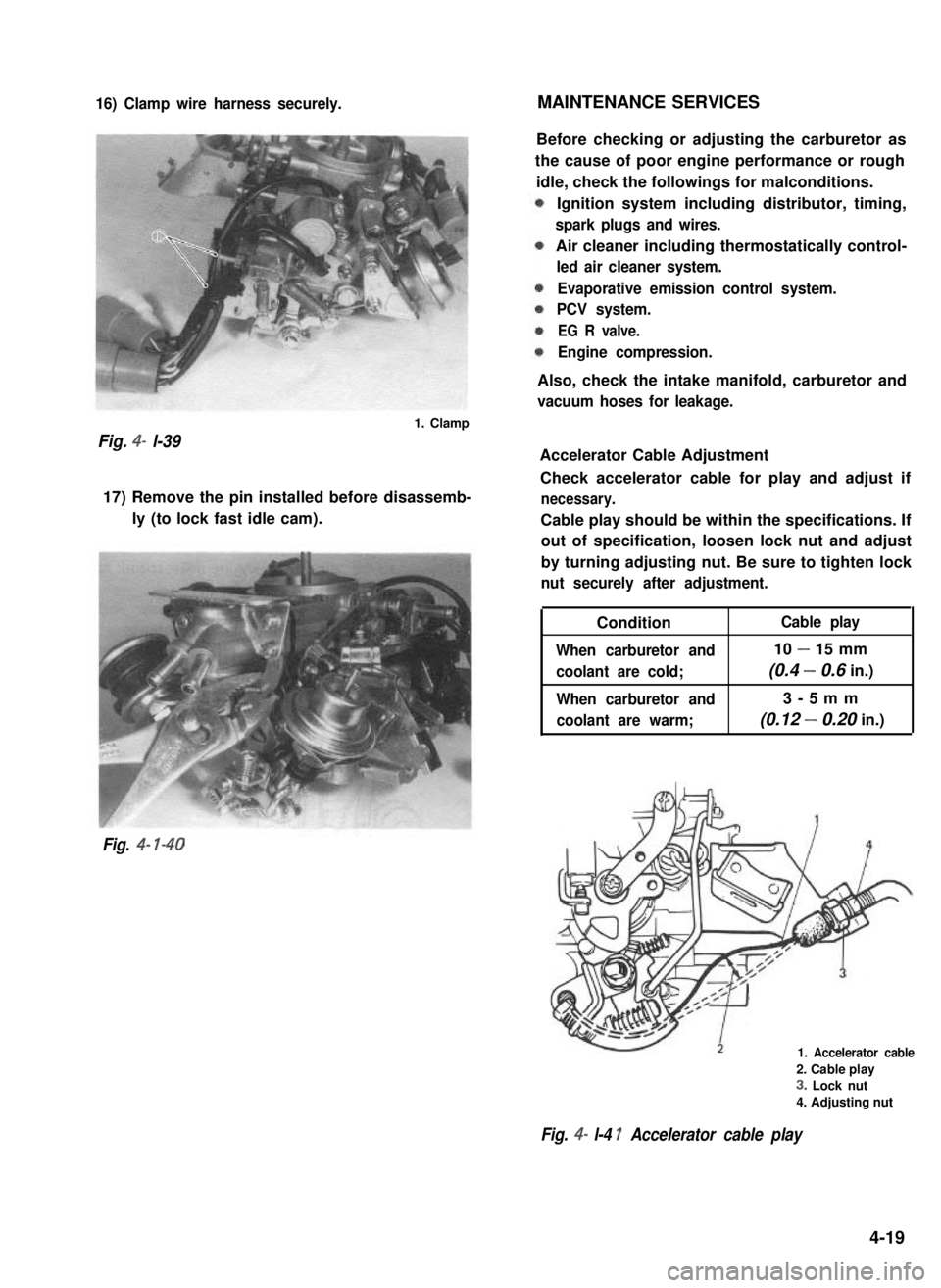
Accelerator Cable Adjustment
Check accelerator cable for play and adjust if
necessary.
Cable play should be within the specifications. If
out of specification, loosen lock nut and adjust
by turning adjusting nut. Be sure to tighten lock
nut securely after adjustment.
Condition
When carburetor and
coolant are cold;
When carburetor and
coolant are warm;
Cable play
10 - 15 mm
(0.4 - 0.6 in.)
3-5mm
(0.12 - 0.20 in.)
1. Accelerator cable
2. Cable play
3. Lock nut
4. Adjusting nut
Fig. 4- l-4 1 Accelerator cable play
4-19