Page 233 of 962
9-8. CLUTCH SWITCH
Install clutch switch in such a way that clearance
between thread end of clutch switch and clutch
pedal (distance 3 in Fig. 9-32)‘satisfies following
specification when clutch pedal is depressed
fully.
Tighten clutch switch lock nut to specified
torque.
Clutch switch thread
end-to-clutch pedall.O-1.5mm
clearance(0.04 - 0.06 in)
9- 12
Page 236 of 962

The alternator features a solid state regulator
that is mounted inside the alternator. All regula-
tor components are enclosed into a solid mold,
and this unit along with the brush holder assemb-
ly is attached to the slip ring end frame. The
regulator voltage setting cannot be adjusted.
The alternator rotor bearings contain enough
grease to eliminate the need for periodic lubri-
cation. Two brushes carry current through the
two slip rings to the field coil mounted on the
rotor, and under normal conditions will provide
long period of attention-free service.
The stator windings are assembled on the inside
of a laminated core that forms part of the
alternator frame. A rectifier bridge connected
to the stator windings contains six diodes,
and electrically changes the stator A.C. voltages
to a D.C. voltage which appears at the generator
output terminal.
The neutral diodes serve to convert the voltage
fluctuation at the neutral point to direct current
for increasing the alternator output.
A condenser mounted in the end frame protects
the diodes from high voltages and suppresses
radio noise.
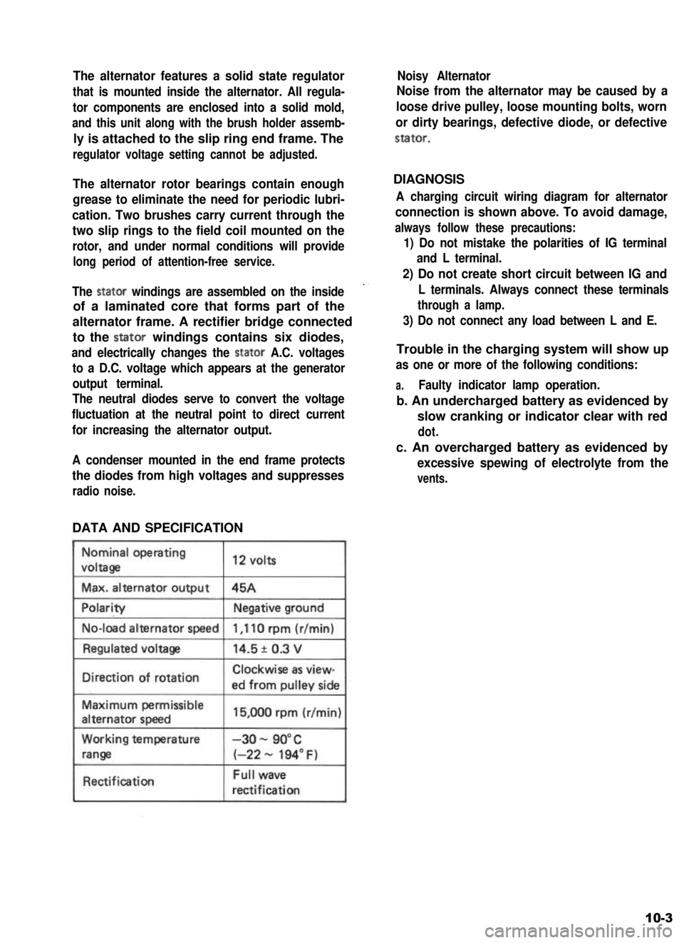
DATA AND SPECIFICATION
Nominal operating
voltaga
Max. alternator output
12 volts
45A
No-load alternator speed
IDirection of rotationClockwise as view-
ed from oullev side
Maximum permissible
alternator speed
Working temperature
range
Rectification
15,000 rpm (r/min)
-3o- 90°C
(-22 - 194” F)
Full wave
rectification
Noisy Alternator
Noise from the alternator may be caused by a
loose drive pulley, loose mounting bolts, worn
or dirty bearings, defective diode, or defective
stator.
DIAGNOSIS
A charging circuit wiring diagram for alternator
connection is shown above. To avoid damage,
always follow these precautions:
1) Do not mistake the polarities of IG terminal
and L terminal.
2) Do not create short circuit between IG and
L terminals. Always connect these terminals
through a lamp.
3) Do not connect any load between L and E.
Trouble in the charging system will show up
as one or more of the following conditions:
a.Faulty indicator lamp operation.
b. An undercharged battery as evidenced by
slow cranking or indicator clear with red
dot.
c. An overcharged battery as evidenced by
excessive spewing of electrolyte from the
vents.
10-3
Page 248 of 962
1.Clutch disc7.
No. 2 bushing
2. Clutch cover 8.
Clutch release shaft
3. Lock washer 9.
Return spring
4. Cover bolt 10.
No. 1 bushing
5.Clutch releasebearing11.Shaft seal
8.
Clutch release fork pin 12. Shaft cowr
Fig. 1 l-2
11-3
Page 253 of 962

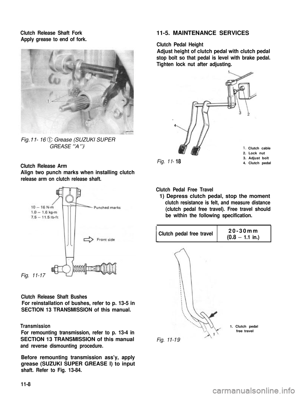
Clutch Release Shaft Fork
Apply grease to end of fork.
Fig. I l- 16 @ Grease (SUZUKI SUPER
GREASE “‘A “)
Clutch Release Arm
Align two punch marks when installing clutch
release arm on clutch release shaft.
Fig. 11-17
Clutch Release Shaft Bushes
For reinstallation of bushes, refer to p. 13-5 in
SECTION 13 TRANSMISSION of this manual.
Transmission
For remounting transmission, refer to p. 13-4 in
SECTION 13 TRANSMISSION of this manual
and reverse dismounting procedure.
11-5. MAINTENANCE SERVICES
Clutch Pedal Height
Adjust height of clutch pedal with clutch pedal
stop bolt so that pedal is level with brake pedal.
Tighten lock nut after adjusting.
.
4
I-
I- 18
1. Clutch cable2. Lock nut3. Adjust bolt4. Clutch pedalFig. 1
Clutch Pedal Free Travel
1) Depress clutch pedal, stop the moment
clutch resistance is felt, and measure distance
(clutch pedal free travel). Free travel should
be within the following specification.
!Clutch pedal free travel20-30mm
(0.8 - 1.1 in.)c
Fig. 1
1. Clutch pedalfree travel
Before remounting transmission ass’y, apply
grease (SUZUKI SUPER GREASE I) to input
shaft. Refer to Fig. 13-84.
11-8
Page 261 of 962

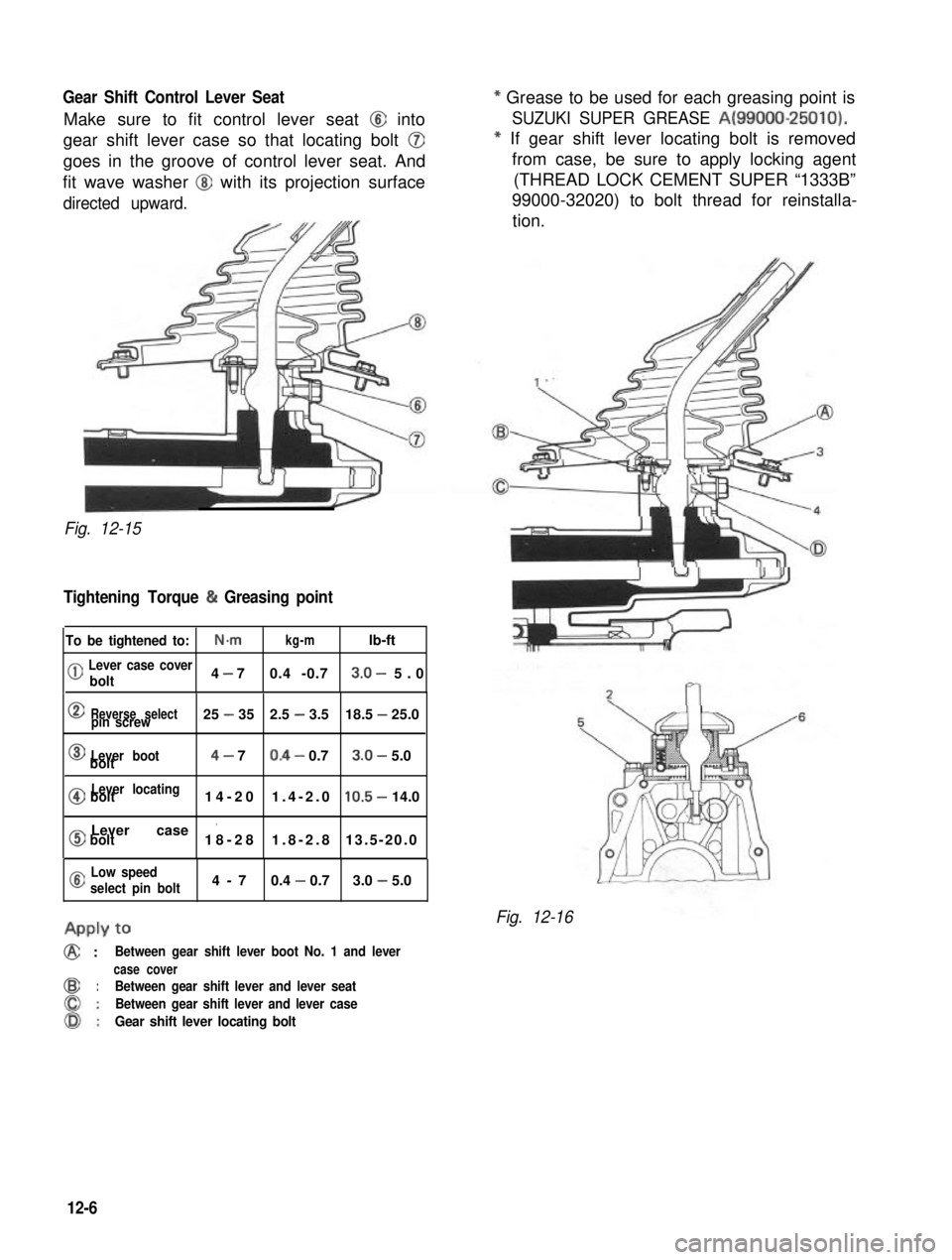
Gear Shift Control Lever Seat
Make sure to fit control lever seat @I into
gear shift lever case so that locating bolt @
goes in the groove of control lever seat. And
fit wave washer @J with its projection surface
directed upward.
--
Fig. 12-15
Tightening Torque (h Greasing point
To be tightened to:N-mkg-mlb-ft
(jj Lever case cover
bolt4 - 70.4 -0.73.0- 5.0
0Reverse selectpin screw25 - 352.5 - 3.518.5 - 25.0
0Lever bootbolt4- 70.4- 0.73.0- 5.0
@Lever locatingbolt14-201.4-2.010.5- 14.0
0Lever case ’bolt18-281.8-2.813.5-20.0
a Low speed
select pin bolt4-70.4 - 0.73.0 - 5.0
APPLY to
@ :Between gear shift lever boot No. 1 and lever
case cover
@:Between gear shift lever and lever seat
Between gear shift lever and lever case
Gear shift lever locating bolt
* Grease to be used for each greasing point is
SUZUKI SUPER GREASE A(99000-25010).
* If gear shift lever locating bolt is removed
from case, be sure to apply locking agent
(THREAD LOCK CEMENT SUPER “1333B”
99000-32020) to bolt thread for reinstalla-
tion.
Fig. 12-16
12-6
Page 265 of 962

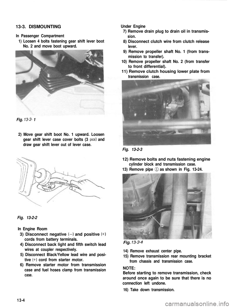
13-3. DISMOUNTINGIn Passenger Compartment
1) Loosen 4 bolts fastening gear shift lever boot
No. 2 and move boot upward.
Fig.
13-2- 1 Under Engine
7) Remove drain plug to drain oil in transmis-
sion.
8) Disconnect clutch wire from clutch release
lever.
9) Remove propeller shaft No. 1 (from trans-
mission to transfer).
10) Remove propeller shaft No. 2 (from transfer
to front differential).
11) Remove clutch housing lower plate from
transmission case.
2) Move gear shift boot No. 1 upward. Loosen
gear shift lever case cover bolts (3
PCS) and
draw gear shift lever out of lever case.
Fig. 13-2-3
Fig. 13-2-2 In Engine Room
3) Disconnect negative (-) and positive (+)
cords from battery terminals.
4) Disconnect back light and fifth switch lead
wires at coupler respectively.
5) Disconnect Black/Yellow lead wire and posi- tive
(+) cord from starter motor.
6) Remove starter motor from transmission
case and fuel hoses clamp from transmission
case.
12) Remove bolts and nuts fastening engine
cylinder block and transmission case.
13) Remove pipe (iJ as shown in Fig. 13-24.
Fig. 13-2-4
14) Remove exhaust center pipe.
15) Remove transmission rear mounting bracket
from chassis and transmission case.
NOTE:
Before starting to remove transmission, check
around once again to be sure that there is no
connection left undone.
16) Take down transmission.
13-4
Page 272 of 962
2) Using the same special tool (C), mentioned
above, drive out yoke pin on high speed
gear shift fork, and pull out shift shaft.
As in above case, be careful not to let
locating ball, interlock ball and spring fly
away.
1 CAUTION:
3) Drive yoke pin out of low speed gear shift
fork as in above step 2) and pull out fork
shaft and fork.
When removing yoke pin, be sure not to
drive it out so far as to contact case. Or it
will cause damage to case.
Fig. 13-27
Fig. 13-25
Fig. 13-28
Fig. 13-26
13-11
Page 281 of 962
Fig. 13-63@High and reverse gear shift fork
@Low speed gear shift fork
NOTE:
Gear shift fork
the same.
*eFig. 13-65
Note that 3 shift shafts individually have a
locating ball and locating spring, and that 2
interlock balls and an interlock roller are used
between shafts as shown in Fig. 1364.
Fig. 13-64
Install low, high and reverse shafts in that order.
1) Install 3 locating springs into 3 holes in
upper case.Fit locating ball ( @ in Fig.
13-64) on top of locating spring in hole.
1. Locating spring2. Locating ball @3. Upper case
2) Insert low speed gear shift shaft into upper
case and low speed shift fork in the direction
as shown in Fig. 1366.
9-r
Fig. 13-66
3) As shown below, push down low speed gear
shift shaft locating ball to pass shaft over it
and keep inserting shaft until locating ball
fits in center slot of 3 continuous slots in
shaft.
Drive shift yoke pin into fork and shaft.
13-20