Page 95 of 962
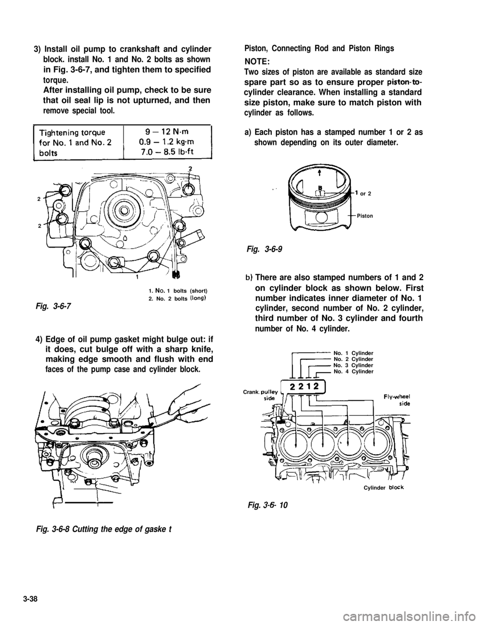
3) Install oil pump to crankshaft and cylinder
block. install No. 1 and No. 2 bolts as shown
in Fig. 3-6-7, and tighten them to specified
torque.
After installing oil pump, check to be sure
that oil seal lip is not upturned, and then
remove special tool.
-
2
2
Fig. 3-6-7
1. NO. 1 bolts (short)
2. No. 2 bolts (long)
Piston, Connecting Rod and Piston Rings
NOTE:
Two sizes of piston are available as standard size
spare part so as to ensure proper piston-to-
cylinder clearance. When installing a standard
size piston, make sure to match piston with
cylinder as follows.
a) Each piston has a stamped number 1 or 2 as
shown depending on its outer diameter.
or 2
Piston
Fig. 3-6-9
b) There are also stamped numbers of 1 and 2
on cylinder block as shown below. First
number indicates inner diameter of No. 1
cylinder, second number of No. 2 cylinder,
third number of No. 3 cylinder and fourth
number of No. 4 cylinder.
4) Edge of oil pump gasket might bulge out: if
it does, cut bulge off with a sharp knife,
making edge smooth and flush with end
faces of the pump case and cylinder block.
Crank
No. 1 CylinderNo. 2 CylinderNo. 3 CylinderNo. 4 Cylinder
Cylinder block
Fig. 3-6- 10
Fig. 3-6-8 Cutting the edge of gaske t
3-38
Page 98 of 962
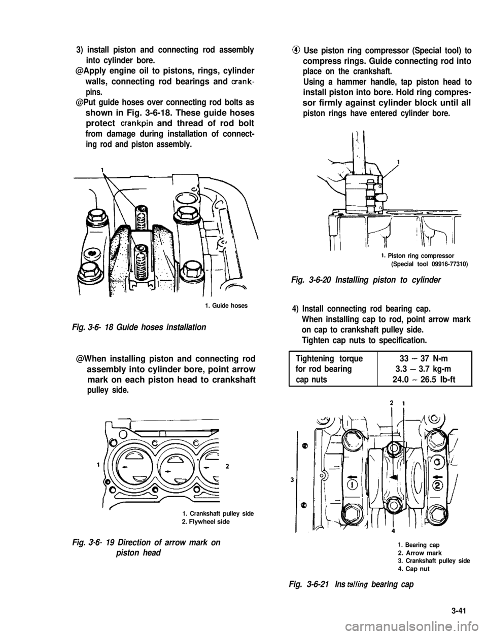
3) install piston and connecting rod assembly
into cylinder bore.
@Apply engine oil to pistons, rings, cylinder
walls, connecting rod bearings and crank-
pins.
@Put guide hoses over connecting rod bolts as
shown in Fig. 3-6-18. These guide hoses
protect crankpin and thread of rod bolt
from damage during installation of connect-
ing rod and piston assembly.
1. Guide hoses
Fig. 3-6- 18 Guide hoses installation
@When installing piston and connecting rod
assembly into cylinder bore, point arrow
mark on each piston head to crankshaft
pulley side.
1. Crankshaft pulley side
2. Flywheel side
Fig. 3-6- 19 Direction of arrow mark on
piston head
@ Use piston ring compressor (Special tool) to
compress rings. Guide connecting rod into
place on the crankshaft.
Using a hammer handle, tap piston head to
install piston into bore. Hold ring compres-
sor firmly against cylinder block until all
piston rings have entered cylinder bore.
1. Piston ring compressor
(Special tool 09916-77310)
Fig. 3-6-20 Installing piston to cylinder
4) Install connecting rod bearing cap.
When installing cap to rod, point arrow mark
on cap to crankshaft pulley side.
Tighten cap nuts to specification.
Tightening torque33-37 N-m
for rod bearing3.3-3.7 kg-m
cap nuts24.0-26.5 lb-ft
1. Bearing cap
2. Arrow mark3. Crankshaft pulley side
4. Cap nut
Fig. 3-6-21Ins tailing bearing cap
3-41
Page 99 of 962
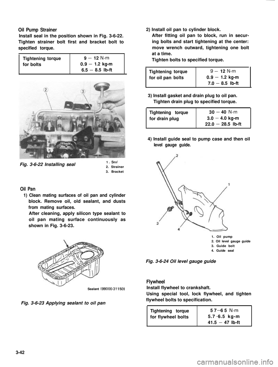
Oil Pump Strainer
Install seal in the position shown in Fig. 3-6-22.
Tighten strainer bolt first and bracket bolt to
specified torque.
Tighteningtorque9-12 N.m
0.9-for bolts1.2 kg-m
6.5 -8.5 lb-ft
Fig. 3-6-22 Installing seal1. Seal
2. Strainer
3. Bracket
Oil Pan
1) Clean mating surfaces of oil pan and cylinder
block. Remove oil, old sealant, and dusts
from mating surfaces.
After cleaning, apply silicon type sealant to
oil pan mating surface continuously as
shown in Fig. 3-6-23.
Sealant MOOO-31150)
Fig. 3-6-23 Applying sealant to oil pan
2) Install oil pan to cylinder block.
After fitting oil pan to block, run in secur-
ing bolts and start tightening at the center:
move wrench outward, tightening one bolt
at a time.
Tighten bolts to specified torque.
Tighteningtorque9-12 N-m
-for oil panbolts0.91.2 kg-m
7.0 -8.5 lb-ft
3) Install gasket and drain plug to oil pan.
Tighten drain plug to specified torque.
Tightening torque
for drain plug
30-40 N.m
3.0-4.0 kg-m
22.0-28.5 lb-ft
4) Install guide seal to pump case and then oil
level gauge guide.
1. Oil pump2. Oil level gauge guide
3. Guide bolt
4. Guide seal
Fig. 3-6-24 Oil level gauge guide
Flywheel
Install flywheel to crankshaft.
Using special tool, lock flywheel, and tighten
flywheel bolts to specification.
Tightening torque
for flywheel bolts
57 65 N-m-
5.7 6.5 kg-m-
41.5 - 47 lb-ft
3-42
Page 102 of 962
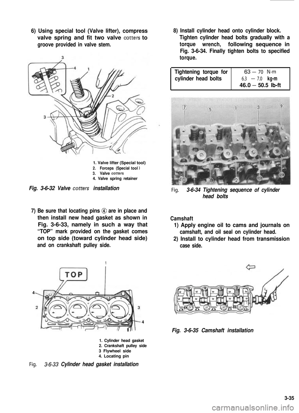
6) Using special tool (Valve lifter), compress
valve spring and fit two valve totters to
groove provided in valve stem.
1. Valve lifter (Special tool)
2.Forceps (Specialtool13.Valve totters4. Valve spring retainer
Fig. 3-6-32 Valve totters installation
7) Be sure that locating pins @ are in place and
then install new head gasket as shown in
Fig. 3-6-33, namely in such a way that
“TOP” mark provided on the gasket comes
on top side (toward cylinder head side)
and on crankshaft pulley side.
1
4
4
1. Cylinder head gasket2. Crankshaft pulley side
3 Flywheel side4. Locating pin
Fig. 3-6-33 Cylinder head gasket installation
8) Install cylinder head onto cylinder block.
Tighten cylinder head bolts gradually with a
torquewrench,following sequence in
Fig. 3-6-34. Finally tighten bolts to specified
torque.
Tightening torque for63-70 N-m
cylinder head bolts6.3-7.0 kg-m
46.0 -50.5 lb-ft
Fig. 3-6-34 Tightening sequence of cylinder
head bolts
Camshaft
1) Apply engine oil to cams and journals on
camshaft, and oil seal on cylinder head.
2) Install to cylinder head from transmission
case side.
Fig. 3-6-35 Camshaft installation
3-35
Page 103 of 962
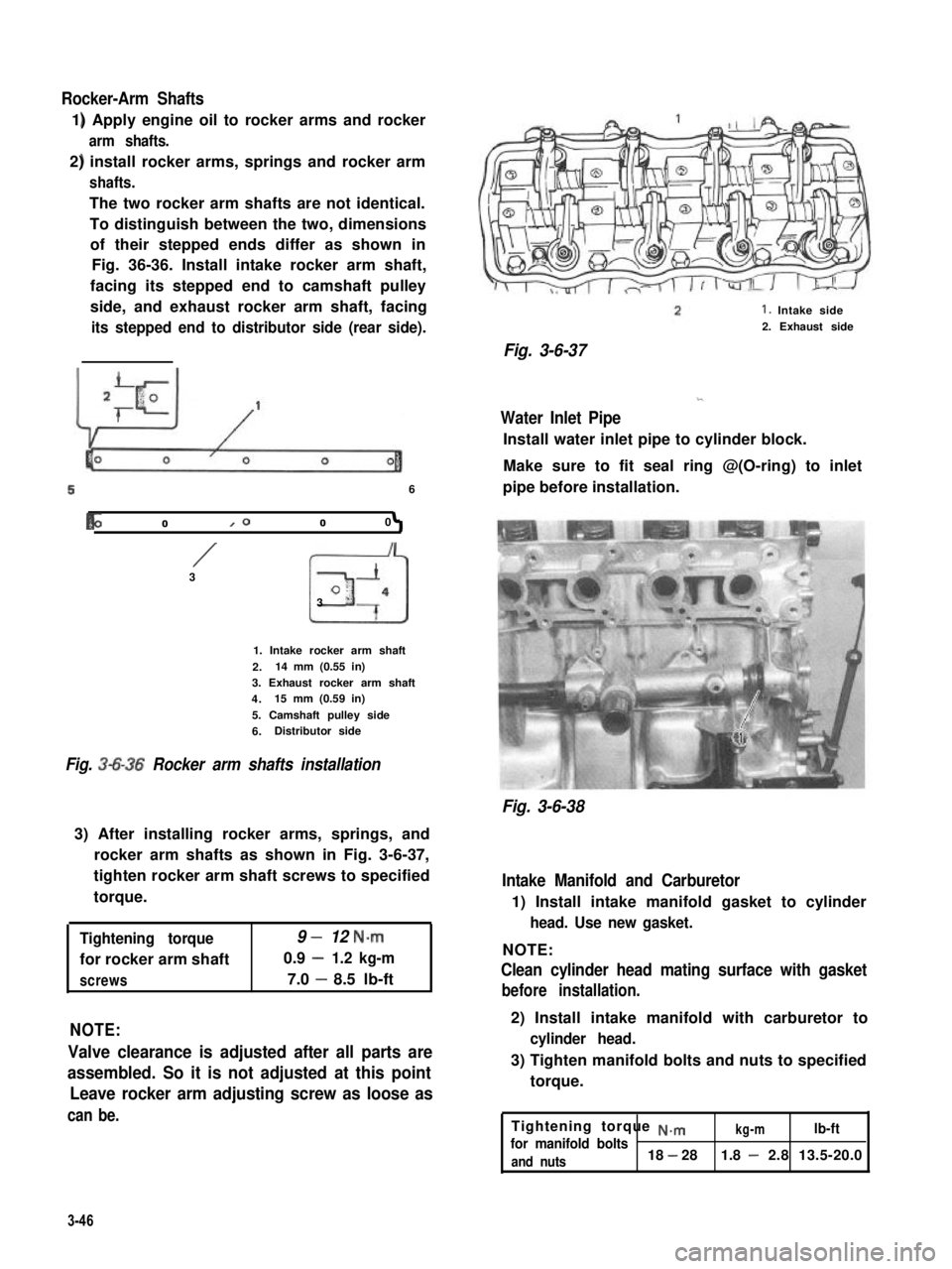
Rocker-Arm Shafts
1) Apply engine oil to rocker arms and rocker
arm shafts.
2) install rocker arms, springs and rocker arm
shafts.
The two rocker arm shafts are not identical.
To distinguish between the two, dimensions
of their stepped ends differ as shown in
Fig. 36-36. Install intake rocker arm shaft,
facing its stepped end to camshaft pulley
side, and exhaust rocker arm shaft, facing
its stepped end to distributor side (rear side).
56
b01000
/3
I
3
I
o-
“7
1. Intake rocker arm shaft
2.14 mm (0.55 in)
3. Exhaust rocker arm shaft
4.15 mm (0.59 in)
5. Camshaft pulley side
6.Distributor side
Fig. 3-6-36 Rocker arm shafts installation
3) After installing rocker arms, springs, and
rocker arm shafts as shown in Fig. 3-6-37,
tighten rocker arm shaft screws to specified
torque.
Tightening torque9 -12 N.m
for rocker arm shaft0.9 -1.2 kg-m
screws7.0 -8.5 lb-ft
NOTE:
Valve clearance is adjusted after all parts are
assembled. So it is not adjusted at this point
Leave rocker arm adjusting screw as loose as
can be.
1. Intake side
2. Exhaust side
Fig. 3-6-37
Water Inlet Pipe
Install water inlet pipe to cylinder block.
Make sure to fit seal ring @(O-ring) to inlet
pipe before installation.
Fig. 3-6-38
Intake Manifold and Carburetor
1) Install intake manifold gasket to cylinder
head. Use new gasket.
NOTE:
Clean cylinder head mating surface with gasket
before installation.
2) Install intake manifold with carburetor to
cylinder head.
3) Tighten manifold bolts and nuts to specified
torque.
Tightening torque ~.mkg-mlb-ftfor manifold bolts
and nuts18 - 281.8 - 2.8 13.5-20.0
3-46
Page 104 of 962
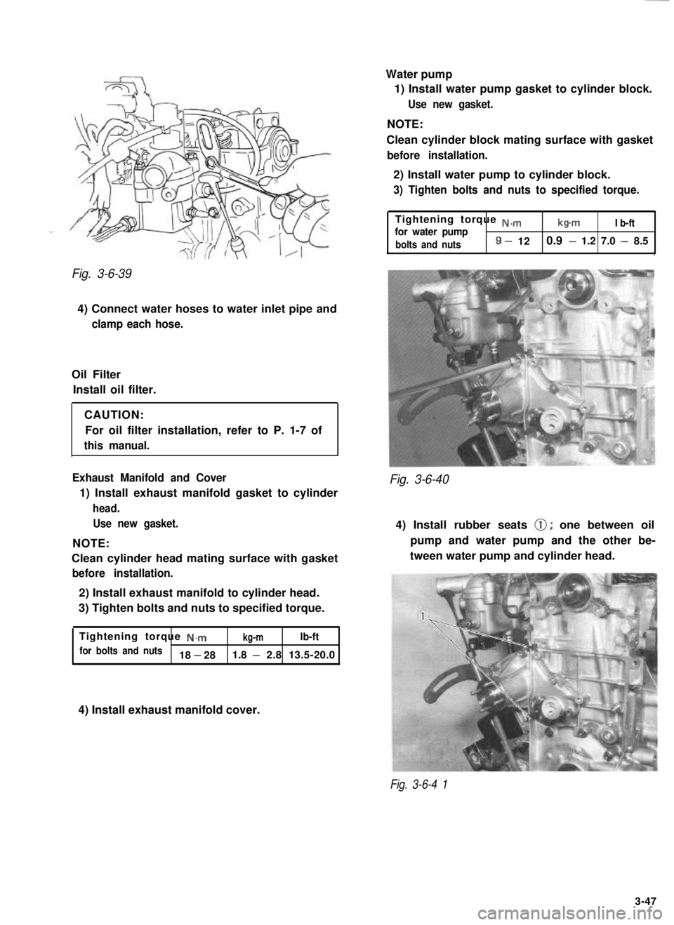
Fig. 3-6-39
4) Connect water hoses to water inlet pipe and
clamp each hose.
Oil FilterInstall oil filter.
CAUTION:For oil filter installation, refer to P. 1-7 of
this manual.
Exhaust Manifold and Cover
1) Install exhaust manifold gasket to cylinder
head. Use new gasket.
NOTE:
Clean cylinder head mating surface with gasket
before installation.
2) Install exhaust manifold to cylinder head.
3) Tighten bolts and nuts to specified torque.
Tightening torque
N.mkg-mlb-ft
for bolts and nuts18 - 28 1.8 - 2.8 13.5-20.0 Water pump
1) Install water pump gasket to cylinder block.
Use new gasket.
NOTE:
Clean cylinder block mating surface with gasket
before installation.
2) Install water pump to cylinder block.
3) Tighten bolts and nuts to specified torque.
Tightening torque N.m
for water pumpb-mI b-ft
bolts and nuts
8 - 12 0.9 - 1.2 7.0 - 8.5,
Fig. 3-6-40
4) Install rubber seats 0; one between oil
pump and water pump and the other be-
tween water pump and cylinder head.
4) Install exhaust manifold cover.
Fig. 3-6-4 1
3-47
Page 106 of 962
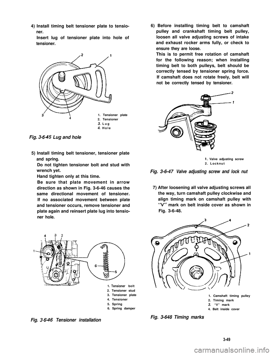
4) Install timing belt tensioner plate to tensio-
ner.
Insert lug of tensioner plate into hole of
tensioner.
3w1. Tensioner plate42. Tensioner
3. Lug4. Hole
Fig. 3-645 Lug and hole
5) Install timing belt tensioner, tensioner plate
and spring.
Do not tighten tensioner bolt and stud with
wrench yet.
Hand tighten only at this time.
Be sure that plate movement in arrow
direction as shown in Fig. 3-6-46 causes the
same directional movement of tensioner.
If no associated movement between plate
and tensioner occurs, remove tensioner and
plate again and reinsert plate lug into tensio-
ner hole.
1. bolt
2. Tensioner stud3. Tensioner plate
4. Tensioner
5. Spring6. Spring damper
Fig. 3-646 Tensioner installation
6) Before installing timing belt to camshaft
pulley and crankshaft timing belt pulley,
loosen all valve adjusting screws of intake
and exhaust rocker arms fully, or check to
ensure they are loose.
This is to permit free rotation of camshaft
for the following reason; when installing
timing belt to both pulleys, belt should be
correctly tensed by tensioner spring force.
If camshaft does not rotate freely, belt will
not be correctly tensed by tensioner.
1. Valve adjusting screw
2. Locknut
Fig. 3-6-47Valve adjusting screw and lock nut
7) After loosening all valve adjusting screws all
the way, turn camshaft pulley clockwise and
align timing mark on camshaft pulley with
“V” mark on belt inside cover as shown in
Fig. 3-6-48.
1. Camshaft timing pulley
2. Timing mark
3.“V” mark4. Belt inside cover
Fig. 3-648 Timing marks
3-49
Tensioner
Page 107 of 962
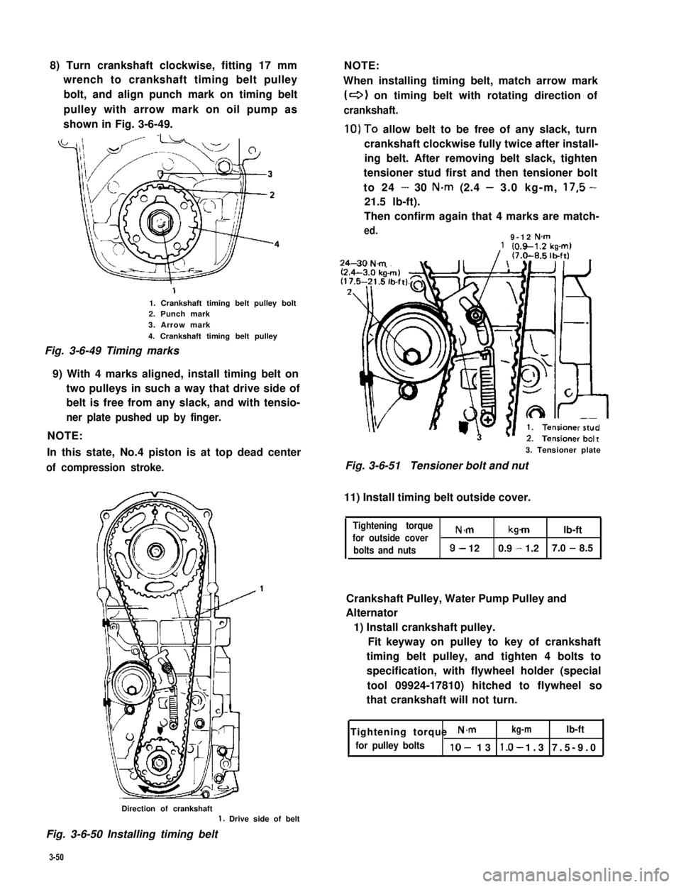
8) Turn crankshaft clockwise, fitting 17 mm
wrench to crankshaft timing belt pulley
bolt, and align punch mark on timing belt
pulley with arrow mark on oil pump as
shown in Fig. 3-6-49.
1. Crankshaft timing belt pulley bolt2. Punch mark3. Arrow mark
4. Crankshaft timing belt pulley
Fig. 3-6-49 Timing marks
9) With 4 marks aligned, install timing belt on
two pulleys in such a way that drive side of
belt is free from any slack, and with tensio-
ner plate pushed up by finger.
NOTE:
In this state, No.4 piston is at top dead center
of compression stroke.
NOTE:
When installing timing belt, match arrow mark
(+I on timing belt with rotating direction of
crankshaft.
10)To allow belt to be free of any slack, turn
crankshaft clockwise fully twice after install-
ing belt. After removing belt slack, tighten
tensioner stud first and then tensioner bolt
to 24 - 30 N.m (2.4 - 3.0 kg-m, 17,5 -
21.5 lb-ft).
Then confirm again that 4 marks are match-
ed.9-12 N-m
3. Tensioner plate
Fig. 3-6-51Tensioner bolt and nut
11) Install timing belt outside cover.
Tightening torque
for outside coverN.mkmlb-ft
bolts and nuts9- 120.9 - 1.27.0 - 8.5
Crankshaft Pulley, Water Pump Pulley and
Alternator
1) Install crankshaft pulley.
Fit keyway on pulley to key of crankshaft
timing belt pulley, and tighten 4 bolts to
specification, with flywheel holder (special
tool 09924-17810) hitched to flywheel so
that crankshaft will not turn.
Tightening torque N.mkg-mlb-ft
for pulley boltslo- 13 1.3 7.5-9.0*
Direction of crankshaft1. Drive side of belt
Fig. 3-6-50 Installing timing belt
3-50