Page 282 of 962

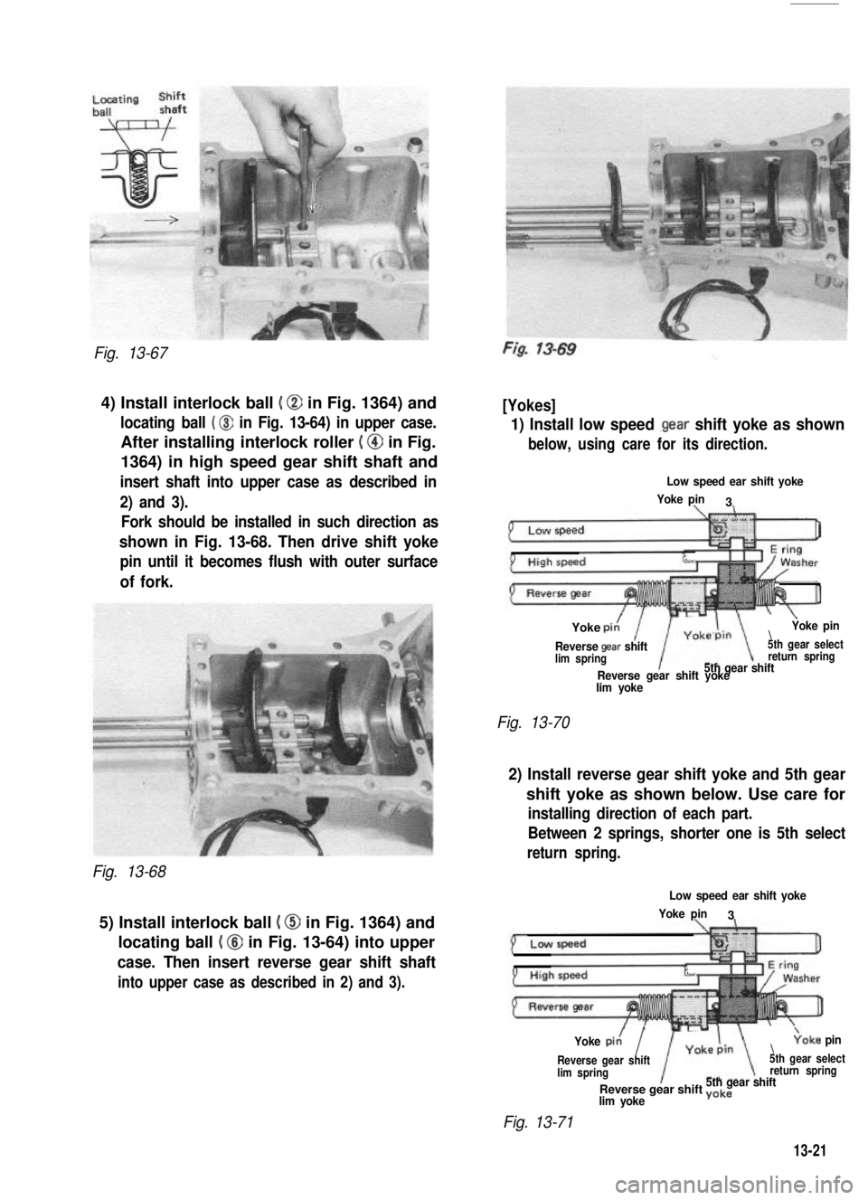
Fig. 13-67
4) Install interlock ball ( @ in Fig. 1364) and
locating ball ( @ in Fig. 13-64) in upper case.
After installing interlock roller ( @ in Fig.
1364) in high speed gear shift shaft and
insert shaft into upper case as described in
2) and 3).
Fork should be installed in such direction as
shown in Fig. 13-68. Then drive shift yoke
pin until it becomes flush with outer surface
of fork.
Fig. 13-68
5) Install interlock ball ( @ in Fig. 1364) and
locating ball ( @ in Fig. 13-64) into upper
case. Then insert reverse gear shift shaft
into upper case as described in 2) and 3).
[Yokes]
1) Install low speed .gear shift yoke as shown
below, using care for its direction.
Low speed ear shift yoke
Yoke pin3
%-JJ
Yoke pit!\
\Yoke pin
Reverse gaar shift5th gear selectlim springreturn spring5th gear shiftReverse gear shift yokelim yoke
Fig. 13-70
2) Install reverse gear shift yoke and 5th gear
shift yoke as shown below. Use care for
installing direction of each part.
Between 2 springs, shorter one is 5th select
return spring.
Low speed ear shift yoke
Yoke pin3
Yoke pi,/I\;oke pin
Reverse gear shift5th gear selectlim springreturn spring5th gear shiftReverse gear shift yokelim yoke
Fig. 13-71
13-21
Page 285 of 962

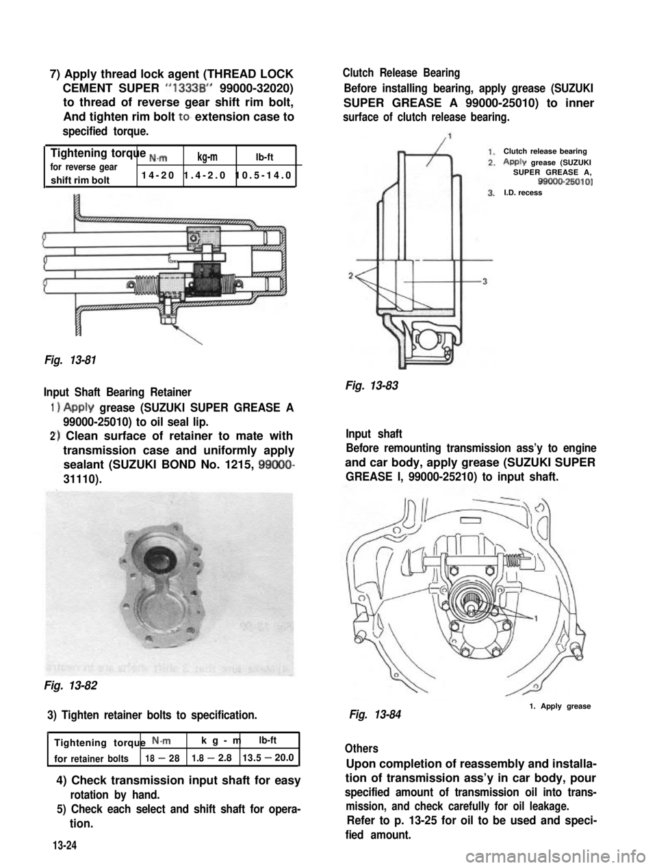
7) Apply thread lock agent (THREAD LOCK
CEMENT SUPER “1333B” 99000-32020)
to thread of reverse gear shift rim bolt,
And tighten rim bolt to. extension case to
specified torque.
Tightening torque ,,,”kg-mlb-ftfor reverse gear
shift rim bolt14-20 1.4-2.0 10.5-14.0
\
Fig. 13-81
Input Shaft Bearing Retainer
1
2
)Apply grease (SUZUKI SUPER GREASE A
99000-25010) to oil seal lip.
‘) Clean surface of retainer to mate with
transmission case and uniformly apply
sealant (SUZUKI BOND No. 1215, 99000-
31110).
Fig. 13-82
3) Tighten retainer bolts to specification.
h
Tightening torque N*mkg-mlb-ft
forretainerbolts18-281.8-2.813.5-20.0
4) Check transmission input shaft for easy
rotation by hand.
5) Check each select and shift shaft for opera-
tion.
Clutch Release Bearing
Before installing bearing, apply grease (SUZUKI
SUPER GREASE A 99000-25010) to inner
surface of clutch release bearing.
Fig. 13-83
Clutch release bearing
Apply grease (SUZUKISUPER GREASE A,99000-25010)I.D. recess
Input shaft
Before remounting transmission ass’y to engine
and car body, apply grease (SUZUKI SUPER
GREASE I, 99000-25210) to input shaft.
Fig. 13-841. Apply grease
Others
Upon completion of reassembly and installa-
tion of transmission ass’y in car body, pour
specified amount of transmission oil into trans-
mission, and check carefully for oil leakage.
Refer to p. 13-25 for oil to be used and speci-
fied amount.13-24
Page 289 of 962

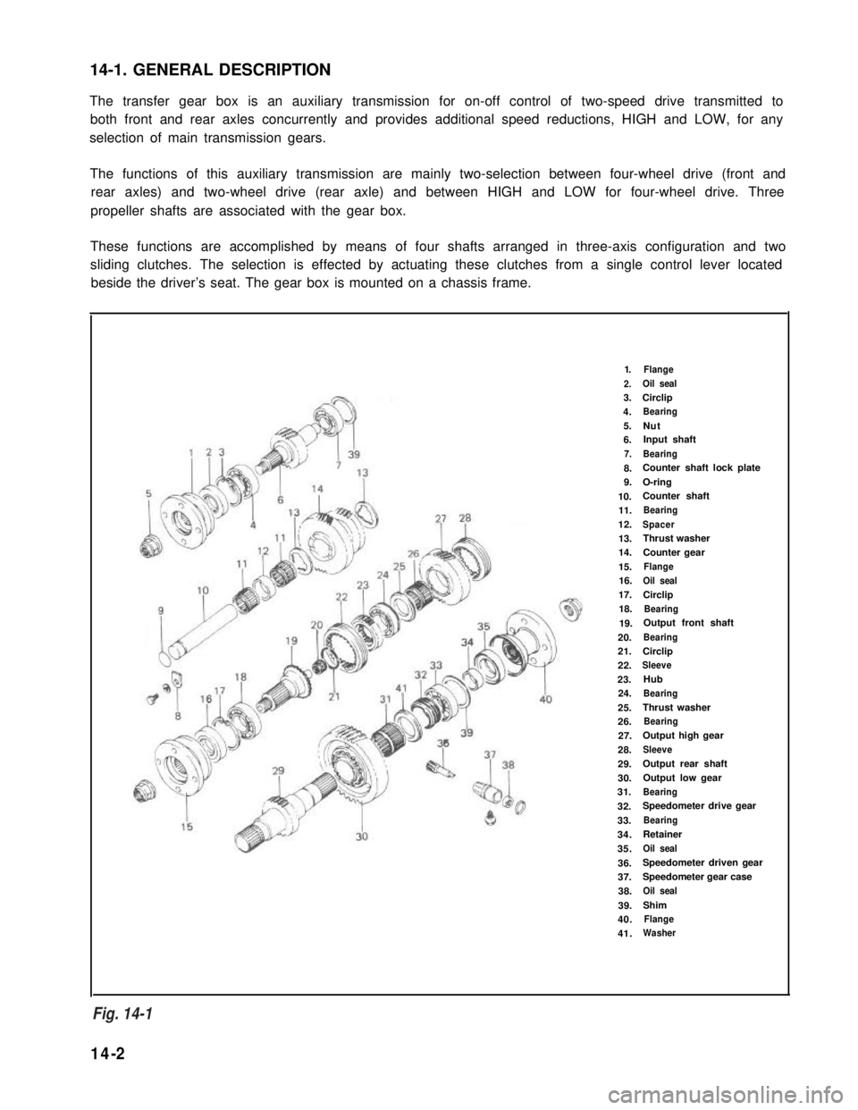
14-1. GENERAL DESCRIPTION
The transfer gear box is an auxiliary transmission for on-off control of two-speed drive transmitted to
both front and rear axles concurrently and provides additional speed reductions, HIGH and LOW, for any
selection of main transmission gears.
The functions of this auxiliary transmission are mainly two-selection between four-wheel drive (front and
rear axles) and two-wheel drive (rear axle) and between HIGH and LOW for four-wheel drive. Three
propeller shafts are associated with the gear box.
These functions are accomplished by means of four shafts arranged in three-axis configuration and two
sliding clutches. The selection is effected by actuating these clutches from a single control lever located
beside the driver’s seat. The gear box is mounted on a chassis frame.
1.Flange
2.Oil seal
3.Circlip
4.Bearing
5.Nut6.Input shaft
7.Bearing
8.Counter shaft lock plate
9.O-ring
10.Counter shaft
11.Bearing
12.Spacer
13.Thrust washer
14.Counter gear
15.Flange
16.Oil seal
17.Circlip
18.Bearing
19.Output front shaft
20.Bearing
21.Circlip
22.Sleeve
23.Hub
24.Bearing
25.Thrust washer
26.Bearing
27.Output high gear
28.Sleeve
29.Output rear shaft
30.Output low gear
31.Bearing
32.Speedometer drive gear
33.Bearing
34.Retainer
35.Oil seal
36.Speedometer driven gear
37.Speedometer gear case
38.Oil seal
39.Shim
40.Flange
41.Washer
Fig. 14- 1
14-2
Fig. 14-1
Page 293 of 962
14-5. REMOVAL
1) Lift up car and remove securing bolts from
each universal-joint flange connection to
sever 3 propeller shafts from transfer gear
box.
Fig. 14-5
2) Remove clamp @ and boot @ from transfer
gear box.
Fig. 14-7
4) Drain out oil from gear box by loosening
its drainplug.
Fig. 14-8
5) Disconnect speedometer drive cable from
transfer gear box.
Transfer‘gear case
Fig. 14-6
3) Twist control lever guide counterclockwise
while pushing it down; this will permit lever
to be removed from gear box.
14-6
Fig. 14-8
Fig. 14-9
Page 295 of 962
14-6. DISASSEMBLY
Universal-Joint Yoke Flanges
There are 3 flanges to be removed: one from
input shaft and other from output front and rear
shafts. Lock flange so that it will not turn, and
loosen and remove nut holding flange to the
shaft. Draw off flange.
Fig. 14-12 @ Special tool (09930401131
Speedometer Driven Gear
Loosen speedometerdriven gear case bolt
and remove speedometer driven gear case with
gear.
Transfer Front Case
Remove the indicator light switch from front
case.
NOTE:
Use care not to lose switch ball. This ball is
larger than interlock ball and locating balls.
Fig. 14-16
Remove bolts securing transfer front case,
and take off case.
By tapping output front shaft with a plastic
hammer,remove output front shaft from
front case.
Fig. 14-18
Fig. 14-15
14-8
Fig. 14-17
Page 297 of 962
2) Using spring pin remover (special tool), drive
2 spring pins out of front drive shift shaft
@ and reduction shift shaft 0.
Spring pin remover @ : (09922-85811).
Fig. 14-24
3) Remove forks and shift shafts.
NOTE:
At this time, locating ball and spring will jump
out of hole, use care not to lose them.
Fig. 14-25
4) Hammer output rear shaft with a plastic
hammer to drive it out of center case.
5) Pull out counter gear,
Remove counter shaft
loosening counter shaft
bearings and spacer.
from center case by
lock plate bolt.
Fig. 14-27
6) Remove input shaft from center case by
hammering thick part of case or input
shaft center with a plastic hammer.
Fig. 14-28
14-10
Fig. 14-26
Page 305 of 962
Rear Case
1) Install oil seal in rear case and apply grease
to oil seal lip.
Center Case
1) Install input shaft front bearing circlip and
oil seal in center case.
Snap ring pliers @ : (09900~6108)
Fig. 14-49
Fig. 14-51
2) Install counter shaft thrust washer to rear
case, bringing its face without depressions
against case and fit its bent portion securely
into groove in case.
NOTE:
Apply ample amount of grease to both surfaces
of washer so as to lubricate sliding surfaces and
prevent washer from moving out of place or
slipping off.
Fig. 14-50
2) Install input shaft to center case.
Fig. 14-52
3) After greasing 0 ring on counter shaft,
insert shaft into center case and secure
shaft with lock plate and bolt.
Fig. 14-53
Fig. 14-50
14-18
Fig. 14-53
Fig. 14-52
Page 306 of 962
4) Install the counter shaft thrust washer to
center case. For installation, apply ample
amount of grease to both faces of the washer
so as to lubricate sliding surfaces and prevent
it from moving out of place or slipping off
and bring its face without depressions against
center case, and fit its bent portion into
groove in case securely.
Fig. 14-54
5) Install needle roller bearings, spacer and
counter gear on counter shaft.
Fig. 14-55
6) Install output shaft assembly to center case.
Fig. 14-56
7) When installing front drive shift shaft and
reduction shift shaft in center case, install
spring 0, ball 0, shaft 0, ball @, shaft
0, ball 8, spring 0 and plug 8. in that
order.
d 18-3ON.m
Fig. 14-57(1.8 - 3.0 kg-m 1(13.5 - 21.5 lb-ft)
8) Fit forks on shift shafts and lock them
with spring pins. Forks should be fitted in
correct direction according to below figure.
Fig. 14-58
14-19
Fig. 14-54
Fig. 14-55
Fig. 14-58
Fig. 14-57
Fig. 14-56
14-19