1987 SUZUKI GRAND VITARA check engine
[x] Cancel search: check enginePage 45 of 962
9
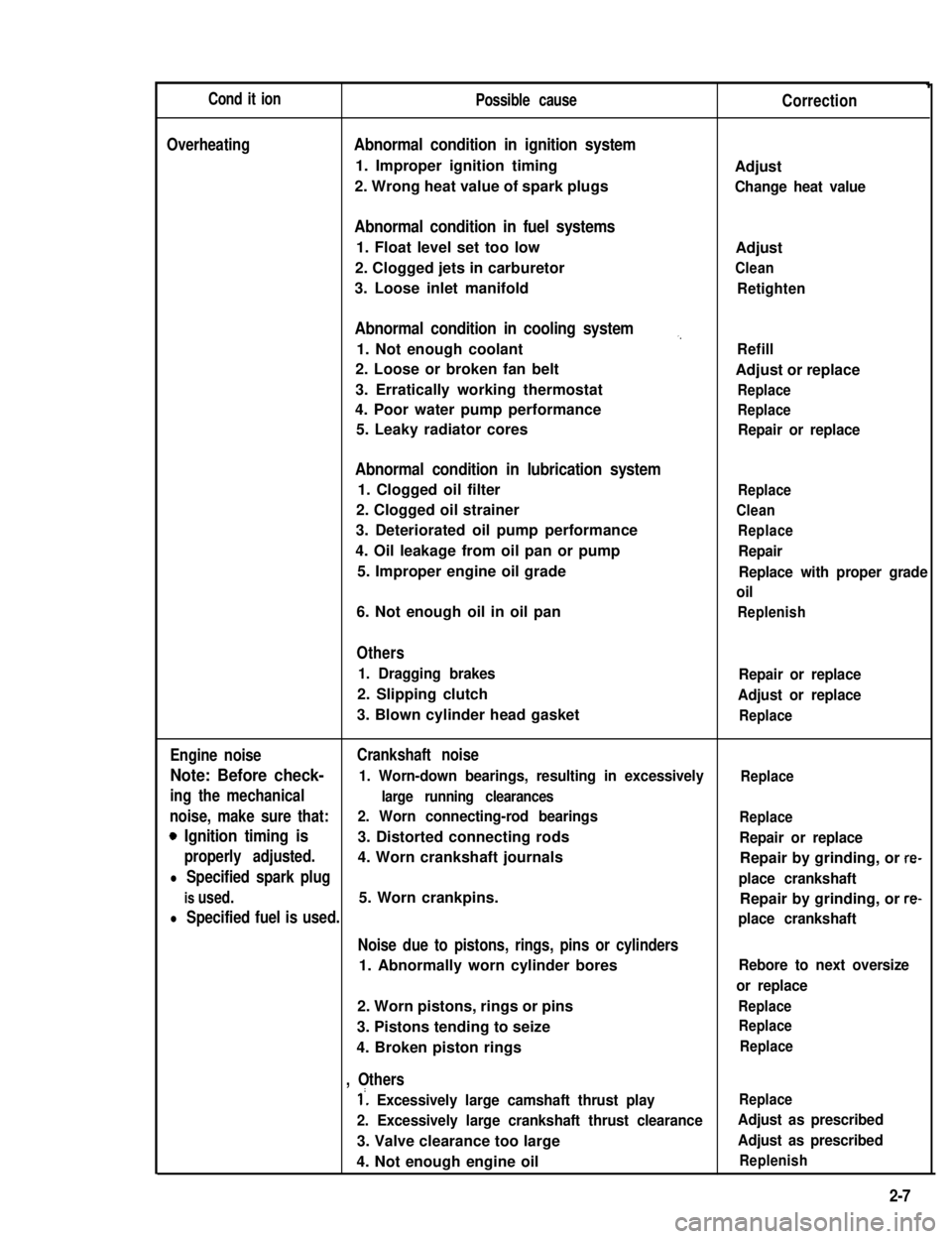
Cond it ionPossible causeCorrection
OverheatingAbnormal condition in ignition system
1. Improper ignition timingAdjust
2. Wrong heat value of spark plugsChange heat value
Abnormal condition in fuel systems
1. Float level set too lowAdjust
2. Clogged jets in carburetorClean
3. Loose inlet manifoldRetighten
Abnormal condition in cooling system,,
1. Not enough coolantRefill
2. Loose or broken fan beltAdjust or replace
3. Erratically working thermostatReplace
4. Poor water pump performanceReplace
5. Leaky radiator coresRepair or replace
Abnormal condition in lubrication system
1. Clogged oil filterReplace
2. Clogged oil strainerClean
3. Deteriorated oil pump performanceReplace
4. Oil leakage from oil pan or pumpRepair
5. Improper engine oil gradeReplace with proper grade
oil
6. Not enough oil in oil panReplenish
Others
1. Dragging brakesRepair or replace
2. Slipping clutchAdjust or replace
3. Blown cylinder head gasketReplace
Engine noiseCrankshaft noise
Note: Before check- 1. Worn-down bearings, resulting in excessivelyReplace
ing the mechanicallarge running clearances
noise, make sure that:2. Worn connecting-rod bearingsReplace
0 Ignition timing is3. Distorted connecting rodsRepair or replace
properly adjusted.4. Worn crankshaft journalsRepair by grinding, or re-
l Specified spark plugplace crankshaft
is used.5. Worn crankpins.Repair by grinding, or re-
l Specified fuel is used.place crankshaft
Noise due to pistons, rings, pins or cylinders
1. Abnormally worn cylinder boresRebore to next oversize
or replace
2. Worn pistons, rings or pinsReplace
3. Pistons tending to seizeReplace
4. Broken piston ringsReplace
, Others
1’. Excessively large camshaft thrust playReplace
2. Excessively large crankshaft thrust clearanceAdjust as prescribed
3. Valve clearance too largeAdjust as prescribed
4. Not enough engine oilReplenish
2-7
Page 46 of 962

ConditionPossible causeCorrection
High fuel consumptionAbnormal condition ignition system
1. Improper ignition timingAdjust
2. Leak or loose connection of high tension cordRepair or replace
3. Defective spark plug (improper gap, heavyClean, adjust or replace
deposits, and burned electrodes, etc..)
4. Cracked distributor cap or rotorReplace
5. Malfunctioning mechanical and vacuumCheck and repair or
advancers in distributorreplace
Abnormal condition in fuel system
1. Improper float levelAdjust
2. Fuel leakage from tank, pipe or carburetorRepair or replace
3. Malfunctioning carburetor choke systemRepair or replace
4. Dirty or clogged carburetor jetsClean
5. Clogged air cleaner elementClean or replace
6. Malfunctioning thermostatically controlledCheck and repair or
air cleanerreplace
Abnormal condition in engine
1. Low compressionPreviously outlined
2. Poor valve seatingRepair or replace
3. Improper valve clearanceAdjust
Emission control
1. Air leaks at exhaust manifoldTighten manifold bolts
and nuts.
Replace gasket.
2. Oxygen sensor out of orderReplace.
3. Water temperature switch out of orderReplace.
4. Malfunctioning throttle position switchReplace
5. Malfunctioning MCS (mixture controlReplace
solenoid) valve in carburetor
6. Malfunctioning EGR valveReplace
Others
1. Dragging brakesRepair or replace
2. Slipping clutchAdjust or replace
3. Improper tire pressureAdjust
Excessive engine oilOil leakage
consumption1. Loose oil drain plugTighten
2. Loose oil pan securing boltsTighten
3. Deteriorated or broken oil pan sealantReplace sealant
4. Leaky oil sealsReplace
5. Blown cylinder head gasketReplace
6. Improper tightening of oil filterTighten
7. Loose oil pressure switchTighten
2-8
Page 55 of 962
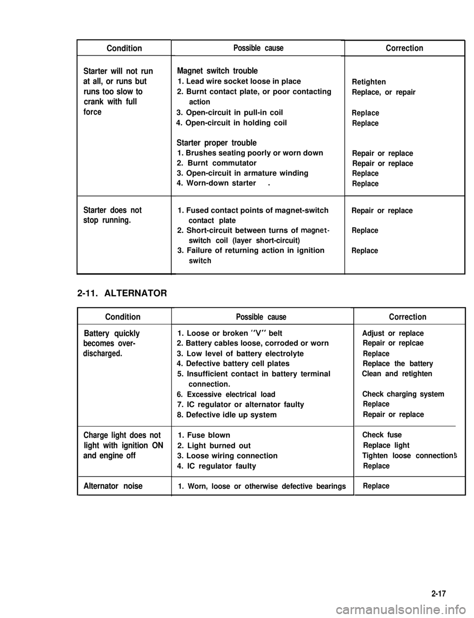
Condition
Starter will not run
at all, or runs but
runs too slow to
crank with full
force
Starter does not
stop running.
2-11. ALTERNATOR
Condition
Battery quickly
becomes over-
discharged.
Charge light does not
light with ignition ON
and engine off
Alternator noise
Possible cause
Magnet switch trouble
1. Lead wire socket loose in place
2. Burnt contact plate, or poor contacting
action
3. Open-circuit in pull-in coil
4. Open-circuit in holding coil
Starter proper trouble
1. Brushes seating poorly or worn down
2. Burnt commutator
3. Open-circuit in armature winding
4. Worn-down starter.
1. Fused contact points of magnet-switch
contact plate
2. Short-circuit between turns of magnet-
switch coil (layer short-circuit)
3. Failure of returning action in ignition
switch
Possible cause
1. Loose or broken “V” belt
2. Battery cables loose, corroded or worn
3. Low level of battery electrolyte
4. Defective battery cell plates
5. Insufficient contact in battery terminal
connection.
6. Excessive electrical load
7. IC regulator or alternator faulty
8. Defective idle up system
1. Fuse blown
2. Light burned out
3. Loose wiring connection
4. IC regulator faulty
1. Worn, loose or otherwise defective bearings
Correction
Retighten
Replace, or repair
Replace
Replace
Repair or replace
Repair or replace
Replace
Replace
Repair or replace
Replace
Replace
Correction
Adjust or replace
Repair or replcae
Replace
Replace the battery
Clean and retighten
Check charging system
Replace
Repair or replace
Check fuse
Replace light
Tighten loose connection!
Replace
i
Replace
2-17
Page 65 of 962
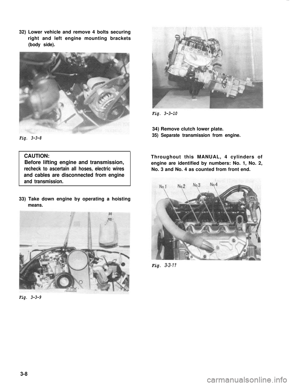
32) Lower vehicle and remove 4 bolts securing
right and left engine mounting brackets(body side).
Fig. 3-3-10
Fig. 3-3-8
CAUTION:Before lifting engine and transmission,
recheck to ascertain all hoses, electric wires
and cables are disconnected from engine
and transmission.
34) Remove clutch lower plate.
35) Separate transmission from engine.
Throughout this MANUAL, 4 cylinders ofengine are identified by numbers: No. 1, No. 2, No. 3 and No. 4 as counted from front end.
33) Take down engine by operating a hoisting
means.
Fig. 3-3-11
Fig. 3-3-9
3-8
Page 74 of 962
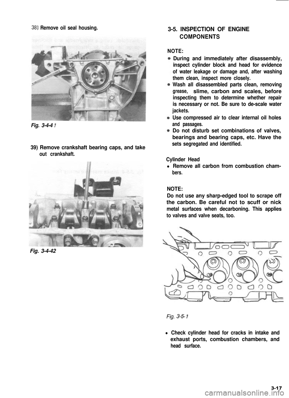
38) Remove oil seal housing.
Fig. 3-4-4 1
39) Remove crankshaft bearing caps, and take
out crankshaft.
Fig. 3-4-42
3-5. INSPECTION OF ENGINE
COMPONENTS
NOTE:
During and immediately after disassembly,
inspect cylinder block and head for evidence
of water leakage or damage and, after washing
them clean, inspect more closely.
Wash all disassembled parts clean, removing
grease,slime, carbon and scales, before
inspecting them to determine whether repair
is necessary or not. Be sure to de-scale water
jackets.
Use compressed air to clear internal oil holes
and passages.
Do not disturb set combinations of valves,
bearings and bearing caps, etc. Have the
sets segregated and identified.
Cylinder Head
l Remove all carbon from combustion cham-
bers.
NOTE:
Do not use any sharp-edged tool to scrape off
the carbon. Be careful not to scuff or nick
metal surfaces when decarboning. This applies
to valves and valve seats, too.
Fig. 3-5 1
l Check cylinder head for cracks in intake and
exhaust ports, combustion chambers, and
head surface.
3-17
Page 92 of 962
3-6. ENGINE REASSEMBLY
NOTE:
l All parts to be used in reassembly must be
perfectly clean.
l Oil sliding and rubbing surfaces of engine
parts just before using them in reassembly.
Use engine oil (Refer to page l-8).
l Have liquid packing ready for use. SUZUKI
BOND NO. 1215 is specified for it. Use it
wherever its use is specified in order to
ensure leak-free (oil and water) workmanship
of reassembly.
l There are many running clearances. During
the course of engine reassembly, be sure to
check these clearances, one after another,
as they form.
l Gaskets, “0” rings and similar sealing mem-
bers must be in perfect condition. For these
members, use replacement parts in stock.
l Tightening torque is specified for impor-
tant fasteners - mainly bolts and nuts -of
the engine and other components. Use torque
wrenches and constantly refer to the specified
values given on p. 3-58.
l Do not disregard match marks provided on
parts. Some of them are those given at the
time of disassembly.
l There are many sets of parts. Crankshaft
bearings, connecting rods, pistons, etc., are
in combination sets. Do not disturb such
combinations and make sure that each part
goes back to where it came from.
Engine reassembly is the reverse of engine disas-
sembly as far as sequence is concerned, but
there are many reassembling steps that involve
measures necessary for restoring engine as close
to factory-assembled condition as possible. Only
those steps will be dealt with here.
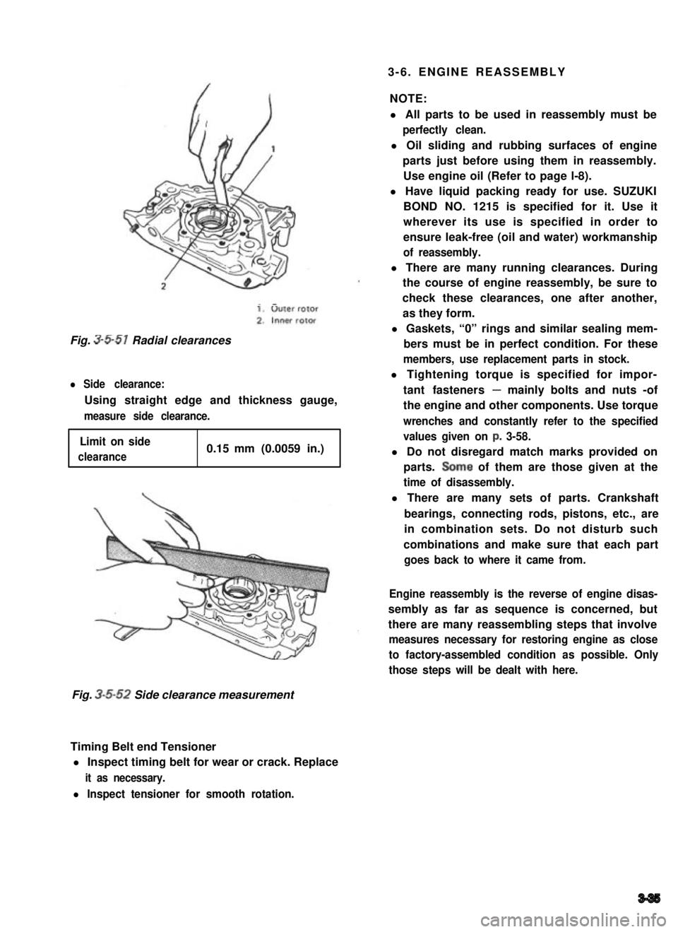
Fig. 3-5-51 Radial clearances
l Side clearance:
Using straight edge and thickness gauge,
measure side clearance.
Limit on side
clearance0.15 mm (0.0059 in.)
Fig. 3-5-52 Side clearance measurement
Timing Belt end Tensioner
l Inspect timing belt for wear or crack. Replace
it as necessary.
l Inspect tensioner for smooth rotation.
3-35
Page 94 of 962
n
U
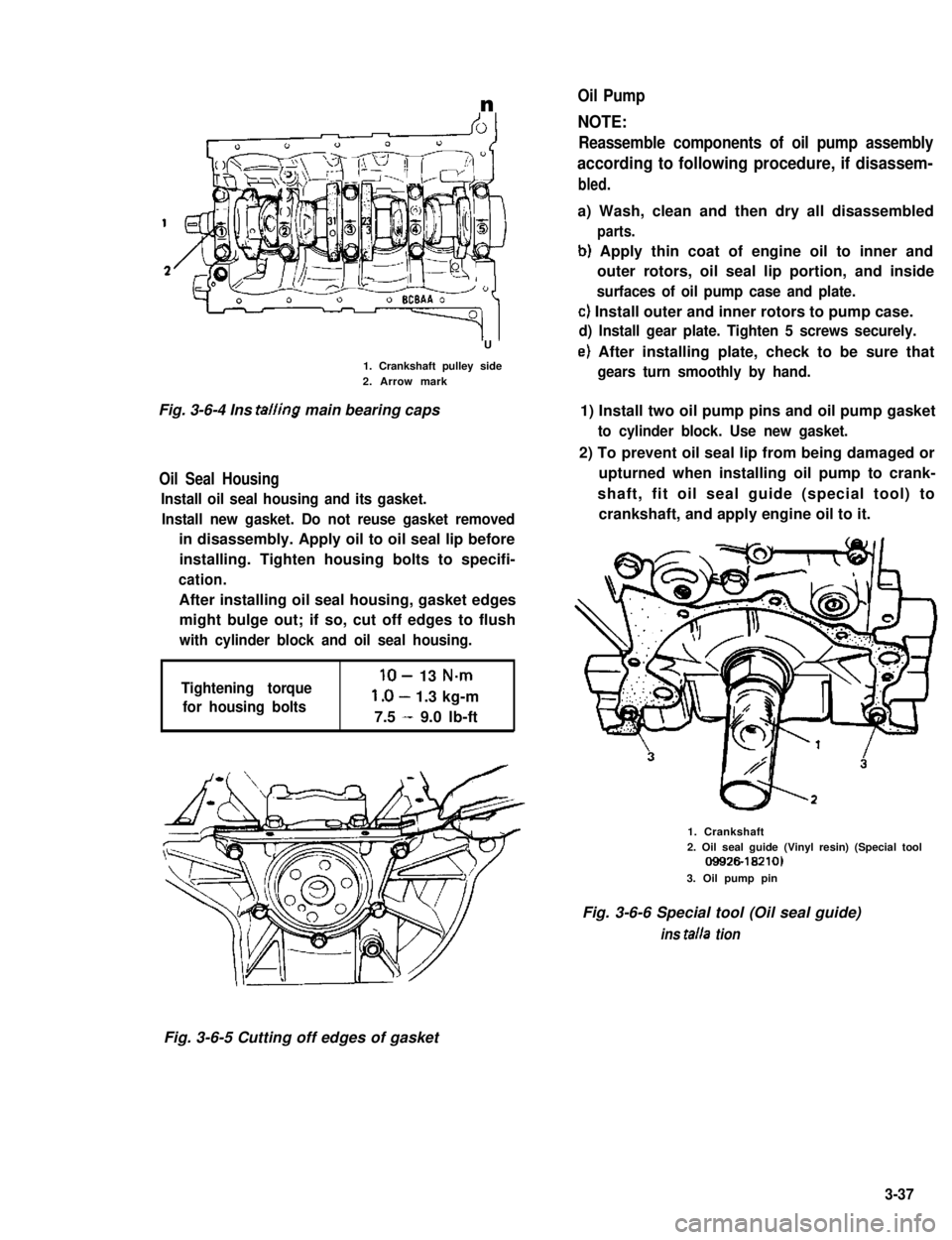
1. Crankshaft pulley side2. Arrow mark
Fig. 3-6-4 Ins tailing main bearing caps
Oil Seal Housing
Install oil seal housing and its gasket.
Install new gasket. Do not reuse gasket removed
in disassembly. Apply oil to oil seal lip before
installing. Tighten housing bolts to specifi-
cation.
After installing oil seal housing, gasket edges
might bulge out; if so, cut off edges to flush
with cylinder block and oil seal housing.
Tightening torque
for housing bolts
lo- 13 N-m
l.O- 1.3 kg-m
7.5 - 9.0 lb-ft
Oil Pump
NOTE:
Reassemble components of oil pump assembly
according to following procedure, if disassem-
bled.
a) Wash, clean and then dry all disassembled
parts.
b) Apply thin coat of engine oil to inner and
outer rotors, oil seal lip portion, and inside
surfaces of oil pump case and plate.
c) Install outer and inner rotors to pump case.
d) Install gear plate. Tighten 5 screws securely.
e) After installing plate, check to be sure that
gears turn smoothly by hand.
1) Install two oil pump pins and oil pump gasket
to cylinder block. Use new gasket.
2) To prevent oil seal lip from being damaged or
upturned when installing oil pump to crank-
shaft, fit oil seal guide (special tool) to
crankshaft, and apply engine oil to it.
1. Crankshaft2. Oil seal guide (Vinyl resin) (Special tool09926-18210)
3. Oil pump pin
Fig. 3-6-6 Special tool (Oil seal guide)
ins talla tion
Fig. 3-6-5 Cutting off edges of gasket
3-37
Page 101 of 962
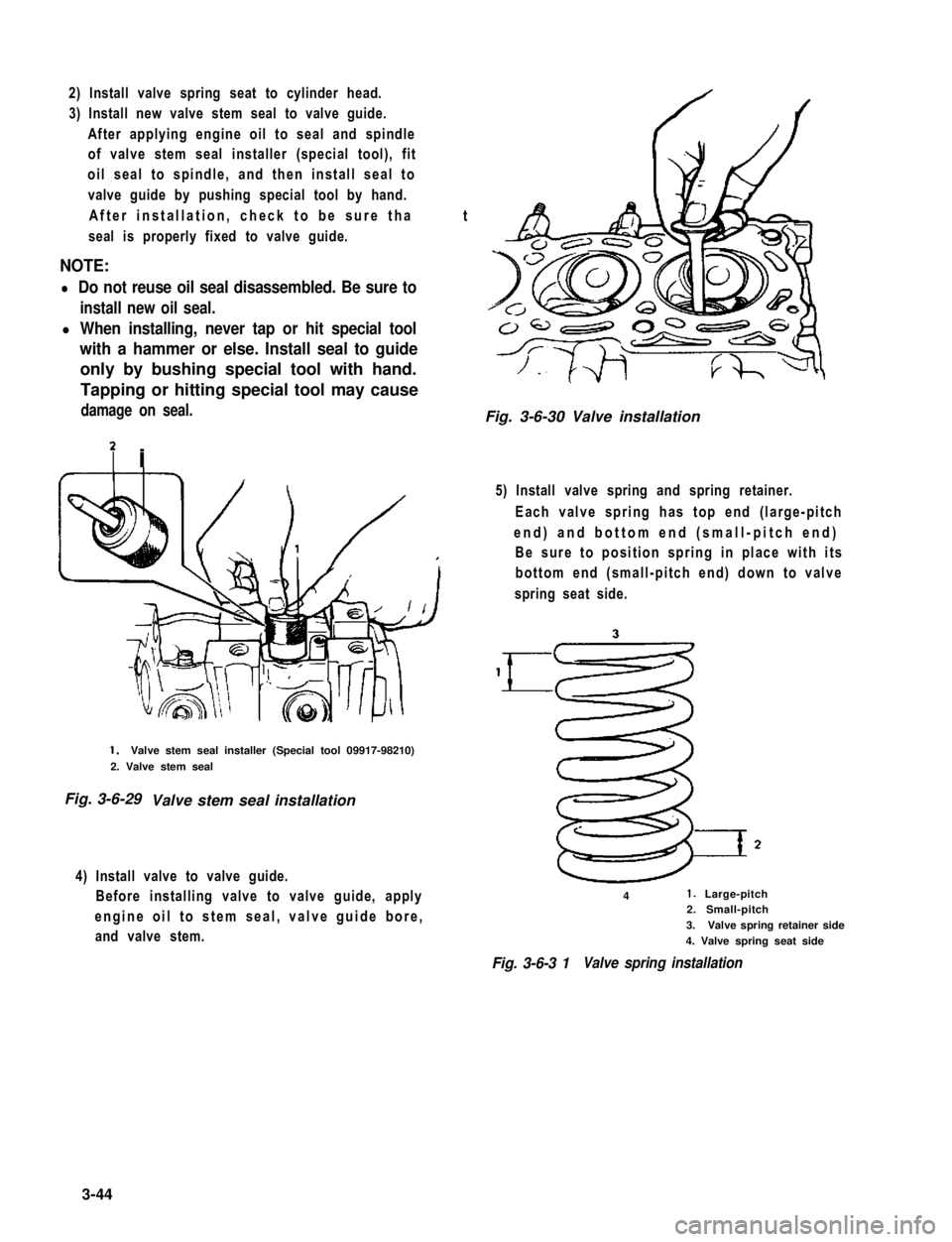
2) Install valve spring seat to cylinder head.
3) Install new valve stem seal to valve guide.
After applying engine oil to seal and spindle
of valve stem seal installer (special tool), fit
oil seal to spindle, and then install seal to
valve guide by pushing special tool by hand.
After installation, check to be sure that
seal is properly fixed to valve guide.
NOTE:
l Do not reuse oil seal disassembled. Be sure to
install new oil seal.
l When installing, never tap or hit special tool
with a hammer or else. Install seal to guide
only by bushing special tool with hand.
Tapping or hitting special tool may cause
damage on seal.
7 i
1.Valve stem seal installer (Special tool 09917-98210)
2. Valve stem seal
Fig. 3-6-29 Valve stem seal installation
4) Install valve to valve guide.
Before installing valve to valve guide, apply
engine oil to stem seal, valve guide bore,
and valve stem.
Fig. 3-6-30 Valve installation
5) Install valve spring and spring retainer.
Each valve spring has top end (large-pitch
end) and bottom end (small-pitch end)
Be sure to position spring in place with its
bottom end (small-pitch end) down to valve
spring seat side.
41. Large-pitch2. Small-pitch
3.Valve spring retainer side
4. Valve spring seat side
Fig. 3-6-3 1Valve spring installation
3-44