1987 SUZUKI GRAND VITARA check engine
[x] Cancel search: check enginePage 143 of 962

3) Reinstall carburetor following normal service
procedures.
Connect emission control system hoses and
lead wires. Make specified play on accelerator
cable and refill cooling system.
4) Place transaxle gear shift lever in “Neutral”,
set parking brake and block drive wheels.
5) Start engine, and warm it up to normal
operating temperature, stop engine.
6) Be sure to check the following before idle
mixture adjustment.
l Fuel level is within round mark at the
center of level gauge.
l Valve lash is checked and adjusted accord-
ing to the maintenance schedule.
l Air cleaner has been properly installed
and is in good condition.
l All accessories (wipers, heater, lights etc)
are out of service.
l Ignition timing is within specification.
l Choke valve opens fully.
l Idle-up actuator does not operate.
7) Check and adjust idle speed to specification
if necessary.
8) Remove seal rubber of duty check coupler
and connect positive terminal of duty
meter to“Blue/Red” wire and negative
terminal to “Black/Green” wire.
9) Run engine at 1,500 - 2,000 r/min for 30
seconds and bring it to idle speed.
10) With engine running at idle speed, adjust idle
mixture adjusting screw slowly in small incre-
ment allowing time for duty to stabilize after
turning screw to obtain duty of 10 - 50.
If duty is too low, back screw out; if too
high, screw it in. After obtaining duty of
10 - 50, recheck idle speed, and adjust if
necessary.
NOTE:
If adjustment can’t be made because duty meter
indicator does not deflect, check feed back
system according to the checking procedure of
system described in section of Emission Control
System.
11) After adjustment, install seal rubber to duty
check coupler and drive in idle mixture
adjusting screw pin.
4-28
Page 144 of 962
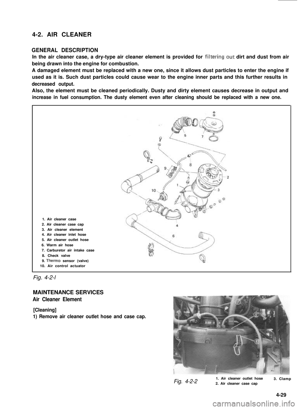
4-2. AIR CLEANER
GENERAL DESCRIPTION
In the air cleaner case, a dry-type air cleaner element is provided for filtering.out dirt and dust from air
being drawn into the engine for combustion.
A damaged element must be replaced with a new one, since it allows dust particles to enter the engine if
used as it is. Such dust particles could cause wear to the engine inner parts and this further results in
decreased output.
Also, the element must be cleaned periodically. Dusty and dirty element causes decrease in output and
increase in fuel consumption. The dusty element even after cleaning should be replaced with a new one.
Fig. 4-2-l
1. Air cleaner case
2. Air cleaner case cap
3. Air cleaner element4. Air cleaner inlet hose
5. Air cleaner outlet hose
6. Warm air hose
7. Carburetor air intake case
8. Check valve
9. Therm0 sensor (valve)10. Air control actuator
MAINTENANCE SERVICES
Air Cleaner Element
[Cleaning]
1) Remove air cleaner outlet hose and case cap.
Fig. 4-2-21. Air cleaner outlet hose2. Air cleaner case cap3. Clamp
4-29
Page 149 of 962
![SUZUKI GRAND VITARA 1987 Service Repair Manual ,Fuel Pump
[ Rem’oval]
1) Disconnect negative cable from battery.
2) Remove fuel filler cap from fuel filler neck to
release fuel vapor pressure in fuel tank. After
releasing, reinstall the cap.
3) SUZUKI GRAND VITARA 1987 Service Repair Manual ,Fuel Pump
[ Rem’oval]
1) Disconnect negative cable from battery.
2) Remove fuel filler cap from fuel filler neck to
release fuel vapor pressure in fuel tank. After
releasing, reinstall the cap.
3)](/manual-img/20/57437/w960_57437-148.png)
,Fuel Pump
[ Rem’oval]
1) Disconnect negative cable from battery.
2) Remove fuel filler cap from fuel filler neck to
release fuel vapor pressure in fuel tank. After
releasing, reinstall the cap.
3) Disconnect fuel inlet, outlet and return hoses
from fuel pump.
Fuel Filter
[Removal]
1) Disconnect negative cable from battery.
2) Remove fuel filler cap to release fuel vapor
pressure in fuel tank. After releasing, reinstall
the cap.
3) Disconnect inlet and outlet hoses from fuel
filter.
4) Remove fuel filter with clamp.
[Installation]
1) Install filter and clamp, and connect inlet
and outlet hoses to fuel filter.
NOTE:.
The top connection is for outlet hose, the
lower one for inlet hose.
1. Fuel pump
2. Inlet hose3. Outlet hose
4. Return hose
Fig. 4-2-l 1
4) Remove fuel pump from cylinder head.
5) Remove fuel pump rod from cylinder head.
2
1. Fuel pump rod
2. Cylinder head
[Installation]
Reverse removal procedure for installation
using care for the following.
l After oiling it,install fuel pump rod to
cylinder head.
0 Use new fuel pump gasket.
l Make sure for proper hose connection.
0 Upon completion of installation, start engine
and check fuel hose or its joints for leaks.
1.Fuel filter3.From fueltank
2.To fuel pump4.Clamp
Fig.4-2-13
2) Connect negative cable to battery.
3) After installation, start engine and check it
for leaks.
Fuel Tank
[Removal]
1) Disconnect negative cable from battery.
2) Disconnect fuel level gauge lead wire.
3) To release the pressure in fuel tank, remove
fuel filler cap and then, reinstall it.
4) Raise car on hoist.
5) Drain fuel by removing drain plug.
6) Remove filler hose protector.
7) Disconnect filler hose from fuel tank.
.8) Disconnect fuel hosesand pipe from fuel tank.
9) Remove fuel tank.
4-34
Page 150 of 962
![SUZUKI GRAND VITARA 1987 Service Repair Manual [Fuel tank purging procedure]
WARNING:
This purging procedure will NOT remove
all fuel vapor. Do not attempt any repair
on tank where heat or flame is required, as
an explosion resulting in personal i SUZUKI GRAND VITARA 1987 Service Repair Manual [Fuel tank purging procedure]
WARNING:
This purging procedure will NOT remove
all fuel vapor. Do not attempt any repair
on tank where heat or flame is required, as
an explosion resulting in personal i](/manual-img/20/57437/w960_57437-149.png)
[Fuel tank purging procedure]
WARNING:
This purging procedure will NOT remove
all fuel vapor. Do not attempt any repair
on tank where heat or flame is required, as
an explosion resulting in personal injury
cou Id occur.J
The following procedure is used for purging the
fuel tank.
1) After removing fuel tank, remove all hoses,
fuel level gauge from fuel tank.
2) Drain all remaining fuel from tank.
3) Move tank to flushing area.
4) Fill tank with warm water or tap water, and
agitate vigorously and drain. Repeat this
washing until inside of tank is clean.
Replace tank if inside is rusty.
5) Completely flush out remaining water after
washing.
[ Installation]
Reverse removal procedure for installation using
care for the following.
Tightening torque30-45 Nm
for fuel tank(3.0- 4.5 kg-m)
drain plug(22.0 - 32.5 lb-ft)
Refer to Fig. 4-2-5 for piping and clamp posi-
tions.
l Make sure for correct hose-to-pipe connec-
tion.
l Clamp hoses securely.
l Upon completion of installation, start engine
and check hose joints for leaks.
MAINTENANCE SERVICES
Fuel Lines
Visually inspect fuel lines and connections for
evidence of fuel leakage, hose cracking, and
damage. Make sure all clamps are secure.
Repair leaky joints, if any.
Replace hoses that are suspected of being crack-
ed.
Fig. 4-2-14
Fuel Filler (tank) Cap
Visually inspect gasket of fuel filler cap.
If it is damaged or deteriorated, replace filler cap
with new one.
NOTE:
If cap requires replacement, only a cap with
the same features should be used. Failure to
use correct cap can result in a serious malfunc-
tion of the system.
Fig. 4-2-15
1. Fuel filler cap
2. Fuel filler capgasket
Fuel Filter
As said before, this filter does not permit dis-
assembly: it is to be replaced with a new one
periodically.
Replace fuel filter referring to previous item of
“Fuel Filter Removal and Installation”.
This servicing must be performed in a well
ventilated area and away from any open
flames (such as gas hot water heaters).
4-35
Page 155 of 962
5-l. GENERAL DESCRIPTION
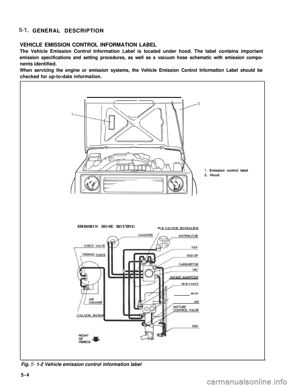
VEHICLE EMISSION CONTROL INFORMATION LABEL
The Vehicle Emission Control Information Label is located under hood. The label contains important
emission specifications and setting procedures, as well as a vacuum hose schematic with emission compo-
nents identified.
When servicing the engine or emission systems, the Vehicle Emission Control Information Label should be
checked for up-to-date information. 1.
Emission control label
2. Hood
EMISSION HOSE ROUTING EGR VACUUM MODULATOR
THERM0 VALVE
\/-
I I
EGR-VALVE-/------
BVSV
Rr,JET
/VACUUM MOTOR
Fig.
5- 1-2 Vehicle emission control information label
5- 4
Page 157 of 962
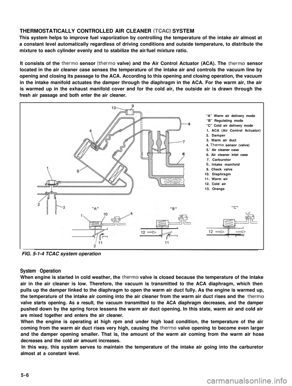
THERMOSTATICALLY CONTROLLED AIR CLEANER (TCAC) SYSTEM
This system helps to improve fuel vaporization by controlling the temperature of the intake air almost at
a constant level automatically regardless of driving conditions and outside temperature, to distribute the
mixture to each cylinder evenly and to stabilize the air/fuel mixture ratio.
It consists of the therm0 sensor (therm0 valve) and the Air Control Actuator (ACA). The therm0 sensor
located in the air cleaner case senses the temperature of the intake air and controls the vacuum line by
opening and closing its passage to the ACA. According to this opening and closing operation, the vacuum
in the intake manifold actuates the damper through the diaphragm in the ACA. For the warm air, the air
is warmed up in the exhaust manifold cover and for the cold air, the outside air is drawn through the
fresh air passage and both enter the air cleaner.
“A” Warm air delivery mode
6“B” Regulating mode
“C” Cold air delivery mode
1. ACA (Air Control Actuator)
2. Damper3. Warm air duct
4. Therm0 sensor (valve)5.’ Air cleaner case66. Air cleaner inlet case
7. Carburetor8. Intake manifold9. Check valve10. Diaphragm11. Warm air
12. Cold air
13. Orange
--
System Operation
When engine is started in cold weather, the therm0 valve is closed because the temperature of the intake
air in the air cleaner is low. Therefore, the vacuum is transmitted to the ACA diaphragm, which then
pulls up the damper linked to the diaphragm to open the warm air duct fully. As the engine is warmed up,
the temperature of the intake air coming into the air cleaner from the warm air duct rises and the therm0
valve starts opening. As a result, the vacuum transmitted to the ACA diaphragm decreases, and the damper
pushed down by the spring force lessens the warm air duct opening. In this state, warm air and cold air
are mixed together and enters the air cleaner.
When the engine is operating at high rpm and under high load condition, the temperature of the air
coming from the warm air duct rises very high, causing the therm0 valve opening to become even larger
and the damper opening smaller. That is, the amount of the warm air coming from the warm air hose
decreases and the cold air amount increases.
In this way, this system serves to maintain the temperature of the intake air going into the carburetor
almost at a constant level.
5-6
FIG. 5-1-4 TCAC system operation
Page 167 of 962
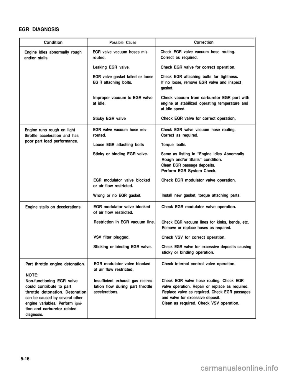
EGR DIAGNOSIS
Condition
Engine idles abnormally rough
and/or stalls.
Possible CauseCorrection
EGR valve vacuum hoses mis-Check EGR valve vacuum hose routing.
routed.Correct as required.
Leaking EGR valve.Check EGR valve for correct operation.
EGR valve gasket failed or looseCheck EGR attaching bolts for tightness.
EG R attaching bolts.If no loose, remove EGR valve and inspect
gasket.
Improper vacuum to EGR valveCheck vacuum from carburetor EGR port with
at idle.engine at stabilized operating temperature and
at idle speed.
Engine runs rough on light
throttle acceleration and has
poor part load performance.
Sticky EGR valve
EGR valve vacuum hose mis-
routed.
Loose EGR attaching bolts
Sticky or binding EGR valve.
Check EGR valve for correct operation,
Check EGR valve vacuum hose routing.
Correct as required.
Torque bolts.
Same as listing in “Engine idles Abnomrally
Rough and/or Stalls” condition.
Clean EGR passage deposits.
Perform EGR System Check.
EGR modulator valve blocked
or air flow restricted.
Check EGR modulator valve operation.
Engine stalls on decelerations.
Wrong or no EGR gasket.
EGR modulator valve blocked
of air flow restricted.
Install new gasket, torque attaching parts.
Check EGR modulator valve operation.
Restriction in EGR vacuum line.Check EGR vacuum lines for kinks, bends, etc.
Remove or replace hoses as required.
VSV filter plugged.
Sticking or binding EGR valve.
Check VSV for correct operation.
Check EGR valve for excessive deposits causing
sticky or binding operation.
Part throttle engine detonation.EGR modulator valve blockedCheck internal control valve operation.
of air flow restricted.
NOTE:
Non-functioning EGR valveInsufficient exhaust gas recircu-Check EGR valve hose routing. Check EGR
could contribute to partlation flow during part throttlevalve operation. Repair or replace as required.
throttle detonation. Detonationaccelerations.Replace valve as required. Check EGR passages
can be caused by several otherand valve for excessive deposit.
engine variables. Perform igni-Clean as required. Check VSV operation.
tion and carburetor related
diagnosis.
5-16
Page 168 of 962
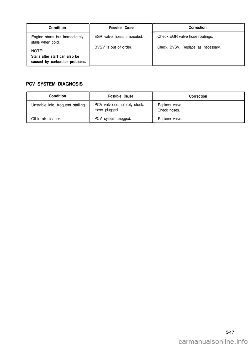
Condition
Engine starts but immediately
stalls when cold.
NOTE:
Stalls after start can also be
caused by carburetor problems.
PCV SYSTEM DIAGNOSIS
Condition
Unstable idle, frequent stalling.
Oil in air cleaner.
Possible Cause
EGR valve hoses misrouted.
BVSV is out of order.
Possible Cause
PCV valve completely stuck.
Hose plugged.
PCV system plugged.
Correction
Check EGR valve hose routings.
Check BVSV. Replace as necessary.
Correction
Replace valve.
Check hoses.
Replace valve.
5-17