1987 SUZUKI GRAND VITARA check engine
[x] Cancel search: check enginePage 169 of 962
5-3. MAINTENANCE SERVICE
GENERAL
If the emission control hoses were disconnected
and any system component was removed for
service,be sure to reinstall the component
properly and route and connect hoses correctly
after service. Refer to Fig. 5-l-l for hose con-
nection.
PCV SYSTEM
Checking PCV System
NOTE:
If the engine is idling rough, this may be caused
by a stuck PCV valve, plugged hoses or vacuum
leakage of PCV line, therefore, never adjust the
carburetor idle without first checking the PCV
valve and hoses.
[ PCV hoses]
Check hoses for connection, leakage, clog, and
deterioration. Replace as necessary.
[ PCV valve]
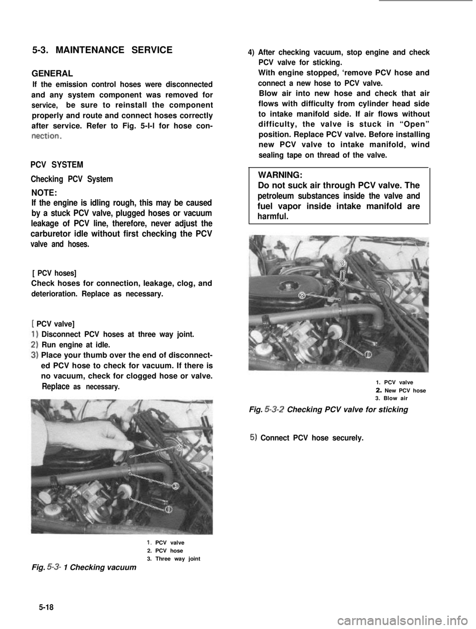
Disconnect PCV hoses at three way joint.
Run engine at idle.
Place your thumb over the end of disconnect-
ed PCV hose to check for vacuum. If there is
no vacuum, check for clogged hose or valve.
Replace as necessary.
4) After checking vacuum, stop engine and check
PCV valve for sticking.
With engine stopped, ‘remove PCV hose and
connect a new hose to PCV valve.
Blow air into new hose and check that air
flows with difficulty from cylinder head side
to intake manifold side. If air flows without
difficulty, the valve is stuck in “Open”
position. Replace PCV valve. Before installing
new PCV valve to intake manifold, wind
sealing tape on thread of the valve.
WARNING:
Do not suck air through PCV valve. The
petroleum substances inside the valve and
fuel vapor inside intake manifold are
harmful.
1. PCV valve
2. New PCV hose3. Blow air
Fig. 5-3-2 Checking PCV valve for sticking
5) Connect PCV hose securely.
1. PCV valve
2. PCV hose
3. Three way joint
Fig. 5-3- 1 Checking vacuum
5-18
Page 170 of 962
TCAC SYSTEM
Checking TCAC System
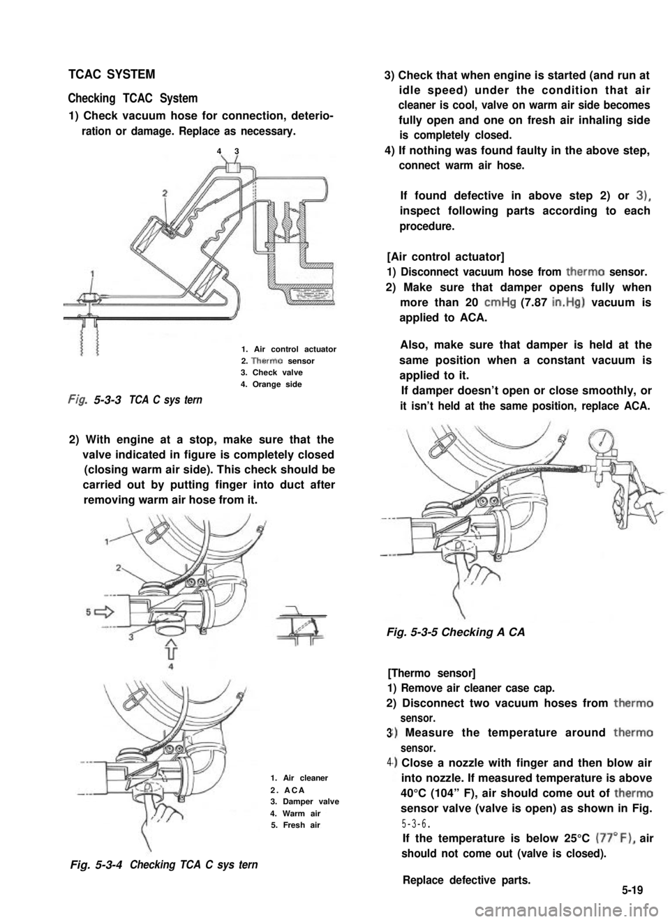
1) Check vacuum hose for connection, deterio-
ration or damage. Replace as necessary.
4 3
3) Check that when engine is started (and run at
idle speed) under the condition that air
cleaner is cool, valve on warm air side becomes
fully open and one on fresh air inhaling side
is completely closed.
4) If nothing was found faulty in the above step,
connect warm air hose.
1. Air control actuator
2. Therm0 sensor3. Check valve
4. Orange side
Fig, 5-3-3TCA C sys tern
2) With engine at a stop, make sure that the
valve indicated in figure is completely closed
(closing warm air side). This check should be
carried out by putting finger into duct after
removing warm air hose from it.
Fig. 5-3-4Checking TCA C sys tern
If found defective in above step 2) or 3),
inspect following parts according to each
procedure.
[Air control actuator]
1) Disconnect vacuum hose from therm0 sensor.
2) Make sure that damper opens fully when
more than 20 cmHg (7.87 in.Hg) vacuum is
applied to ACA.
Also, make sure that damper is held at the
same position when a constant vacuum is
applied to it.
If damper doesn’t open or close smoothly, or
it isn’t held at the same position, replace ACA.
Fig. 5-3-5 Checking A CA
3
4
1. Air cleaner
2. ACA3. Damper valve
4. Warm air5. Fresh air
[Thermo sensor]
1) Remove air cleaner case cap.
2) Disconnect two vacuum hoses from therm0
sensor.
I) Measure the temperature around therm0
sensor.
.) Close a nozzle with finger and then blow air
into nozzle. If measured temperature is above
40°C (104” F), air should come out of therm0
sensor valve (valve is open) as shown in Fig.
5-3-6.
If the temperature is below 25°C (77”F), air
should not come out (valve is closed).
Replace defective parts.5-19
Page 172 of 962
![SUZUKI GRAND VITARA 1987 Service Repair Manual [Hoses]
Visually inspect hoses and pipe for cracks,
damage, or excessive bends, and hose connec-
tion for tightness.
Fig. 5-3-9
HOT IDLE COMPENSATOR (HIC)
Checking Hot Idle Compensator
1) Remove air i SUZUKI GRAND VITARA 1987 Service Repair Manual [Hoses]
Visually inspect hoses and pipe for cracks,
damage, or excessive bends, and hose connec-
tion for tightness.
Fig. 5-3-9
HOT IDLE COMPENSATOR (HIC)
Checking Hot Idle Compensator
1) Remove air i](/manual-img/20/57437/w960_57437-171.png)
[Hoses]
Visually inspect hoses and pipe for cracks,
damage, or excessive bends, and hose connec-
tion for tightness.
Fig. 5-3-9
HOT IDLE COMPENSATOR (HIC)
Checking Hot Idle Compensator
1) Remove air intake case with hose.
2) Check temperature around HIC with thermo-
meter.
3) If temperature is below 45°C (113” F), air
should not come out of HIC when air is
blown into hose. If temperature is above
65°C (149” F), air comes out of HIC.
Replace H IC if defective.
4) After checking, install air intake case and
connect hose to intake manifold.
NOTE:
l To check HIC for operation at higher than
65°C (149°F) temperature when HIC (bi-
metal) temperature is lower than 45°C
(113”F), warm it up with hair drier or photo
light before checking.
l Never touch bimetal or valve in HIC.
1
Below 45°C (113’F)Above 65’C (149’F)
Fig.5-i- 10
DECELERATION MIXTURE CONTROL
SYSTEM
Checking
[Hoses]
Inspect each hose for pinholes, cracks or damage.
Also check to ensure that each joint is securely
connected. Any part found defective must be
corrected or replaced.
.
Fig. 5-3- 11
[Mixture control valve (MCV)]
1) Warm up the engine to normal operating
temperature.
2) Disconnect hose @ and reconnect it. At this
time, check that air is drawn into MCV.
NOTE:
At this time, the engine will idle rough or die,
but this is normal.
A piece of paper
If the above checks show anything wrong,
replace it.
5-21
Page 173 of 962
[Jet1
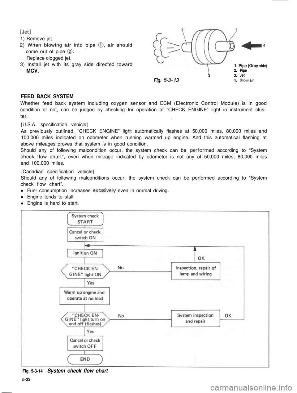
1) Remove jet.
2) When blowing air into pipe 0, air should
come out of pipe 0.
Replace clogged jet.
3) Install jet with its gray side directed toward
MCV.
1. Pipe (Gray side)2.Pipe
33.Jet
Fig.53-134.Blowair
FEED BACK SYSTEM
Whether feed back system including oxygen sensor and ECM (Electronic Control Module) is in good
condition or not, can be judged by checking for operation of “CHECK ENGINE” light in instrument clus-
ter..
[U.S.A. specification vehicle]
As previously outlined,“CHECK ENGINE” light automatically flashes at 50,000 miles, 80,000 miles and
100,000 miles indicated on odometer when running warmed up engine. And this automatical flashing at
above mileages proves that system is in good condition.
Should any of following malcondition occur, the system check can be .performed according to “System
check flow chart”,even when mileage indicated by odometer is not any of 50,000 miles, 80,000 miles
and 100,000 miles.
[Canadian specification vehicle]
Should any of following malconditions occur, the system check can be performed according to “System
check flow chart”.
l Fuel consumption increases excssively even in normal driving.
l Engine tends to stall.
l Engine is hard to start.
System check
STARTI
Cancel or check
switch ON
“CHECK EN-
Yes
Inspection, repair of
lamp and wiring1
Warm up engine and
operate at no load
I
“CHECK EN-GINE”light turnonand off (flashes)I
NoSystem inspection OK
and repair
Cancel or check
Fig. 5-3-14System check flow chart
5-22
Page 174 of 962
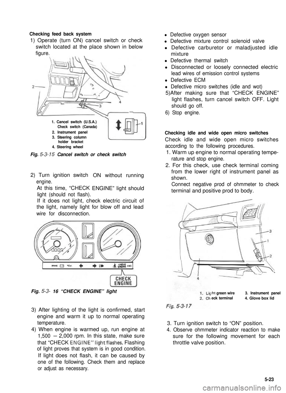
Checking feed back system
1) Operate (turn ON) cancel switch or check
l Defective oxygen sensor
l Defective mixture control solenoid valve
switch located at the place shown in belowl Defective carburetor or maladjusted idle
figure.mixture
-
1. Cancel switch (U.S.A.)Check switch (Canada)
2. Instrument panel
w
$
1
3. Steering columnholder bracket
4. Steering wheel
Fig. 5-3- 15 Cancel switch or check switch
2) Turn ignition switch
engine.
At this time, “CHECK
ON without running
ENGINE” light should
light (should not flash).
If it does not light, check electric circuit of
the light, namely light for blow off and lead
wire for disconnection.
Fig. 5-3- 16 “CHECK ENGINE” light
3) After lighting of the light is confirmed, start
engine and warm it up to normal operating
temperature.
4) When engine is warmed up, run engine at
1,500- 2,000 rpm. In this state, make sure
that “CHECK ENGINE”lightflashes. Flashing
of light proves that system is in good condition.
If light does not flash, it can be caused by
one of the following. Check them and replace
or adjust as necessary.
l Defective thermal switch
l Disconnected or loosely connected electric
lead wires of emission control systems
l Defective ECM
l Defective micro switches (idle and wot)
5)After making sure that “CHECK ENGINE”
light flashes, turn cancel switch OFF. Light
should go off.
6) Stop engine.
Checking idle and wide open micro switches
Check idle and wide open micro switches
according to the following procedures.
1. Warm up engine to normal operating tempe-
rature and stop engine.
2. For this check, use check terminal coming
from the lower right of instrument panel as
shown.
Connect negative prod of ohmmeter to check
terminal and positive prod to body.
Iht green wire
eck terminal
3. Instrument panel
4. Glove box lid
3. Turn ignition switch to “ON” position.
4. Observe ohmmeter indicator reaction to make
sure for the following movement for each
throttle valve position.
5-23
Page 177 of 962
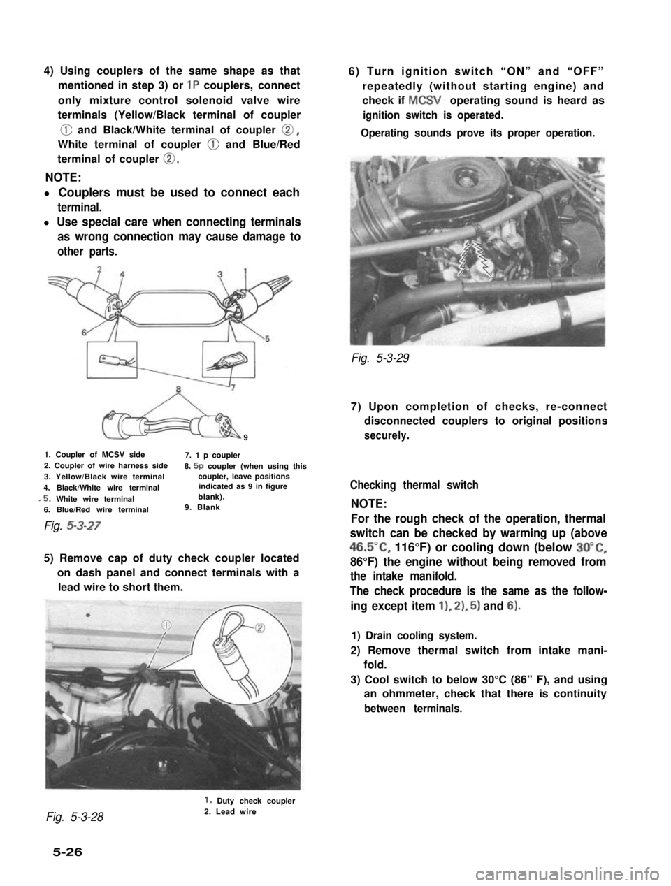
4) Using couplers of the same shape as that
mentioned in step 3) or 1P couplers, connect
only mixture control solenoid valve wire
terminals (Yellow/Black terminal of coupler
@ and Black/White terminal of coupler 0,
White terminal of coupler @ and Blue/Red
terminal of coupler 0.
NOTE:
l Couplers must be used to connect each
terminal.
l Use special care when connecting terminals
as wrong connection may cause damage to
other parts.
9
1. Coupler of MCSV side7. 1 p coupler2. Coupler of wire harness side8. 5p coupler (when using this3. Yellow/Black wire terminalcoupler, leave positions
4. Black/White wire terminalindicated as 9 in figure
,5. White wire terminalblank).
6. Blue/Red wire terminal9. Blank
Fig. 5-3-27
5) Remove cap of duty check coupler located
on dash panel and connect terminals with a
lead wire to short them.
6) Turn ignition switch “ON” and “OFF”
repeatedly (without starting engine) and
check if MCSV. operating sound is heard as
ignition switch is operated.
Operating sounds prove its proper operation.
Fig. 5-3-29
7) Upon completion of checks, re-connect
disconnected couplers to original positions
securely.
Checking thermal switch
NOTE:
For the rough check of the operation, thermal
switch can be checked by warming up (above
46.5”C, 116°F) or cooling down (below 3O”C,
86°F) the engine without being removed from
the intake manifold.
The check procedure is the same as the follow-
ing except item 11, 21, 5) and 6).
1) Drain cooling system.
2) Remove thermal switch from intake mani-
fold.
3) Cool switch to below 30°C (86” F), and using
an ohmmeter, check that there is continuity
between terminals.
Fig. 5-3-28
1. Duty check coupler2. Lead wire
5-26
Page 178 of 962
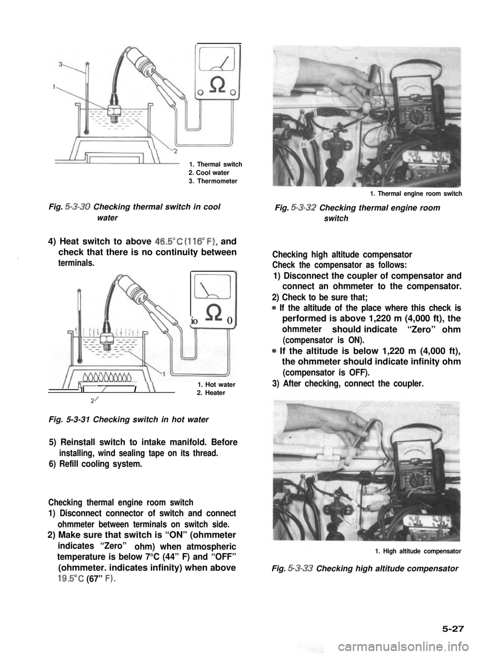
1
1. Thermal switch
2. Cool water
3. Thermometer
1. Thermal engine room switch
Fig. 5-3-30 Checking thermal switch in coolFig. 5-3-32 Checking thermal engine room
waterswitch
4) Heat switch to above 46.5”C (116”F), and
check that there is no continuity between
terminals.t
Ll
%I
Rio 0II
I \\1. Hot waterII/2. Heater
Fig. 5-3-31 Checking switch in hot water
5) Reinstall switch to intake manifold. Before
installing, wind sealing tape on its thread.
6) Refill cooling system.
Checking thermal engine room switch
1) Disconnect connector of switch and connect
ohmmeter between terminals on switch side.
2) Make sure that switch is “ON” (ohmmeter
indicates “Zero”ohm) when atmospheric
temperature is below 7°C (44” F) and “OFF”
(ohmmeter. indicates infinity) when above
19.5”C (67” F).
Checking high altitude compensator
Check the compensator as follows:
1) Disconnect the coupler of compensator and
connect an ohmmeter to the compensator.
2) Check to be sure that;
* If the altitude of the place where this check is
performed is above 1,220 m (4,000 ft), the
ohmmetershould indicate“Zero” ohm
(compensator is ON).
0 If the altitude is below 1,220 m (4,000 ft),
the ohmmeter should indicate infinity ohm
(compensator is OFF).
3) After checking, connect the coupler.
1. High altitude compensator
Fig. 5-3-33 Checking high altitude compensator
5-27
Page 179 of 962
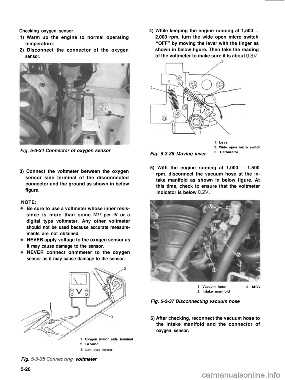
Checking oxygen sensor
1) Warm up the engine to normal operating
temperature.
2) Disconnect the connector of the oxygen
sensor.
Fig. 5-3-34 Connector of oxygen sensor
3) Connect the voltmeter between the oxygen
sensor side terminal of the disconnected
connector and the ground as shown in below
figure.
NOTE:
Be sure to use a voltmeter whose inner resis-
tance is more than some MS!Z per IV or a
digital type voltmeter. Any other voltmeter
should not be used because accurate measure-
ments are not obtained.
NEVER apply voltage to the oxygen sensor as
it may cause damage to the sensor.
NEVER connect ohmmeter to the oxygen
sensor as it may cause damage to the sensor.
i
1. Oxygen sertsor side terminal
2. Ground
3. Left side fender
4) While keeping the engine running at 1,500 -
2,000 rpm, turn the wide open micro switch
“OFF” by moving the lever with the finger as
shown in below figure. Then take the reading
of the voltmeter to make sure it is about 0.8V.
I, Lever
2. Wide open micro switch
Fig. 5-3-36 Moving lever3. Carburetor
5) With the engine running at 1,000 - 1,500
rpm, disconnect the vacuum hose at the in-
take manifold as shown in below figure. At
this time, check to ensure that the voltmeter
indicator is below 0.2V.
1. Vacuum hose
2. Intake manifold3. MCV
Fig. 5-3-37 Disconnecting vacuum hose
6) After checking, reconnect the vacuum hose to
the intake manifold and the connector of
oxygen sensor.
Fig. 5-3-35 Connec ring voltmeter
5-28