Page 185 of 962
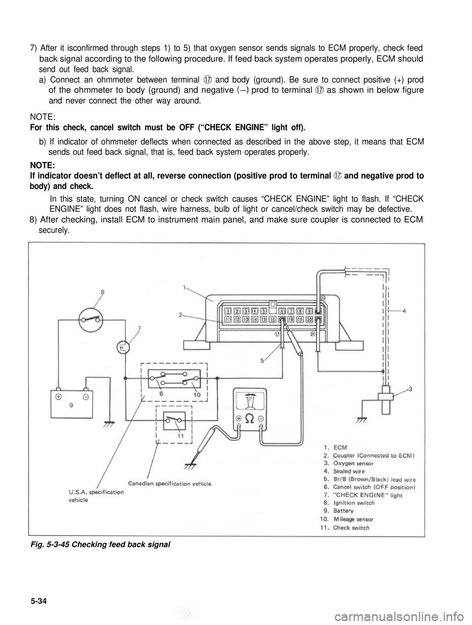
7) After it isconfirmed through steps 1) to 5) that oxygen sensor sends signals to ECM properly, check feed
back signal according to the following procedure. If feed back system operates properly, ECM should
send out feed back signal.
a) Connect an ohmmeter between terminal @I and body (ground). Be sure to connect positive (+) prod
of the ohmmeter to body (ground) and negative (-) prod to terminal @J as shown in below figure
and never connect the other way around.
NOTE:
For this check, cancel switch must be OFF (“CHECK ENGINE” light off).
b) If indicator of ohmmeter deflects when connected as described in the above step, it means that ECM
sends out feed back signal, that is, feed back system operates properly.
NOTE:
If indicator doesn’t deflect at all, reverse connection (positive prod to terminal @ and negative prod to
body) and check.
In this state, turning ON cancel or check switch causes “CHECK ENGINE” light to flash. If “CHECK
ENGINE” light does not flash, wire harness, bulb of light or cancel/check switch may be defective.
8) After checking, install ECM to instrument main panel, and make sure coupler is connected to ECM
securely.
”1,
009
7
kr
1. ECM
2. Coupler (Connected to ECM)3. Oxygen sensor4. Sealed wire
5. Br/B (Brown/Black) lead wire6. Cancel switch (OFF position)
7. “CHECK ENGINE” light
8. Ignition switch9. Battery
/
ICanadian specification vehicle
U.S.A. specificationvehicle
10. Mileage sensor
11. Check switch
Fig. 5-3-45 Checking feed back signal
5-34
Page 186 of 962
![SUZUKI GRAND VITARA 1987 Service Repair Manual [Checking idle-up signal]
The idle-up system operates when any of the small lights (such as tail light, side marker light and license
light), heater fan and rear defogger is put in operation. If the i SUZUKI GRAND VITARA 1987 Service Repair Manual [Checking idle-up signal]
The idle-up system operates when any of the small lights (such as tail light, side marker light and license
light), heater fan and rear defogger is put in operation. If the i](/manual-img/20/57437/w960_57437-185.png)
[Checking idle-up signal]
The idle-up system operates when any of the small lights (such as tail light, side marker light and license
light), heater fan and rear defogger is put in operation. If the idle-up actuator fails to operate even when
any of such equipments is put in operation, check if signal is sent to the ECM according to the following
procedure.
1) Disconnect the coupler from the ECM.
2) Turn ON the ignition switch but don’t run the engine.
3) Connect a voltmeter between the @ terminal and the body (ground) as shown in below figure. If the
voltmeter indicates 11 - 14V when each equipment is operated individually, it means that idle-up
signal is sent to the ECM.
If the voltmeter does not indicate 11- 14V, the particular circuit is disconnected or in poor contact.
Check the circuit for such conditions.
4) After checking, connect the coupler to ECM securely.
1.Coupler
2. 3.Small Heater lights fan
4. Rear defogger (if equipped)5. Ignition switch (ON)6. Battery
7. Br/Y (Brown/Yellow)
4
&
lead wire
Fig. 5-3-46 Checking idle-up signal
5-35
Page 212 of 962
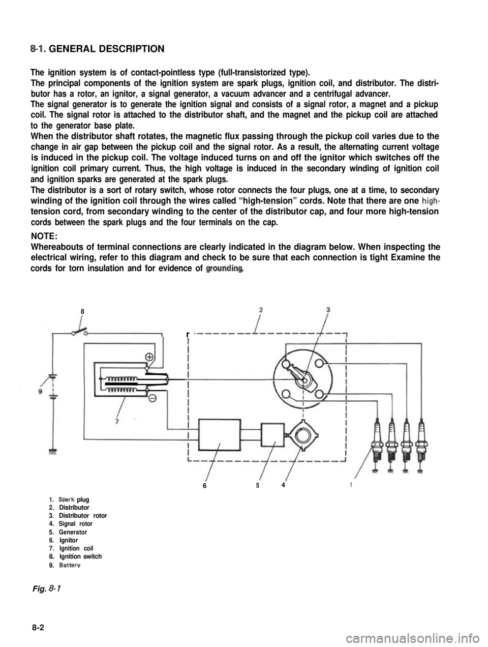
8-l. GENERAL DESCRIPTION
The ignition system is of contact-pointless type (full-transistorized type).
The principal components of the ignition system are spark plugs, ignition coil, and distributor. The distri-
butor has a rotor, an ignitor, a signal generator, a vacuum advancer and a centrifugal advancer.
The signal generator is to generate the ignition signal and consists of a signal rotor, a magnet and a pickup
coil. The signal rotor is attached to the distributor shaft, and the magnet and the pickup coil are attached
to the generator base plate.
When the distributor shaft rotates, the magnetic flux passing through the pickup coil varies due to the
change in air gap between the pickup coil and the signal rotor. As a result, the alternating current voltage
is induced in the pickup coil. The voltage induced turns on and off the ignitor which switches off the
ignition coil primary current. Thus, the high voltage is induced in the secondary winding of ignition coil
and ignition sparks are generated at the spark plugs.
The distributor is a sort of rotary switch, whose rotor connects the four plugs, one at a time, to secondary
winding of the ignition coil through the wires called “high-tension” cords. Note that there are one high-
tension cord, from secondary winding to the center of the distributor cap, and four more high-tension
cords between the spark plugs and the four terminals on the cap.
NOTE:
Whereabouts of terminal connections are clearly indicated in the diagram below. When inspecting the
electrical wiring, refer to this diagram and check to be sure that each connection is tight Examine the
cords for torn insulation and for evidence of groundinq
8
r
6541
1.Spark plug2.Distributor3.Distributor rotor4.Signal rotor
5.Generator6.lgnitor7.Ignition coil8.Ignition switch
9.Battery
Fig. 8- 1
8-2
Page 213 of 962
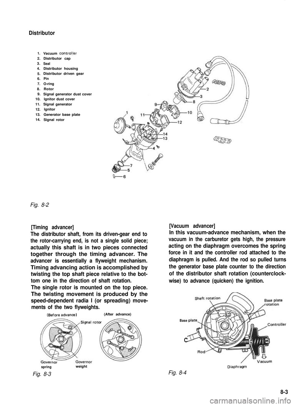
Distributor
1.Vacuum ControlJer2.Distributor cap
3.
Seal4. Distributor housing
5. Distributor driven gear
6.
Pin
7.
O-ring
8. Rotor
9. Signal generator dust cover
10. lgnitor dust cover
11. Signal generator
12. lgnitor
13. Generator base plate
14. Signal rotor
Fig. 8-2
[Timing advancer] [Vacuum advancer]
The distributor shaft, from its driven-gear end to
the rotor-carrying end, is not a single solid piece;
actually this shaft is in two pieces connected
together through the timing advancer. The
advancer is essentially a flyweight mechanism.
Timing advancing action is accomplished by
twisting the top shaft piece relative to the bot-
tom one in the direction of shaft rotation.
The single rotor is mounted on the top piece.
The twisting movement is produced by the
speed-dependent radia I (or spreading) move-
ments of the two flyweights.
In this vacuum-advance mechanism, when the
vacuum in the carburetor gets high, the pressure
acting on the diaphragm overcomes the spring
force in it and the controller rod attached to the
diaphragm is pulled. And the rod so pulled turns
the generator base plate counter to the direction
of the distributor shaft rotation (counterclock-
wise) to advance (quicken) the ignition. (Before
advanca)
(After advance)
Base
C
/ -Vacuum DiaphragTI
spring
Fig. 8-3
weight
Fig. 8-4
8-3
Page 448 of 962
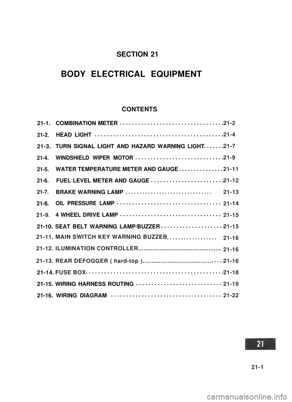
21-1.COMBINATION METER..................................
21-2.HEAD LIGHT..........................................
21-3.TURN SIGNAL LIGHT AND HAZARD WARNING LIGHT.......
21-4.WINDSHIELD WIPER MOTOR.............................
21-5.WATER TEMPERATURE METER AND GAUGE...............
21-6.FUEL LEVEL METER AND GAUGE........................
21-7.BRAKE WARNING LAMP ...............................
21-8.OIL PRESSURE LAMP..................................
4 WHEEL DRIVE LAMP.................................
21-10. SEAT BELT WARNING LAMP/BUZZER.....................
...................
...~I-I
.....
21-14. .............................................
21-15. WIRING HARNESS ROUTING............................
21-16. WIRING DIAGRAM....................................
SECTION 21
BODY ELECTRICAL EQUIPMENT
CONTENTS
21-9.
21-11. MAIN SWITCH KEY WARNING BUZZER
21-12. ILUMINATION CONTROLLER..............................................
21-13. REAR DEFOGGER ( hard-top )......................................
FUSE BOX
21-2
21-4
21-7
21-9
21-11
21-12
21-13
21-14
21-15
21-15
21-16
21-16
21-16
21-18
21-19
21-22
21-1
Page 450 of 962
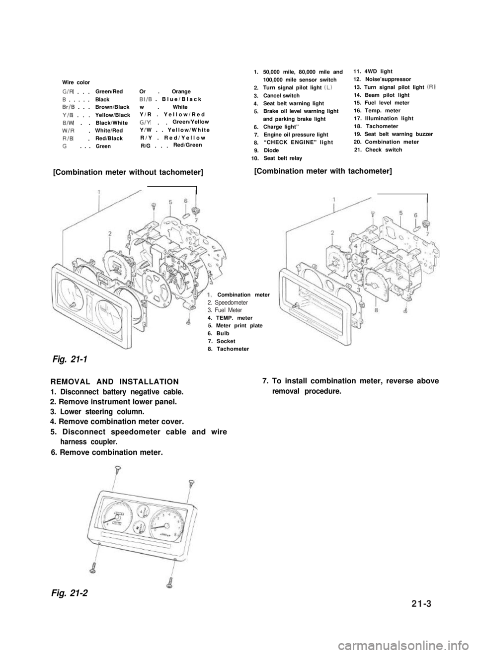
Wire color
G/R . . .Green/RedOr . Orange
0 . . . . .BlackBI/B . Blue/Black
0rlB . . .Brown/Blackw . White
Y/B . . .Yellow/BlackY/R . Yellow/Red
B/W . .Black/WhiteG/Y . .Green/Yellow
W/R .White/RedY/W . . Yellow/White
RIB .Red/BlackR/Y . Red/Yellow
G. . .GreenR/G . . .Red/Green
1.
2.
3.
4.
5.
6.7.
8.
9.
10.
50,000 mile, 80,000 mile and11. 4WD light
100,000 mile sensor switch12. Noise’suppressor
Turn signal pilot light (Lb13. Turn signal pilot light (RI
Cancel switch14. Beam pilot light
Seat belt warning light15. Fuel level meter
Brake oil level warning light16. Temp. meter
and parking brake light17. Illumination light
Charge light”18. Tachometer
Engine oil pressure light19. Seat belt warning buzzer
“CHECK ENGINE" light 20. Combination meter
Diode21. Check switch
Seat belt relay
[Combination meter without tachometer][Combination meter with tachometer]
4. TEMP. meter5. Meter print plate
6. Bulb
7. Socket
Combination meter
Fig. 21-1
8. Tachometer
REMOVAL AND INSTALLATION
1. Disconnect battery negative cable.
2. Remove instrument lower panel.
3. Lower steering column.
4. Remove combination meter cover.
5. Disconnect speedometer cable and wire
harness coupler.
7. To install combination meter, reverse above
removal procedure.
6. Remove combination meter.
Fig. 21-2
2. Speedometer3. Fuel Meter
21-3
Page 454 of 962
21-3. TURN SIGNAL LIGHT AND HAZARD WARNING LIGHT
CIRCUIT DESCRIPTION
1 Right turn signal
2.. Left turn signal
3. Battery4. Main switch
5. Fuse
6. Turn signal and hazard warning switch
7. Turn signal and hazard warning relay
Fig. 21-9
8.Green/Yellow
9.White/Yellow
10.Yellow11.Yellow/Blue
12.Green
13. Black/Blue
14. Green/Red
15.Meter pilot light(Right)
16.Meter pilot light(Left)
17.White/Green
When hazard warning switch is “OFF”, Yellow lead @ is connected to Yellow/Blue lead 0.
When the hazard warning switch is “ON”,White/Green lead @I is connected to Yellow/Blue lead @I, and
Green lead (12)to both Green/Yellow lead @ and Green/Red lead @.
When Turn-signal switch is “ON” for right turn, Green lead @ is connected to Green/Yellow lead @.
When Turn-signal switch is “ON” for left turn, Green lead @ is connected to Green/Red lead @.
21-7
Page 455 of 962
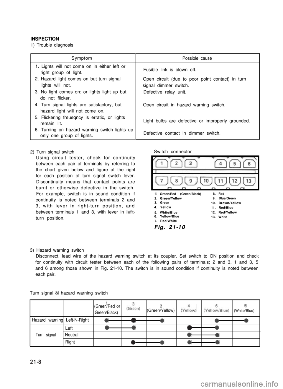
INSPECTION
1) Trouble diagnosis
Symptom
1. Lights will not come on in either left or
right group of light.
2. Hazard light comes on but turn signal
lights will not.
3. No light comes on; or lights light up but
do not flicker.
4. Turn signal lights are satisfactory, but
hazard light will not come on.
5. Flickering freueqncy is erratic, or lights
remain lit.
6. Turning on hazard warning switch lights up
only one group of lights.
2) Turn signal switch
Using circuit tester, check for continuity
between each pair of terminals by referring to
the chart given below and figure at the right
for each position of turn signal switch lever.
Discontinuity means that contact points are
burnt or otherwise defective in the switch.
For example, switch is in sound condition if
continuity is noted between terminals 2 and
3, with lever in right-turn position, and
between terminals 1 and 3, with lever in left-
turn position.
Possible cause
Fusible link is blown off.
Open circuit (due to poor point contact) in turn
signal dimmer switch.
Defective relay unit.
Open circuit in hazard warning switch.
Light bulbs are defective or improperly grounded.
Defective contact in dimmer switch.
Switch connector
I”””yrm-
1.Green/Red (Green/Black)8.Red
2.Green/Yellow9.Blue/Green3.Green10.Brown/Yellow4.Yellow11.Red/Blue
5.White/Blue12.Red/Yellow6.Yellow/Blue13.White7.Red/White
Fig. 21-10
3) Hazard warning switch
Disconnect, lead wire of the hazard warning switch at its coupler. Set switch to ON position and check
for continuity with circuit tester between each of the following pairs of terminals; 2 and 3, 1 and 3, 5
and 6 among those shown in Fig. 21-10. The switch is in sound condition if continuity is noted between
each pair.
Turn signal & hazard warning switch
1(Green/Redor
Green/Black)
(Grien)2(Green/Yellow) (Yeiow)5(YelloiIBlue) (White/Blue)
Hazard warning Left-N-Right0a-000
Left00l0
Turn signalNeutral*0
Rightla*0
21-8