Page 319 of 962
SECTION 16
DIFFERENTIAL
CONTENTS
16-1. GENERAL DESCRIPTION............................... 16-2
16.2. REMOVAL...........................................16-3
16-3. DISASSEMBLY........................................16-6
16-4. INSPECTION AND ADJUSTMENT OF COMPONENTS.........16-7
16.5. REASSEMBLY.......................................16-13
16-6. INSTALLATION......................................16-15
16-7. MAINTENANCE SERVICES.............................16-16
16-8. RECOMMENDED TORQUE SPECIFICATIONS..............16-16
16-1
Page 320 of 962

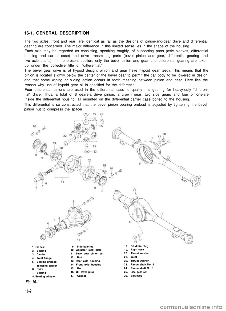
16-1. GENERAL DESCRIPTION
The two axles, front and rear, are identical as far as the designs of pinion-and-gear drive and differential
gearing are concerned. The major difference in this limited sense lies in the shape of the housing.
Each axle may be regarded as consisting, speaking roughly, of supporting parts (axle sleeves, differential
housing and carrier case) and drive transmitting parts (bevel pinion and gear, differential gearing and
live axle shafts). In the present section, only the bevel pinion and gear and differential gearing are taken
up under the collective title of “differential.”
The bevel gear drive is of hypoid design; pinion and gear have hypoid gear teeth. This means that the
pinion is located slightly below the center of the bevel gear to permit the car body to be lowered in design,
and that some wiping or sliding action occurs in tooth meshing between pinion and gear. Here lies the
reason why use of hypoid gear oil is specified for the differential.
Four differential pinions are used in the differential case to qualify this gearing for heavy-duty “differen-
tial” drive. Thus, a total of 8 gears-a drive pinion, a crown gear, two side gears and four pinions-are
inside the differential housing, all mounted on the differential carrier case bolted to the housing.
This differential is so constructed that the bevel pinion bearing preload is adjusted by tightening the bevel
pinion nut to compress the spacer.
1. Oil seal
2.Bearing3.Carrier4.Joint flange
5.Bearing preload
adjusting spacer6.Shim7.Bearing
8. Bearing adjuster
9.Side bearing10. Adjuster lock plate11. Bevel gear pinion set
12.Bolt13. Rear axle housing14. Front axle housing
15.Bolt16. Oil level plug
17.Gasket
18.Oil drain plug19.Right case
20.Thrust washer
21.Joint
22.Thrust washer
23.Pinion shaft No. 2
24.Pinion shaft No. 1
25.Side gear set
26.Left case
16-2
Fig. 16-1
Page 321 of 962

16-2. REMOVAL
1. Loosen, but do not remove, wheel nuts of
front or rear wheels, and raise car off the
2.
3.
floor by jacking.
Rest car steady on safety stands.
Drain out oil in differential housing by
loosening drain plug.
Remove wheel nuts and take off wheels,
front or rear. Each wheel has five wheel nuts.
For Front Differential
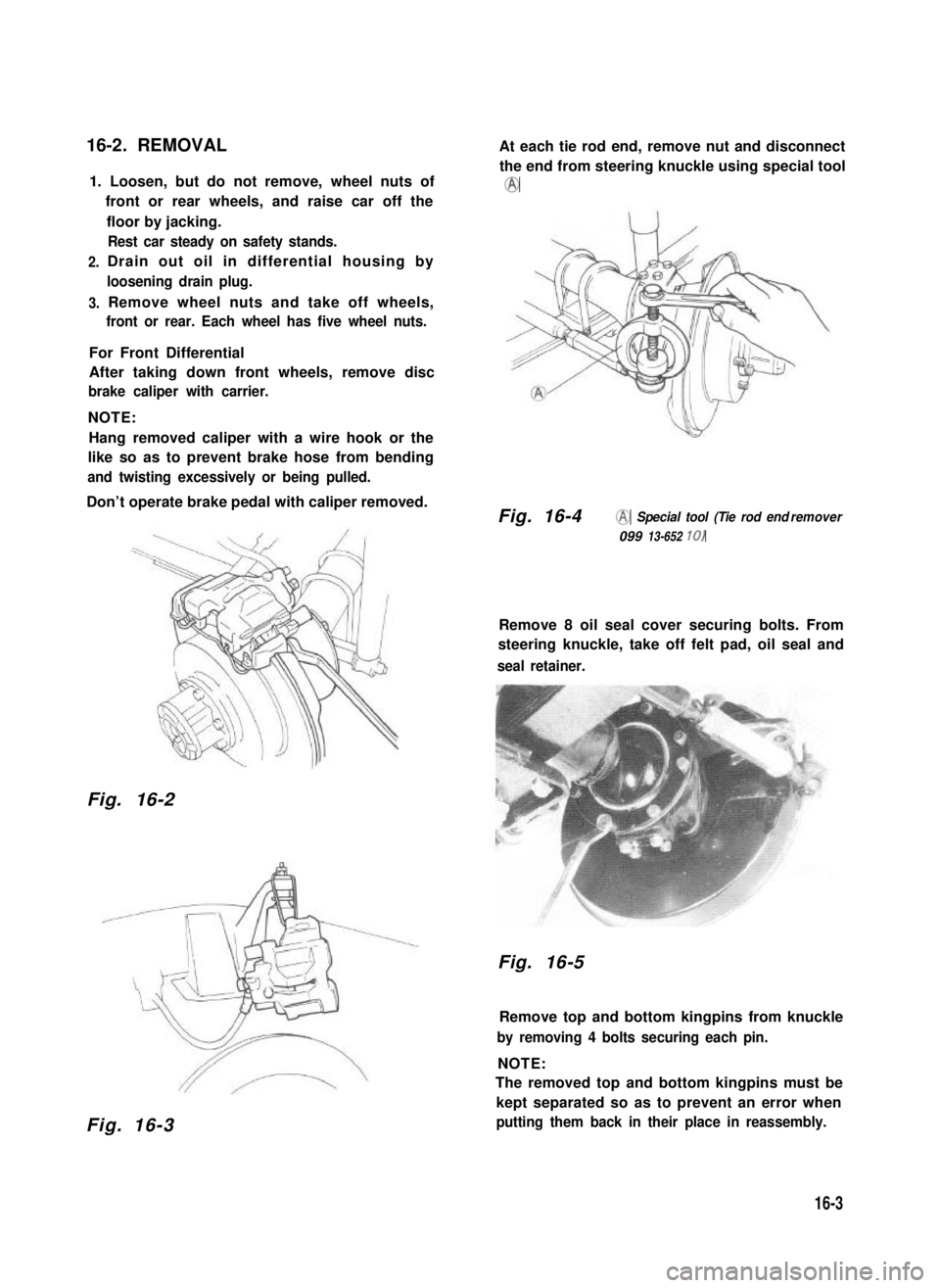
After taking down front wheels, remove disc
brake caliper with carrier.
NOTE:
Hang removed caliper with a wire hook or the
like so as to prevent brake hose from bending
and twisting excessively or being pulled.
Don’t operate brake pedal with caliper removed.
Fig. 16-2
Fig. 16-3
At each tie rod end, remove nut and disconnect
the end from steering knuckle using special tool
@
Fig. 16-4@ Special tool (Tie rod end remover
099 13-652 10)
Remove 8 oil seal cover securing bolts. From
steering knuckle, take off felt pad, oil seal and
seal retainer.
Fig. 16-5
Remove top and bottom kingpins from knuckle
by removing 4 bolts securing each pin.
NOTE:
The removed top and bottom kingpins must be
kept separated so as to prevent an error when
putting them back in their place in reassembly.
16-3
Page 322 of 962
Fig. 16-6Fig. 16-8
Draw out live axle shaft from axle housing.
NOTE:
At this time, lower kingpin bearing sometimes
falls off. So remove bearing while pulling off
knuckle gradually.
Fig. 16-7
At differential housing, disconnect propeller
shaft by removing bolts securing flange yoke to
companion flange. Remove 8 bolts holding fast
differential carrier case to housing, and take
down carrier assembly.
For Rear Differential
After taking down rear wheels, remove brake
drums by using special tools.
NOTE:
Before removing brake drum, check to ensure
that parking brake lever is not pulled up.
To increase clearance between brake shoe and
brake drum, remove parking brake shoe lever
return spring @ and disconnect parking brake
cable joint @ from parking brake shoe lever 0.
Remove parking brake shoe lever stopper plate.
1. Parking brake shoe leverreturn spring2. Parking brake shoe lever 3. Parking brake cable joint
4. Pin
5. Clip
6. Brake back plate
Fig. 16-9
16-4
Page 323 of 962
Fig. 16-19-1 @ Special tool (Brake drum remover
09943-355 7 1)
Fig. 16-10 @ Special tool (Rear axle remover
09922-66010)
@ Special tool (Sliding hammer@ Special tool (Sliding hammer
09942- 15510)09942-15510)
Disconnect brake pipe from wheel cylinder.
Have a small plug ready for use when disconnect-
ing pipe. As pipe comes off the wheel cylinder,
plug the pipe to prevent brake fluid from
leaking out.
And remove 4 brake backing plate securing
bolts.
Fig. 16-9-2 @ Plug
Using special tools indicated below, draw out
each axle shaft with brake backing plate.
Disconnect propeller shaft as in the case of front
axle, and detach and take down differential
carrier case from housing by removing 8 bolts.
Fig. 16-11
16-5
Page 324 of 962
16-3. DISASSEMBLY
Lock flange immovable by using special tool,
and remove nut from the end of bevel pinion
shank.
Fig. 16-12 @ Special tool (Rotor holder 09930-
40 113)
Scribe marks on each cap bolted to the saddle
portion of carrier case and holding down the
side bearing. The marks are to identify caps.
This means that there are right and left caps, so
identified and so handled at the time of reas-
sembly.
Fig. 16-13 @ Scribed match marks
At each side, loosen bolts on bearing adjuster
stopper,remove bearing cap securing bolts,
and take off cap. Lift differential case assembly,
complete with bevel gear, off the carrier.
Fig. 16-14
Remove 10 bolts securing bevel gear to diffe-
rential case, and separate gear from case.
Fig. 16-15
There are 8 bolts fastening two differential
case halves together. Remove these bolts to
sever right-hand case half from left-hand one,
and take off right-hand one.
Fig. 16-16 @ Special tool (Rotor holder
09930-40 113)
16-6
Page 325 of 962

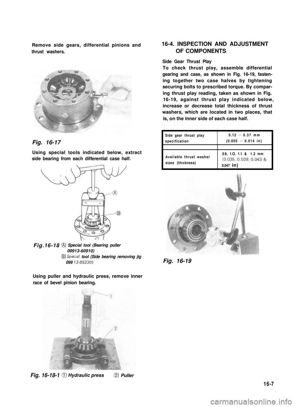
Remove side gears, differential pinions and
thrust washers.
Fig. 16-17
Using special tools indicated below, extract
side bearing from each differential case half.
Fig.16-18@ Special tool (Bearing puller
09913-60910)
@ SptCal tool (Side bearing removing jig
099 13-85230)
Using puller and hydraulic press, remove inner
race of bevel pinion bearing.
16-4. INSPECTION AND ADJUSTMENT
OF COMPONENTS
Side Gear Thrust Play
To check thrust play, assemble differential
gearing and case, as shown in Fig. 16-19, fasten-
ing together two case halves by tightening
securing bolts to prescribed torque. By compar-
ing thrust play reading, taken as shown in Fig.
16-19, against thrust play indicated below,
increase or decrease total thickness of thrust
washers, which are located in two places, that
is, on the inner side of each case half.
Side gear thrust play0.12 - 0.37 mm
specification(0.005 - 0.014 in)
Available thrust washer
sizes (thickness)
0.9, 1.O, 1.1 & 1.2 mm
(0.035,0.039,0.043 &
0.047 in)
Fig. 16-19
Fig. 16-18-1 0 Hydraulic press@ Puller
16-7
Page 327 of 962

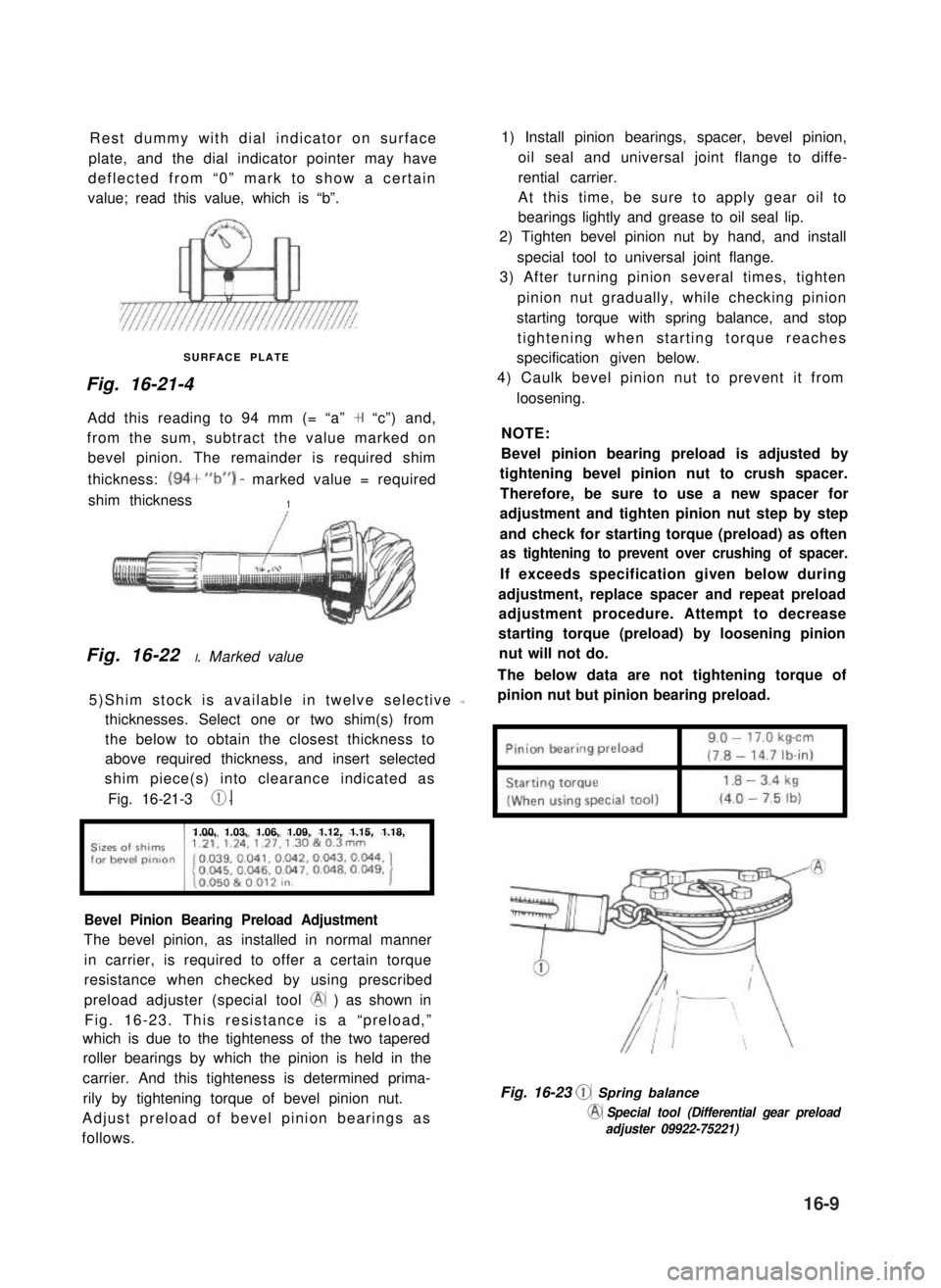
Rest dummy with dial indicator on surface
plate, and the dial indicator pointer may have
deflected from “0” mark to show a certain
value; read this value, which is “b”.
SURFACE PLATE
Fig. 16-21-4
Add this reading to 94 mm (= “a” + “c”) and,
from the sum, subtract the value marked on
bevel pinion. The remainder is required shim
thickness: (94+“b”) - marked value = required
shim thickness1
Fig. 16-22 I. Marked value
5)Shim stock is available in twelve selective L
thicknesses. Select one or two shim(s) from
the below to obtain the closest thickness to
above required thickness, and insert selected
shim piece(s) into clearance indicated as
Fig. 16-21-3 0.
1.00, 1.03, 1.06, 1.09, 1.12, 1.15, 1.18,
Bevel Pinion Bearing Preload Adjustment
The bevel pinion, as installed in normal manner
in carrier, is required to offer a certain torque
resistance when checked by using prescribed
preload adjuster (special tool @ ) as shown in
Fig. 16-23. This resistance is a “preload,”
which is due to the tighteness of the two tapered
roller bearings by which the pinion is held in the
carrier. And this tighteness is determined prima-
rily by tightening torque of bevel pinion nut.
Adjust preload of bevel pinion bearings as
follows.
1) Install pinion bearings, spacer, bevel pinion,
oil seal and universal joint flange to diffe-
rential carrier.
At this time, be sure to apply gear oil to
bearings lightly and grease to oil seal lip.
2) Tighten bevel pinion nut by hand, and install
special tool to universal joint flange.
3) After turning pinion several times, tighten
pinion nut gradually, while checking pinion
starting torque with spring balance, and stop
tightening when starting torque reaches
specification given below.
4) Caulk bevel pinion nut to prevent it from
loosening.
NOTE:
Bevel pinion bearing preload is adjusted by
tightening bevel pinion nut to crush spacer.
Therefore, be sure to use a new spacer for
adjustment and tighten pinion nut step by step
and check for starting torque (preload) as often
as tightening to prevent over crushing of spacer.
If exceeds specification given below during
adjustment, replace spacer and repeat preload
adjustment procedure. Attempt to decrease
starting torque (preload) by loosening pinion
nut will not do.
The below data are not tightening torque of
pinion nut but pinion bearing preload.
Fig. 16-23 @ Spring balance
@ Special tool (Differential gear preload
adjuster 09922-75221)
16-9