Page 423 of 962
Fig. 19-6-1
19-38
19-6. PARKING BRAKE
Page 429 of 962

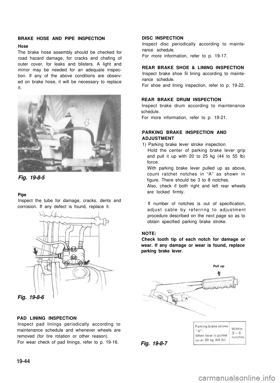
BRAKE HOSE AND PIPE INSPECTION
Hose
The brake hose assembly should be checked for
road hazard damage, for cracks and chafing of
outer cover, for leaks and blisters. A light and
mirror may be needed for an adequate inspec-
tion. If any of the above conditions are observ-
ed on brake hose, it will be necessary to replace
it.
DISC INSPECTION
Inspect disc periodically according to mainte-
nance schedule.
For more information, refer to p. 19-17.
REAR BRAKE SHOE & LINING INSPECTION
Inspect brake shoe & lining according to mainte-
nance schedule.
For shoe and lining inspection, refer to p. 19-22.
Fig. 19-8-5
Pipe
Inspect the tube for damage, cracks, dents and
corrosion. If any defect is found, replace it.
Fig. 19-8-6\ ’
PAD LINING INSPECTION
Inspect pad linings periodically according to
maintenance schedule and whenever wheels are
removed (for tire rotation or other reason).
For wear check of pad linings, refer to p. 19-16.
REAR BRAKE DRUM INSPECTION
Inspect brake drum according to maintenance
schedule.
For more information, refer to p. 19-21.
PARKING BRAKE INSPECTION AND
ADJUSTMENT
1) Parking brake lever stroke inspection.
Hold the center of parking brake lever grip
and pull it up with 20 to 25 kg (44 to 55 lb)
force.
With parking brake lever pulled up as above,
count ratchet notches in “A” as shown in
figure. There should be 3 to 8 notches.
Also, check if both right and left rear wheels
are locked firmly.
If number of notches is out of specification,
adjust cable by referring to adjustment
procedure described on the next page so as to
obtain specified parking brake stroke.
NOTE:
Check tooth tip of each notch for damage or
wear. If any damage or wear is found, replace
parking brake lever.
Pull up
4
Fig. 19-8-7
19-44
Page 430 of 962

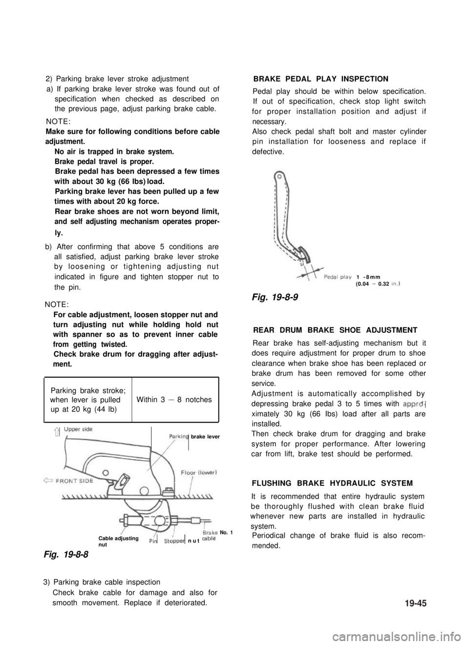
2) Parking brake lever stroke adjustment
a) If parking brake lever stroke was found out of
specification when checked as described on
the previous page, adjust parking brake cable.
NOTE:
Make sure for following conditions before cable
adjustment.
No air is trapped in brake system.
Brake pedal travel is proper.
Brake pedal has been depressed a few times
with about 30 kg (66 lbs) load.
Parking brake lever has been pulled up a few
times with about 20 kg force.
Rear brake shoes are not worn beyond limit,
and self adjusting mechanism operates proper-
ly.
b) After confirming that above 5 conditions are
all satisfied, adjust parking brake lever stroke
by loosening or tightening adjusting nut
indicated in figure and tighten stopper nut to
the pin.
NOTE:
For cable adjustment, loosen stopper nut and
turn adjusting nut while holding hold nut
with spanner so as to prevent inner cable
from getting twisted.
Check brake drum for dragging after adjust-
ment.
Parking brake stroke;
when lever is pulledWithin 3 - 8 notches
up at 20 kg (44 lb)
’ yLyFrking brake lever
Cable adjustingnutPi:St&per nut cab’e
Fig. 19-8-8
No. 1
BRAKE PEDAL PLAY INSPECTION
Pedal play should be within below specification.
If out of specification, check stop light switch
for proper installation position and adjust if
necessary.
Also check pedal shaft bolt and master cylinder
pin installation for looseness and replace if
defective.
play1 -8mm(0.04 - 0.32tn.1
Fig. 19-8-9
REAR DRUM BRAKE SHOE ADJUSTMENT
Rear brake has self-adjusting mechanism but it
does require adjustment for proper drum to shoe
clearance when brake shoe has been replaced or
brake drum has been removed for some other
service.
Adjustment is automatically accomplished by
depressing brake pedal 3 to 5 times with apprd-
ximately 30 kg (66 Ibs) load after all parts are
installed.
Then check brake drum for dragging and brake
system for proper performance. After lowering
car from lift, brake test should be performed.
FLUSHING BRAKE HYDRAULIC SYSTEM
It is recommended that entire hydraulic system
be thoroughly flushed with clean brake fluid
whenever new parts are installed in hydraulic
system.
Periodical change of brake fluid is also recom-
mended.
3) Parking brake cable inspection
Check brake cable for damage and also for
smooth movement. Replace if deteriorated.19-45
Page 450 of 962

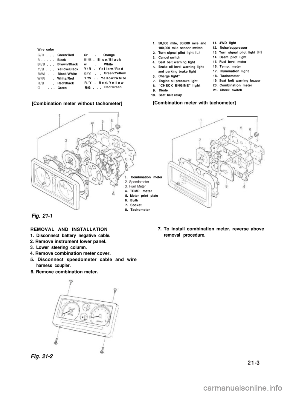
Wire color
G/R . . .Green/RedOr . Orange
0 . . . . .BlackBI/B . Blue/Black
0rlB . . .Brown/Blackw . White
Y/B . . .Yellow/BlackY/R . Yellow/Red
B/W . .Black/WhiteG/Y . .Green/Yellow
W/R .White/RedY/W . . Yellow/White
RIB .Red/BlackR/Y . Red/Yellow
G. . .GreenR/G . . .Red/Green
1.
2.
3.
4.
5.
6.7.
8.
9.
10.
50,000 mile, 80,000 mile and11. 4WD light
100,000 mile sensor switch12. Noise’suppressor
Turn signal pilot light (Lb13. Turn signal pilot light (RI
Cancel switch14. Beam pilot light
Seat belt warning light15. Fuel level meter
Brake oil level warning light16. Temp. meter
and parking brake light17. Illumination light
Charge light”18. Tachometer
Engine oil pressure light19. Seat belt warning buzzer
“CHECK ENGINE" light 20. Combination meter
Diode21. Check switch
Seat belt relay
[Combination meter without tachometer][Combination meter with tachometer]
4. TEMP. meter5. Meter print plate
6. Bulb
7. Socket
Combination meter
Fig. 21-1
8. Tachometer
REMOVAL AND INSTALLATION
1. Disconnect battery negative cable.
2. Remove instrument lower panel.
3. Lower steering column.
4. Remove combination meter cover.
5. Disconnect speedometer cable and wire
harness coupler.
7. To install combination meter, reverse above
removal procedure.
6. Remove combination meter.
Fig. 21-2
2. Speedometer3. Fuel Meter
21-3
Page 460 of 962
![SUZUKI GRAND VITARA 1987 Service Repair Manual [Gauge unit]21-7. BRAKE WARNING LAMP
Use ohmmeter to confirm that level gauge unit
changes in resistance with change of the float
position. Float position-to-resistance relation-
ship can be plotted i SUZUKI GRAND VITARA 1987 Service Repair Manual [Gauge unit]21-7. BRAKE WARNING LAMP
Use ohmmeter to confirm that level gauge unit
changes in resistance with change of the float
position. Float position-to-resistance relation-
ship can be plotted i](/manual-img/20/57437/w960_57437-459.png)
[Gauge unit]21-7. BRAKE WARNING LAMP
Use ohmmeter to confirm that level gauge unit
changes in resistance with change of the float
position. Float position-to-resistance relation-
ship can be plotted in a graph as shown below.
The brake warning lamp system consists of the
brake fluid level switch installed to the master
cylinder reservoir and the lamp inside the
combination meter.
This circuit includes a parking brake switch
which gives a warning for unreleased parking
brake.
F-E
Fig. 21-20 Resistance-Fuel Level Relationship
Fig. 21-21
F : Full
E : Empty
OPERATION
Brake fluid level warning lamp circuit consists of
brake fluid level switch installed in master
cylinder reservoir, brake fluid level warning lamp
in gage cluster and check relay.
Also, this circuit is additionally provided with
parking brake switch which warns that parking
brake is applied.when engine is stopped,
warning lamp comes on, if ignition switch is
turned ON and parking brake is applied.
For bulb check, warning lamp comes on briefly
during engine starting regardless of brake fluid
level position and parking brake operation.
Because point of check relay is closed.
After engine is started, release parking brake.
If lamp gose off, brake fluid level is adequate.
When warning lamp dose not operate, use circuit
diagram as reference to check bulb, wiring, etc.
r---i
check relayl-2-l
B/Y : Black/Yellow1. Fluid level switch
R/B : Red/Black2. Warning lamp
B: Black3. Parking brake switch
B/W : Black/White4. Main switch
B/BI : Black/Blue5. Battery
Fig. 27-22
21-13
Page 472 of 962
Convertible/Hard Top
WHEEL AND SUSPENSIONI
Tire size: front and rear1 P205/70 R15I
Tire pressurefront
rear
Suspension typefront
rear
140 kPa (1.40 kg/cm’, 20 psi)
140 kPa (1.40 kg/cm’, 20 psi)-unladen
180 kPa (1.80 kg/cm*, 26 psi)-laden
Leaf spring
Leaf spring
STEERING
Turning radius1 5.1 m (16.7ft)
1 Steering gear box1Ball nut typeI
Toe-in
Camber angle
Caster angle
King pin angle
BRAKE SYSTEM
Type
Wheel brake
Parking brake
CAPACITIES
Cooling solution
Fuel tank
2 - 6 mm (0.08 - 0.24 in.)
lo 00’
) 3º 30’I
front
rear
9º 00’
4-wheel, hydraulic
Disc brake (floating caliper type)
Drum brake (leading and trailing)
Mechanical actuated on rear wheels
4.8 Q (10.1/8.4 US/Imp pt)
4OQ (10.6/8.8 US/Imp cral)
Engine oil
Transmission oil
Differential gear
box oil
Transfer gear box oil
front
rear
3.5 II (7.4/6.2 US/Imp pt)
1.3 II (2.7/2.3 US/Imp pt)
2.0 Q (4.2/3.5 US/Imp pt)
1.5 II (3.2/2.6 US/Imp pt)
0.8 !? (1.7/l .4 US/Imp pt)
22-3
Page:
< prev 1-8 9-16 17-24