1987 SUZUKI GRAND VITARA check oil
[x] Cancel search: check oilPage 95 of 962
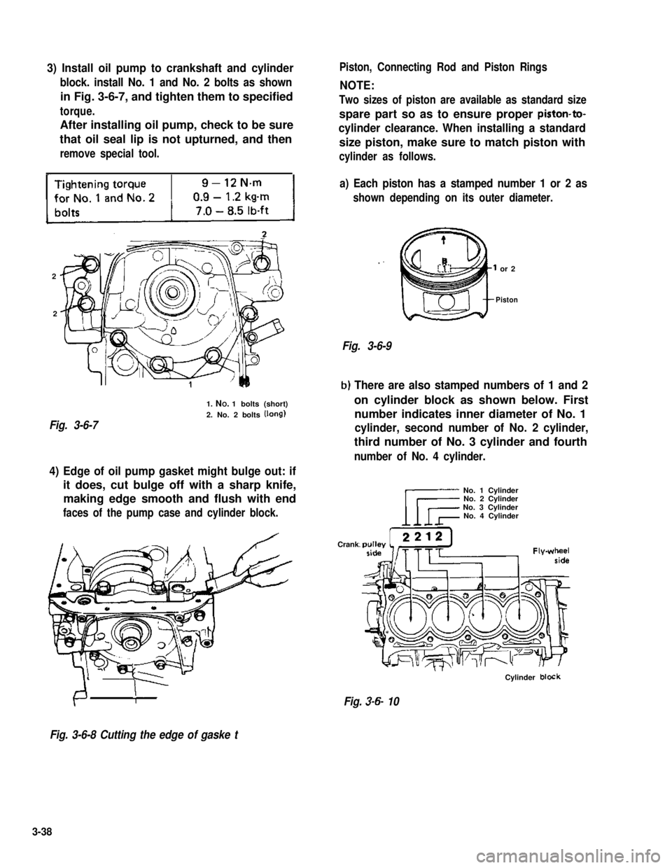
3) Install oil pump to crankshaft and cylinder
block. install No. 1 and No. 2 bolts as shown
in Fig. 3-6-7, and tighten them to specified
torque.
After installing oil pump, check to be sure
that oil seal lip is not upturned, and then
remove special tool.
-
2
2
Fig. 3-6-7
1. NO. 1 bolts (short)
2. No. 2 bolts (long)
Piston, Connecting Rod and Piston Rings
NOTE:
Two sizes of piston are available as standard size
spare part so as to ensure proper piston-to-
cylinder clearance. When installing a standard
size piston, make sure to match piston with
cylinder as follows.
a) Each piston has a stamped number 1 or 2 as
shown depending on its outer diameter.
or 2
Piston
Fig. 3-6-9
b) There are also stamped numbers of 1 and 2
on cylinder block as shown below. First
number indicates inner diameter of No. 1
cylinder, second number of No. 2 cylinder,
third number of No. 3 cylinder and fourth
number of No. 4 cylinder.
4) Edge of oil pump gasket might bulge out: if
it does, cut bulge off with a sharp knife,
making edge smooth and flush with end
faces of the pump case and cylinder block.
Crank
No. 1 CylinderNo. 2 CylinderNo. 3 CylinderNo. 4 Cylinder
Cylinder block
Fig. 3-6- 10
Fig. 3-6-8 Cutting the edge of gaske t
3-38
Page 101 of 962
2) Install valve spring seat to cylinder head.
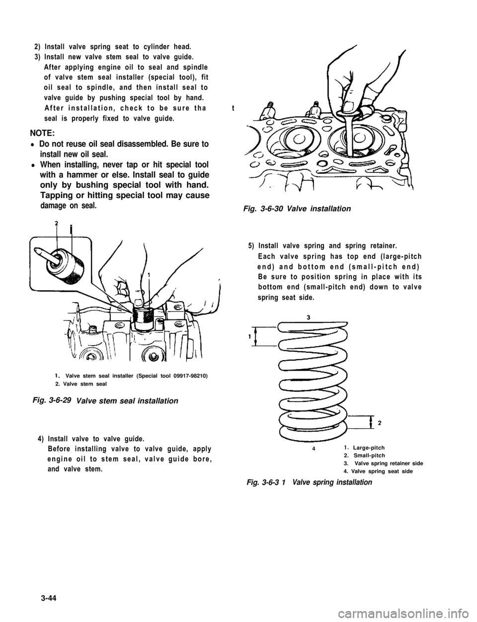
3) Install new valve stem seal to valve guide.
After applying engine oil to seal and spindle
of valve stem seal installer (special tool), fit
oil seal to spindle, and then install seal to
valve guide by pushing special tool by hand.
After installation, check to be sure that
seal is properly fixed to valve guide.
NOTE:
l Do not reuse oil seal disassembled. Be sure to
install new oil seal.
l When installing, never tap or hit special tool
with a hammer or else. Install seal to guide
only by bushing special tool with hand.
Tapping or hitting special tool may cause
damage on seal.
7 i
1.Valve stem seal installer (Special tool 09917-98210)
2. Valve stem seal
Fig. 3-6-29 Valve stem seal installation
4) Install valve to valve guide.
Before installing valve to valve guide, apply
engine oil to stem seal, valve guide bore,
and valve stem.
Fig. 3-6-30 Valve installation
5) Install valve spring and spring retainer.
Each valve spring has top end (large-pitch
end) and bottom end (small-pitch end)
Be sure to position spring in place with its
bottom end (small-pitch end) down to valve
spring seat side.
41. Large-pitch2. Small-pitch
3.Valve spring retainer side
4. Valve spring seat side
Fig. 3-6-3 1Valve spring installation
3-44
Page 110 of 962
3-7. ENGINE INSTALLATION
1) Lower engine with transmission into vehicle,
but do not remove lifting device.
2) Tighten engine mounting bracket bolts
(right and left) and transmission mounting
bolts to specification. Refer to p. 3-58.
3) Remove lifting device.
4) Reverse removal procedures for installation
of remainder.
5) Adjust accelerator cable play and clutch
cable play.
6) Connect vacuum hoses securely. Refer to
section 5 “EMISSION CONTROL SYSTEM”
for correct connection.
7) Connect wire harnesses and couplers secure-
IY.
8) Tighten bolts and nuts to specified torque.
For individual specification, refer to each
section.
9) Fill specified amount of specified trans-
mission oil and engine oil. For the detail,
refer to SECTION 1 PERIODIC MAINTE-
NANCE SERVICE of this manual.
10) After adjusting water pump belt tension to
specification, fill specified amount of engine
cooling water.
11) Before starting engine, check again to ensure
that all parts once disassembled or discon-
nected are back in place securely.
12)Start engine and check ignition timing. If
it is not to specified timing, adjust it, referr-
ing to SECTION 8 of this manual.
13) After engine is started, check for oil leak,
abnormal noise and other malcondition.
Also, check each part for operation.
3-8. ENGINE MAINTENANCE SERVICE
Fan Belt
Adjust belt tension as outlined in SECTION 6
ENGINE COOLING SYSTEM (p. 6-10).
Ignition Timing
Refer to IGNITION TIMING, Page 8-9.
Carburetor
fidjustments to be made are detailed in SEC-
TION 4 (p. 4-19).
Valve Lash (Clearance)
Valve lash specifications:
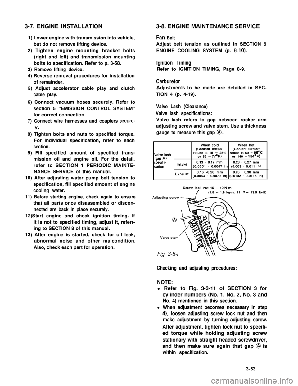
Valve lash refers to gap between rocker arm
adjusting screw and valve stem. Use a thickness
gauge to measure this gap @.
When coldWhen hot(Coolant tempe-(Coolant tempa-
Valve lashrature is 15 - 25%rature is 60 - 66’C
(gap A)or 69 - 77’F)or 140 - 154’F)
specif i-0.13 - 0.17 mm0.23 - 0.27 mmcationIntake(0.0051 - 0.0067 in) (0.009 - 0.011 in)
Exhaust0.16 -0.20 mm0.26 - 0.30 mm(0.0063 - 0.0079 in) (0.0102 - 0.0116 in)
Screw lock nut 15 - 19 N.m(1.5 - 1.9 kg-m, 11 .O - 13.5 lb-ft)
Adjusting screw
8
Valve stem
Fig. 3-8-l
Checking and adjusting procedures:
NOTE:
l Refer to Fig. 3-3-11 of SECTION 3 for
cylinder numbers (No. 1, No. 2, No. 3 and
No. 4) mentioned in this section.
l When adjustment becomes necessary in step
4), loosen adjusting screw lock nut and then
make adjustment by turning adjusting screw.
After adjustment, tighten lock nut to specifi-
ed torque while holding adjusting screw
stationary with straight headed screwdriver,
and then make sure again that gap @ is
within specification.
3-53
Page 111 of 962
1) Remove cylinder head cover.
2) Remove ignitiontiming check window
rubber plug from clutch housing of trans-
mission case.
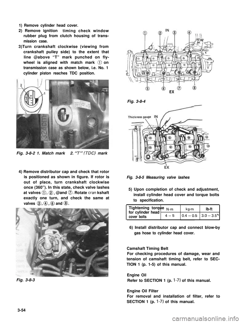
3)Turn crankshaft clockwise (viewing from
crankshaft pulley side) to the extent that
line @above “T” mark punched on fly-
wheel is aligned with match mark @ on
transmission case as shown below, i.e. No. 1
cylinder piston reaches TDC position.
Fig. 3-8-2 1. Match mark2. ‘7” (TDC) mark
4) Remove distributor cap and check that rotor
is positioned as shown in figure. If rotor is
out of place, turn crankshaft clockwise
once (360”). In this state, check valve lashes
at valves @,@I, @and 0. Rotate cran kshaft
exactly one turn, and check the same at
valves 8, @, @ and @I.
Fig. 3-8-3
EX
Fig. 3-8-4-
Fig. 3-8-5 Measuring valve lashes
5) Upon completion of check and adjustment,
install cylinder head cover and torque bolts
to specification.
Tightening torque N.,.,.,
for cylinder head Ib-mlb-ft
cover bolts4-50.4 - 0.53.0 - 3.5*
6) Install distributor cap and connect blow-by
gas hose to cylinder head cover.
Camshaft Timing Belt
For checking procedures of damage, wear and
tension of camshaft timing belt, refer to SEC-
TION 1 (p. 1-5) of this manual.
Engine Oil
Refer to SECTION 1 (p. I-7) of this manual.
Engine Oil Filter
For removal and installation of filter, refer to
SECTION 1 (p. I-7) of this manual.
3-54
Page 112 of 962
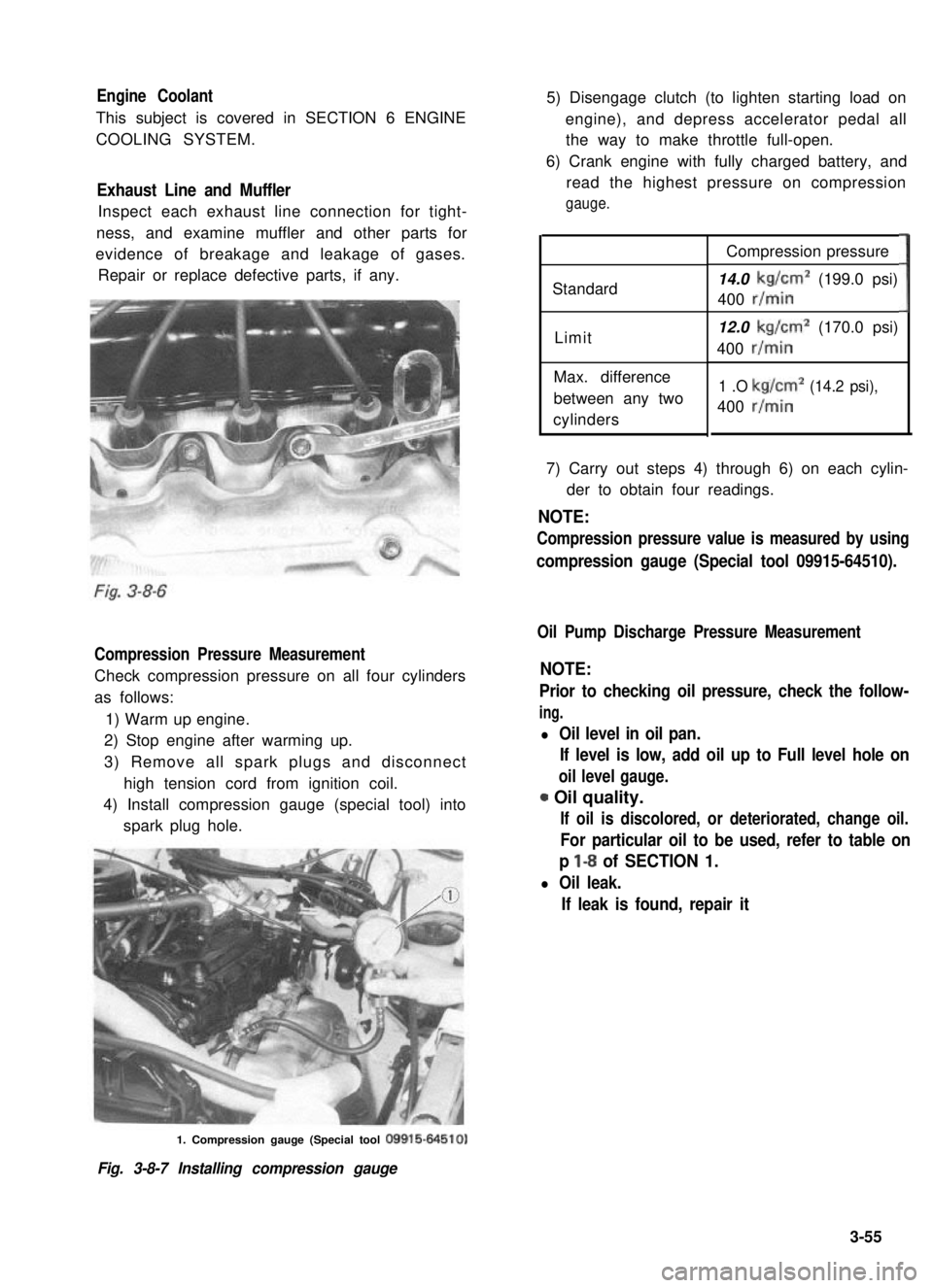
Engine Coolant
This subject is covered in SECTION 6 ENGINE
COOLING SYSTEM.
Exhaust Line and Muffler
Inspect each exhaust line connection for tight-
ness, and examine muffler and other parts for
evidence of breakage and leakage of gases.
Repair or replace defective parts, if any.
Compression Pressure Measurement
Check compression pressure on all four cylinders
as follows:
1) Warm up engine.
2) Stop engine after warming up.
3) Remove all spark plugs and disconnect
high tension cord from ignition coil.
4) Install compression gauge (special tool) into
spark plug hole.
5) Disengage clutch (to lighten starting load on
engine), and depress accelerator pedal all
the way to make throttle full-open.
6) Crank engine with fully charged battery, and
read the highest pressure on compression
gauge.
Standard
Limit
Max. difference
between any two
cylinders
Compression pressure
14.0 kg/cm2 (199.0 psi)
400 r/min
12.0 kg/cm2 (170.0 psi)
400 r/min
1 .O kg/cm2 (14.2 psi),
400 r/min
3
7) Carry out steps 4) through 6) on each cylin-
der to obtain four readings.
NOTE:
Compression pressure value is measured by using
compression gauge (Special tool 09915-64510).
Oil Pump Discharge Pressure Measurement
NOTE:
Prior to checking oil pressure, check the follow-
ing.
l Oil level in oil pan.
If level is low, add oil up to Full level hole on
oil level gauge.
0 Oil quality.
If oil is discolored, or deteriorated, change oil.
For particular oil to be used, refer to table on
p l-8 of SECTION 1.
l Oil leak.
If leak is found, repair it
1. Compression gauge (Special tool 09915-64510)
Fig. 3-8-7 Installing compression gauge
3-55
Page 113 of 962
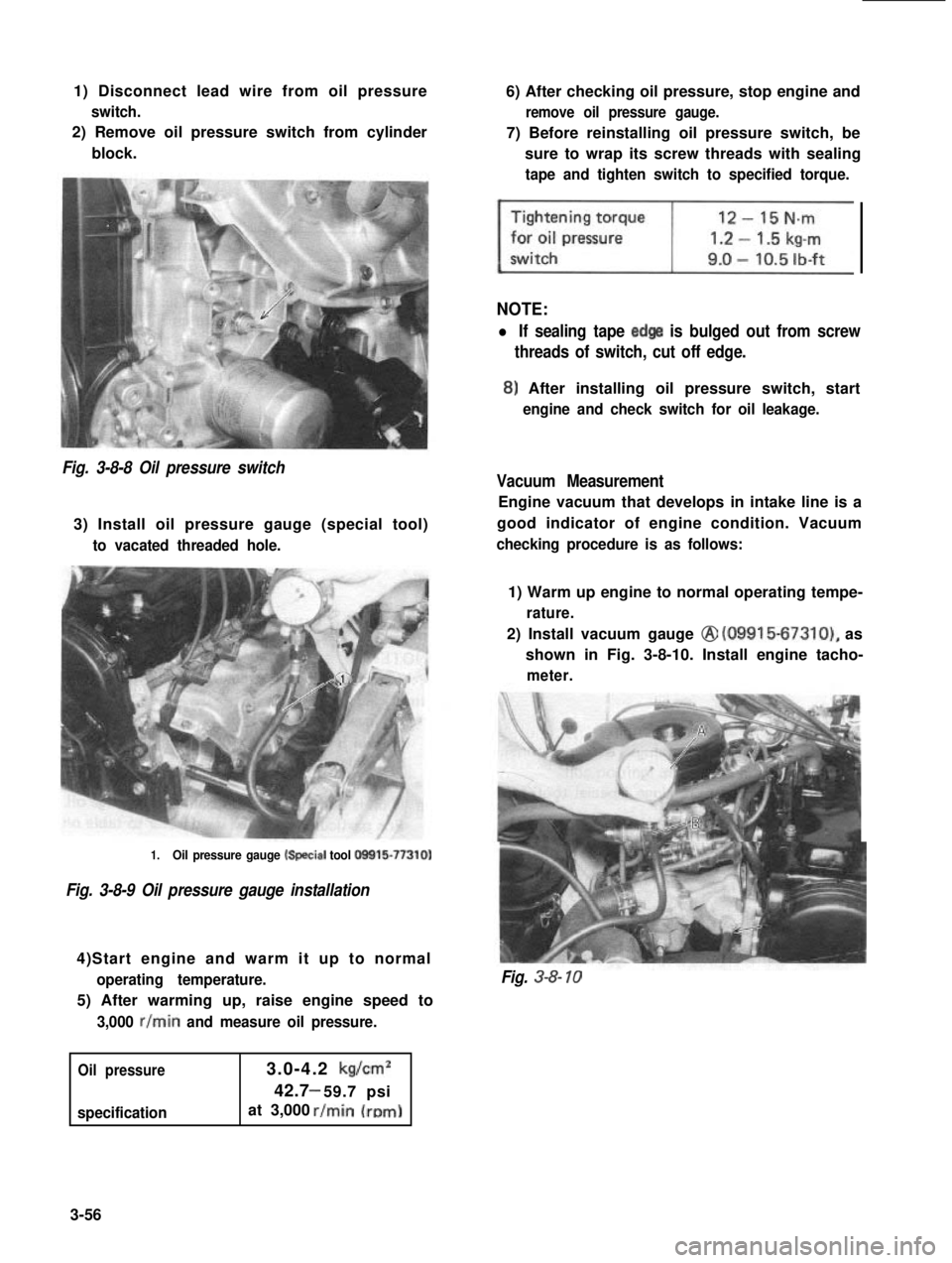
1) Disconnect lead wire from oil pressure
switch.
2) Remove oil pressure switch from cylinder
block.
6) After checking oil pressure, stop engine and
remove oil pressure gauge.
7) Before reinstalling oil pressure switch, be
sure to wrap its screw threads with sealing
tape and tighten switch to specified torque.
NOTE:
l If sealing tape edge is bulged out from screw
threads of switch, cut off edge.
8) After installing oil pressure switch, start
engine and check switch for oil leakage.
Fig. 3-8-8 Oil pressure switch
3) Install oil pressure gauge (special tool)
to vacated threaded hole.
Vacuum Measurement
Engine vacuum that develops in intake line is a
good indicator of engine condition. Vacuum
checking procedure is as follows:
1.Oil pressure gauge k+ecial tool O!Xil5-77310)
Fig. 3-8-9 Oil pressure gauge installation
4)Start engine and warm it up to normal
operating temperature.
5) After warming up, raise engine speed to
3,000 r/min and measure oil pressure.
Oil pressure
specification
3.0-4.2 kg/cm2
42.7 59.7 psi-
at 3,000
1) Warm up engine to normal operating tempe-
rature.
2) Install vacuum gauge @ (09915-67310), as
shown in Fig. 3-8-10. Install engine tacho-
meter.
Fig. 3-8- 10
3-56
Page 114 of 962
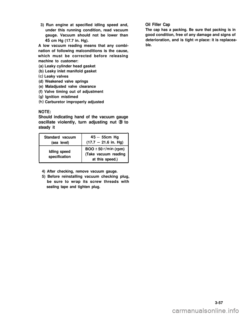
3) Run engine at specified idling speed and,
under this running condition, read vacuum
gauge. Vacuum should not be lower than
45 cm Hg (17.7 in. Hg).
A low vacuum reading means that any combi-
nation of following malconditions is the cause,
which must be corrected before releasing
machine to customer:
Oil Filler Cap
The cap has a packing. Be sure that packing is in
good condition, free of any damage and signs of
deterioration, and is tight In place: it is replacea-
ble.
(a) Leaky cylinder head gasket
(b) Leaky inlet manifold gasket
(c) Leaky valves
(d) Weakened valve springs
(e) Maladjusted valve clearance
(f) Valve timing out of adjustment
(g) Ignition mistimed
(h) Carburetor improperly adjusted
NOTE:
Should indicating hand of the vacuum gauge
oscillate violently, turn adjusting nut @I to
steady it
4
Standard vacuum45- 55cm Hg
(sea level)(17.7 - 21.6 in. Hg)
Idling speedBOO f 50 r/min (rpm)
specification(Take vacuum reading
at this speed.)L
4) After checking, remove vacuum gauge.
5) Before reinstalling vacuum checking plug,
be sure to wrap its screw threads with
sealing tape and tighten plug.
3-57
Page 133 of 962
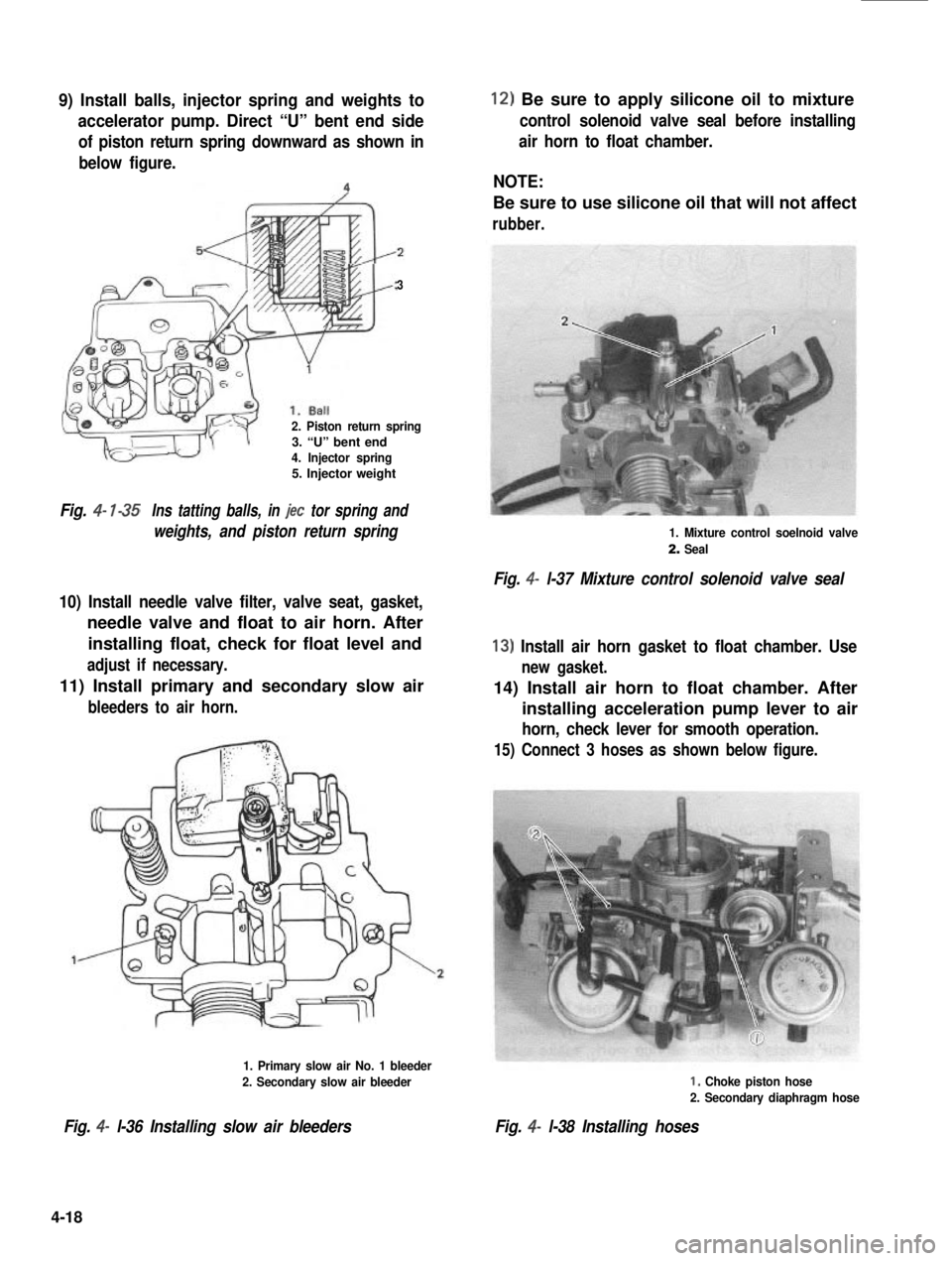
9) Install balls, injector spring and weights to
accelerator pump. Direct “U” bent end side
of piston return spring downward as shown in
below figure.
3
2. Piston return spring3. “U” bent end4. Injector spring5. Injector weight
Fig. 4- l-35Ins tatting balls, in jet tor spring and
weights, and piston return spring
10) Install needle valve filter, valve seat, gasket,
needle valve and float to air horn. After
installing float, check for float level and
adjust if necessary.
11) Install primary and secondary slow air
bleeders to air horn.
1. Primary slow air No. 1 bleeder
2. Secondary slow air bleeder
Fig. 4- l-36 Installing slow air bleeders
12) Be sure to apply silicone oil to mixture
control solenoid valve seal before installing
air horn to float chamber.
NOTE:
Be sure to use silicone oil that will not affect
rubber.
1. Mixture control soelnoid valve
2. Seal
Fig. 4- l-37 Mixture control solenoid valve seal
13) Install air horn gasket to float chamber. Use
new gasket.
14) Install air horn to float chamber. After
installing acceleration pump lever to air
horn, check lever for smooth operation.
15) Connect 3 hoses as shown below figure.
I, Choke piston hose
2. Secondary diaphragm hose
Fig. 4- l-38 Installing hoses
4-18