Page 285 of 962

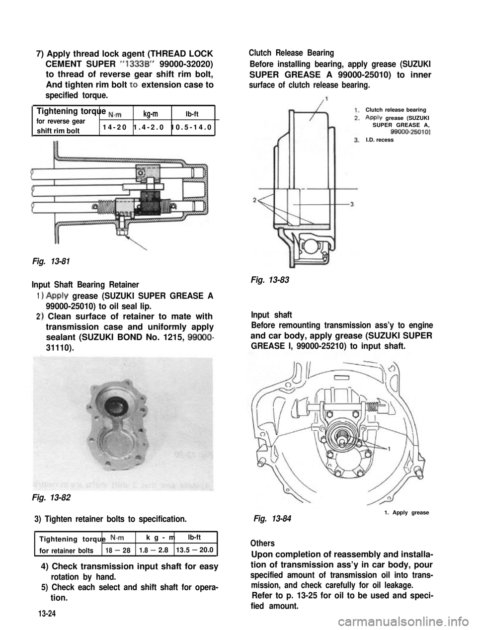
7) Apply thread lock agent (THREAD LOCK
CEMENT SUPER “1333B” 99000-32020)
to thread of reverse gear shift rim bolt,
And tighten rim bolt to. extension case to
specified torque.
Tightening torque ,,,”kg-mlb-ftfor reverse gear
shift rim bolt14-20 1.4-2.0 10.5-14.0
\
Fig. 13-81
Input Shaft Bearing Retainer
1
2
)Apply grease (SUZUKI SUPER GREASE A
99000-25010) to oil seal lip.
‘) Clean surface of retainer to mate with
transmission case and uniformly apply
sealant (SUZUKI BOND No. 1215, 99000-
31110).
Fig. 13-82
3) Tighten retainer bolts to specification.
h
Tightening torque N*mkg-mlb-ft
forretainerbolts18-281.8-2.813.5-20.0
4) Check transmission input shaft for easy
rotation by hand.
5) Check each select and shift shaft for opera-
tion.
Clutch Release Bearing
Before installing bearing, apply grease (SUZUKI
SUPER GREASE A 99000-25010) to inner
surface of clutch release bearing.
Fig. 13-83
Clutch release bearing
Apply grease (SUZUKISUPER GREASE A,99000-25010)I.D. recess
Input shaft
Before remounting transmission ass’y to engine
and car body, apply grease (SUZUKI SUPER
GREASE I, 99000-25210) to input shaft.
Fig. 13-841. Apply grease
Others
Upon completion of reassembly and installa-
tion of transmission ass’y in car body, pour
specified amount of transmission oil into trans-
mission, and check carefully for oil leakage.
Refer to p. 13-25 for oil to be used and speci-
fied amount.13-24
Page 286 of 962
13-7. MAINTENANCE SERVICES
Transmission Oil
Before changing oil, check for oil leakage first
and correct defects, if any. Fill specified new oil
in specified amount.
Oil capacity1.3 litres
(2.75/2.29 US/Imp. pt.)
IOil specificationGear oil, SAE 8OW-90,75W-80
or 75W-90I
It is. highly recommended to use SAE 75W-90.
gear oil.
For viscosity chart, refer to P. I-20.
Fig. 13-85
@ Oil filler plug
@ Oil drain plup@ Oil level plug
After filling transmission with oil, torque oil
filler and drain plugs to specification.
Tightening torque N.m
for oil drain andkg-mlb-ft
filler plug18-28 1.8-2.8 13.5-20.0
Tightening torque
for oil level pluglo-161.0-1. 7.5-11.5
NOTE:
Whenever car was hoisted for any other service
work than oil change, also be sure to check for
oil leakage.
When installing oil drain and filler plugs to
transmission case,aipply sealant (SUZUKI
BOND No.1215, 99000-31110) to thread part
of plug.
13-25
Page 299 of 962
11) When input shaft is removed, front bearing
may be left in case. In this case, after remov-
ing oil seal and circlip, bearing can be taken
out of case by using bearing installer (special
tool).
Bearing installer @ : (09913-75810)
Fig. 14-33
Transfer Rear Case
1) When center case and rear case are separated,
input shaft may be left in rear case. In this
case, remove input shaft from rear case by
hammering thick part of case with a plastic
hammer.
Fig. 14-34
14-7. INSPECTION OF COMPONENTS
Gear Teeth
Inspect gear teeth 0, internal teeth of rear
clutch sleeve @ and clutch teeth of gear 3. for
wear, cracking, chipping and other
malcondition. Replace gear or sleeve as necessary.
Fig. 14-35
Fig. 14-36
Locating Spring
Check each shifter fork shaft locating spring for
strength by measuring its free length. If length is
noted to be less than service limit, replace it.
Free length of
locating spring
14-12
Page 301 of 962
4WD Gear Shift Lever
Check lower end of gear shift lever where gear
shift fork shaft contacts @ for wear and any
kind of damage. Worn or damaged shift lever
must be replaced with new one.
14-8. REASSEMBLY
NOTE:
l All parts to be used in reassembly must be
perfectly clean.
l Oil or grease sliding and rubbing surfaces of
transfer components just before using them
in reassembly with gear oil and SUZUKI
SUPER GREASE A (99000-25010).
l Oil seals, “0” rings, gaskets and similar sealing
members must be in perfect condition. For
these members, use replacement parts in
stock.
l Tightening torque is specified for important
fasteners- mainly bolts - of transfer and
other components. Use torque wrenches and
constantly refer to specified data given in
P. 14-23.
Fig. 14-42
Input Shaft
Press-fit bearings onto both sides of input shaft
by using bearing installer (special tool).
Bearing installer (A) : (09913-84510)
(A)
Fig. 14-43
14-14
Page 308 of 962
Front Case
1) Install bearing, circlip and oil seal to front
case. Apply grease to oil seal lip and install
output front shaft using bearing installer
(special tool).
Bearing installer (A) : (09913-76010)
Fig. 14-64
2) Put gasket on center case.
3) Check front case to ensure that it is provided
with 2 dowel pins.
Fig. 14-65
4) Install front case to center case.
Fig. 14-66
5) When installing speedometer driven gear
and its gear case in rear case, apply grease to
0 ring and oil seal lip, and align bolt holes
in rear case and driven gear case.
Fig. 14-67
6) Install 4WD ball and switch. Then clamp
switch lead wire properly.
/1.6 - 2.3 kgm
Fig. 14-68 (12.0 - 16.5 lb-h)
14-21
Page 309 of 962

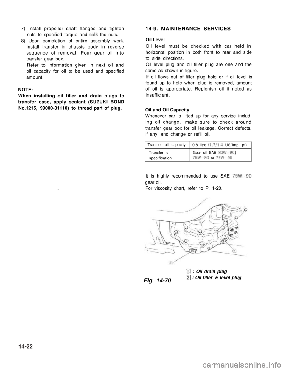
7) Install propeller shaft flanges and tighten
nuts to specified torque and talk the nuts.
8) Upon completion of entire assembly work,
install transfer in chassis body in reverse
sequence of removal. Pour gear oil into
transfer gear box.
Refer to information given in next oil and
oil capacity for oil to be used and specified
amount.
NOTE:
When installing oil filler and drain plugs to
transfer case, apply sealant (SUZUKI BOND
No.1215, 99000-31110) to thread part of plug.
14-9. MAINTENANCE SERVICES
Oil Level
Oil level must be checked with car held in
horizontal position in both front to rear and side
to side directions.
Oil level plug and oil filler plug are one and the
same as shown in figure.
If oil flows out of filler plug hole or if oil level is
found up to hole when plug is removed, amount
of oil is appropriate. Replenish oil if noted as
insufficient.
Oil and Oil Capacity
Whenever car is lifted up for any service includ-
ing oil change,make sure to check around
transfer gear box for oil leakage. Correct defects,
if any, and change or refill oil.
Transfer oil capacity0.8 litre (1.7/l .4 US/Imp. pt)
Transfer oilGear oil SAE 8OW-90,
specification75W-80 or 75W-90
It is highly recommended to use SAE 75W-90
gear oil.
For viscosity chart, refer to P. 1-20.
@ : Oil drain plug
Fig. 14-70@ : Oil filler & level plug
14-22
Page 314 of 962

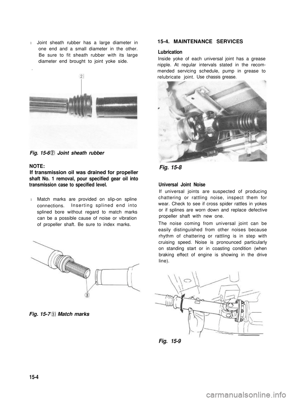
l Joint sheath rubber has a large diameter in
one end and a small diameter in the other.
Be sure to fit sheath rubber with its large
diameter end brought to joint yoke side.
.
cc
Fig. 15-6 @I Joint sheath rubber
NOTE:
If transmission oil was drained for propeller
shaft No. 1 removal, pour specified gear oil into
transmission case to specified level.
l Match marks are provided on slip-on spline
connections.Inserting splined end into
splined bore without regard to match marks
can be a possible cause of noise or vibration
of propeller shaft. Be sure to index marks.
Fig. 15-7 @I Match marks
15-4. MAINTENANCE SERVICES
Lubrication
Inside yoke of each universal joint has a grease
nipple. At regular intervals stated in the recom-
mended servicing schedule, pump in grease to
relubricate joint.Use chassis grease.
Fig. 15-8
Universal Joint Noise
If universal joints are suspected of producing
chattering or rattling noise, inspect them for
wear. Check to see if cross spider rattles in yokes
or if splines are worn down and replace defective
propeller shaft with new one.
The noise coming from universal joint can be
easily distinguished from other noises because
rhythm of chattering or rattling is in step with
cruising speed. Noise is pronounced particularly
on standing start or in coasting condition (when
braking effect of engine is showing in the drive
line).
Fig. 15-9
15-4
Page 327 of 962

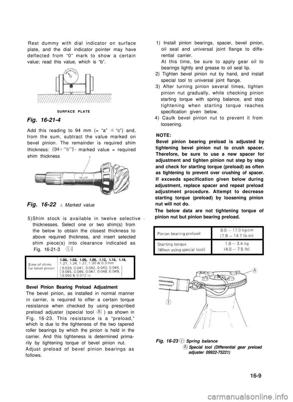
Rest dummy with dial indicator on surface
plate, and the dial indicator pointer may have
deflected from “0” mark to show a certain
value; read this value, which is “b”.
SURFACE PLATE
Fig. 16-21-4
Add this reading to 94 mm (= “a” + “c”) and,
from the sum, subtract the value marked on
bevel pinion. The remainder is required shim
thickness: (94+“b”) - marked value = required
shim thickness1
Fig. 16-22 I. Marked value
5)Shim stock is available in twelve selective L
thicknesses. Select one or two shim(s) from
the below to obtain the closest thickness to
above required thickness, and insert selected
shim piece(s) into clearance indicated as
Fig. 16-21-3 0.
1.00, 1.03, 1.06, 1.09, 1.12, 1.15, 1.18,
Bevel Pinion Bearing Preload Adjustment
The bevel pinion, as installed in normal manner
in carrier, is required to offer a certain torque
resistance when checked by using prescribed
preload adjuster (special tool @ ) as shown in
Fig. 16-23. This resistance is a “preload,”
which is due to the tighteness of the two tapered
roller bearings by which the pinion is held in the
carrier. And this tighteness is determined prima-
rily by tightening torque of bevel pinion nut.
Adjust preload of bevel pinion bearings as
follows.
1) Install pinion bearings, spacer, bevel pinion,
oil seal and universal joint flange to diffe-
rential carrier.
At this time, be sure to apply gear oil to
bearings lightly and grease to oil seal lip.
2) Tighten bevel pinion nut by hand, and install
special tool to universal joint flange.
3) After turning pinion several times, tighten
pinion nut gradually, while checking pinion
starting torque with spring balance, and stop
tightening when starting torque reaches
specification given below.
4) Caulk bevel pinion nut to prevent it from
loosening.
NOTE:
Bevel pinion bearing preload is adjusted by
tightening bevel pinion nut to crush spacer.
Therefore, be sure to use a new spacer for
adjustment and tighten pinion nut step by step
and check for starting torque (preload) as often
as tightening to prevent over crushing of spacer.
If exceeds specification given below during
adjustment, replace spacer and repeat preload
adjustment procedure. Attempt to decrease
starting torque (preload) by loosening pinion
nut will not do.
The below data are not tightening torque of
pinion nut but pinion bearing preload.
Fig. 16-23 @ Spring balance
@ Special tool (Differential gear preload
adjuster 09922-75221)
16-9