Page 372 of 962
18-5. INSPECTION OF COMPONENTS
Steering Gear Box
[Oil level]
Oil surface should be up to the level as shown
in below figures. If not, add prescribed gear oil,
SAE 90.
Right hand steering vehicle
Fig. 18-17
Left hand steering vehicle
I
35mm(1.4 in.)
Fig. 18-18
[Adjustment of worm shaft starting torque]
The steering gear box is provided with adjust-
ing bolt @ which gives preload to sector shaft.
Fig. 18-19 (1)Adjusting bolt
Make an adjustment according to the following
procedure.
1) Check worm shaft to ensure that it is free
from thrust play.
2) Position pitman arm in parallel with worm
shaft as shown below.
(With pitman arm in this position, front
wheel is in straightforward state.)
Worm shaft
Fig. 18-20
Pitman arm
18-9
Page 382 of 962

Steering Gear Box
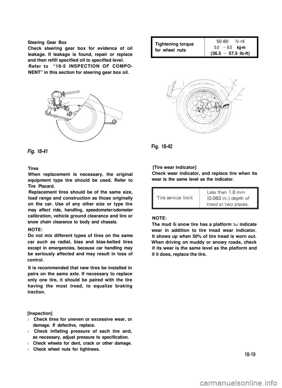
Check steering gear box for evidence of oil
leakage. If leakage is found, repair or replace
and then refill specified oil to specified level.
Refer to“18-5 INSPECTION OF COMPO-
NENT” in this section for steering gear box oil.
Tightening torque
for wheel nuts
50-80 N.m
5.0 - 8.0 kg-m
(36.5 - 57.5 lb-ft)
Fig. 18-42
Fig. 18-41
Tires[Tire wear indicator]
When replacement is necessary, the original
equipment type tire should be used. Refer to
Tire Placard.
Check wear indicator, and replace tire when its
wear is the same level as the indicator.
Replacement tires should be of the same size,
load range and construction as those originally
on the car. Use of any other size or type tire
may affect ride, handling, speedometer/odometer
calibration, vehicle ground clearance and tire or
snow chain clearance to body and chassis.
NOTE:
NOTE:
Do not mix different types of tires on the same
car such as radial, bias and bias-belted tires
except in emergencies, because car handling may
be seriously affected and may result in loss of
control.
The mud & snow tire has a platform ttr indicate
wear in addition to tire tread wear indicator.
It shows up when 50% of tire tread is worn out.
When driving on muddy or snowy roads, check
if its wear is the same level as the platform and
if it does, replace the tire.
It is recommended that new tires be installed in
pairs on the same axle. If necessary to replace
only one tire, it should be paired with the tire
having the most tread, to equalize braking
traction.
[Inspection]
l Check tires for uneven or excessive wear, or
damage. If defective, replace.
l Check inflating pressure of each tire and,
as necessary, adjust pressure to specification.
l Check wheels for dent, crack or other damage.
l Check wheel nuts for tightness.
18-19
Page 396 of 962
![SUZUKI GRAND VITARA 1987 Service Repair Manual BOOSTER ASSEMBLY
[GENERAL DESCRIPTION]
The booster is located between the master cylinder and the brake pedal. It is so designed that the force
created when the brake pedal is depressed is mechanicall SUZUKI GRAND VITARA 1987 Service Repair Manual BOOSTER ASSEMBLY
[GENERAL DESCRIPTION]
The booster is located between the master cylinder and the brake pedal. It is so designed that the force
created when the brake pedal is depressed is mechanicall](/manual-img/20/57437/w960_57437-395.png)
BOOSTER ASSEMBLY
[GENERAL DESCRIPTION]
The booster is located between the master cylinder and the brake pedal. It is so designed that the force
created when the brake pedal is depressed is mechanically increased combined with the engine vacuum.
The booster has a diaphragm of 4 180 mm effective diameter. Its operation is described in the following pages.
NOTE:
Use all components included in repair kits to service this booster. Lubricate rubber parts, where indicat-
ed, with silicone grease provided in kits. The torque values specified are for dry, unlubricated fasteners.
If any hydraulic component is removed or brake line disconnected, bleed the brake system.
Never lubricate any hydraulic component with silicone grease.
11.Vacuum check valve11.No. 2 body oil seal
2.3.Grommet12.Booster air valve assembly
Booster No. 1 body13.Air cleanerseparator
4. PistonRod14.Air cleaner element
5. Reaction disc 15.Body boot
6.Booster piston returnspring16.Nut7. Valve stopper key17.Bracket
8.Booster piston18.Push rod clevis
9. Diaphragm19.Pressure plate
10.Booster No. 2 body
Fig. 19-12
19-11
Page 404 of 962

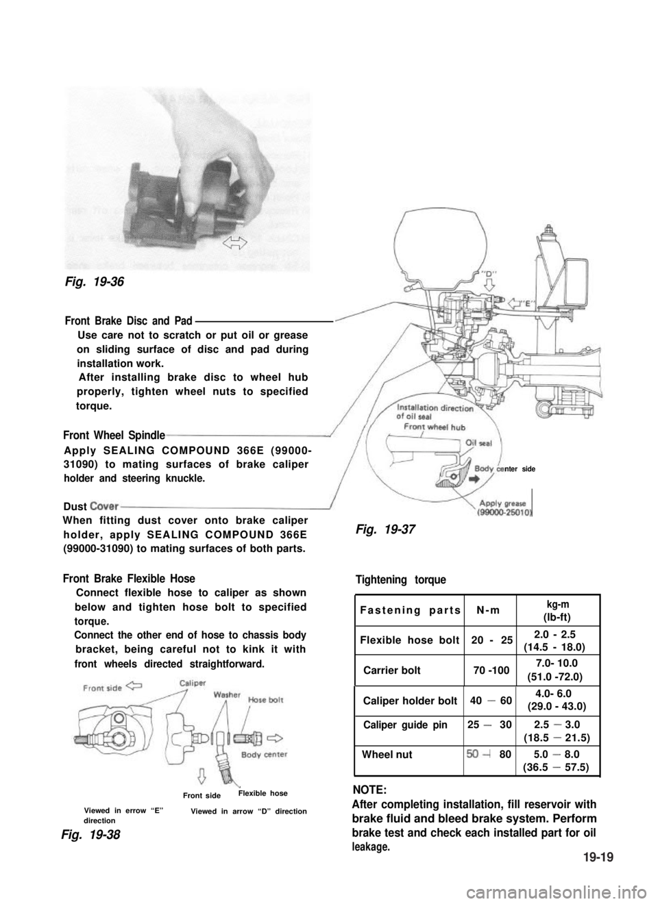
Fig. 19-36
Front Brake Disc and Pad
Use care not to scratch or put oil or grease
on sliding surface of disc and pad during
installation work.
After installing brake disc to wheel hub
properly, tighten wheel nuts to specified
torque.
Front Wheel Spindle
Apply SEALING COMPOUND 366E (99000-
31090) to mating surfaces of brake caliper
holder and steering knuckle.nter side
Dust Cover/
When fitting dust cover onto brake caliper
holder, apply SEALING COMPOUND 366E
(99000-31090) to mating surfaces of both parts.
Front Brake Flexible Hose
Connect flexible hose to caliper as shown
below and tighten hose bolt to specified
torque.
Connect the other end of hose to chassis body
bracket, being careful not to kink it with
front wheels directed straightforward.
\Front sideFlexible hose
Viewed in errow “E”Viewed in arrow “D” directiondirection
Fig. 19-38
V(gg!&
Fig. 19-37
Tightening torque
Fastening parts N-mkg-m
(lb-ft)
Flexible hose bolt 20 - 252.0 - 2.5
(14.5 -18.0)
Carrier bolt 70 -100
Caliper holder bolt 40 -60
Caliper guide pin25 -302.5-3.0
(18.5-21.5)
Wheel nut50-805.0-8.0
(36.5-57.5)
NOTE:
After completing installation, fill reservoir with
brake fluid and bleed brake system. Perform
brake test and check each installed part for oil
leakage.
(51.0 -72.0)
7.0- 10.0
4.0- 6.0
(29.0 - 43.0)
19-19
Page 407 of 962
Brake Shoe and Rim
If lining is worn out beyond service limit,
replace shoe.
Brake
liningStandardService
limit
Thickness
(lining +
shoe rim)
7.0 mm3.0 mm
(0.28 in.)(0.12 in.)
Wheel Cylinder
When removing brake drum, check wheel
cylinder for oil leakage. If any leakage is found,
replace wheel cylinder inner parts.
Inspect wheel cylinder disassembled parts for
wear, cracks, corrosion or damage.
NOTE:
Clean wheel cylinder components with brake
fluid.
Fig. 19-46
Fig. 19-45
If one of brake linings is worn to or beyond
service limit, all linings must be replaced at the
same time.
NOTE:
Never polish lining with sandpaper. If lining is
polished with sandpaper, hard particles of sand-
paper will be deposited in lining and may
damage drum. When it is required to correct
lining, replace it with a new one.
Brake Strut
Inspect ratchet of strut for wear or damage.
Fig. 19-47
19-22
Page 411 of 962
4) Before installing brake drum, to maximize
brake shoe-todrum clearance, put screw
driver between rod and ratchet and push
down ratchet as shown in figure.
\
2. Ratchet
3. Driver
Below figure shows ratchet positionwhere brake shoe-to-drum clearanceis maximum.
Fig. 19-54
5) Install brake drum after making sure that
inside of brake drum and brake shoes are free
from dirt and oil.
6) Torque wheel nuts and brake drum nuts to
specification.
NOTE:
If brake backing plate was removed from wheel
cylinder or brake pipe was disconnected from
wheel cylinder. Bleed air from brake system.
(For bleeding operation, refer to p. 19-46.)
7) Upon completion of all jobs, depress brake
pedal with about 30 kg (66 Ibs) load four or
five times so as to obtain proper drum-to-
shoe clearance.
8) Check to ensure that brake drum is free from
dragging and proper braking is obtained. Then
remove car from hoist and perform brake test
(foot brake and parking brake).
Fig. 19-55
19-26
Page 415 of 962
19-5. BRAKE BOOSTERDISASSEMBLY
REMOVAL
1) Take out fluid from master cylinder with a
syringe or such.
2) Disconnect 2 brake pipes from master cylinder
and remove master cylinder from booster.
3) Disconnect vacuum hose from booster.
4) Disconnect push rod clevis from brake pedal
arm.
5) Remove attaching nuts and then booster as
shown.
Vacuum hose
2.Booster3. Push rod clevis
4.Dash panel5.Attaching nuts6.Master cylinder
7.Gasket
8. Split pin
9. Master cylinder pin
10. Gasket11 Attaching nuts
Fig. 19-65
49
-@P
Iii
1. Vacuum check valve
2. Grommet3. Booster No. 1 body4. Piston rod
5. Reaction disc6. Booster piston return
spring7. Valve stopper key8. Booster piston9. Booster air valve assembly10. Pressure plate
Fig. 19-66
11.Diaphragm12.Booster No. 2body
13.No. 2 body oilseal14. Air cleaner separator15. Air cleaner element
16.Body bootNut
18.Bracket
19. Push rod clevis
1) Remove piston rod from booster.
2) Remove push rod clevis and nut.
Fig. 19-67
19-30
1.
17.
Page 420 of 962

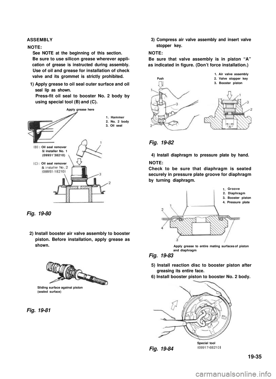
ASSEMBLY
NOTE:
See NOTE at the beginning of this section.
Be sure to use silicon grease wherever appli-
cation of grease is instructed during assembly.
Use of oil and grease for installation of check
valve and its grommet is strictly prohibited.
1) Apply grease to oil seal outer surface and oil
seal lip as shown.
Press-fit oil seal to booster No. 2 body by
using special tool (B) and (C).
Apply grease here
1. Hammer2. No. 2 body3. Oil seal
(6) : Oil seal remover& installer No. 1(09951’38210)
Oil seal remover
Fig. 19-80
2) Install booster air valve assembly to booster
piston. Before installation, apply grease as
shown.
Sliding surface against piston(sealed surface)
Fig. 19-81
3) Compress air valve assembly and insert valve
stopper key.
NOTE:
Be sure that valve assembly is in piston “A”
as indicated in figure. (Don’t force installation.)
Push
n
1. Air valve assembly2. Valve stopper key3. Booster piston
Fig. 19-82
4) Install diaphragm to pressure plate by hand.
NOTE:
Check to be sure that diaphragm is seated
securely in pressure plate groove for diaphragm
by turning diaphragm.
Groove2. Diaphragm
3. Booster piston4. Pressure plate
Apply grease to entire mating surfacesof pistonand diaphragm
Fig. 19-83
5) Install reaction disc to booster piston after
greasing its entire face.
6) Install booster piston to booster No. 2 body.
Fig. 19-84
Special tool
(09917-682101
19-35
1.