1987 SUZUKI GRAND VITARA check oil
[x] Cancel search: check oilPage 149 of 962
![SUZUKI GRAND VITARA 1987 Service Repair Manual ,Fuel Pump
[ Rem’oval]
1) Disconnect negative cable from battery.
2) Remove fuel filler cap from fuel filler neck to
release fuel vapor pressure in fuel tank. After
releasing, reinstall the cap.
3) SUZUKI GRAND VITARA 1987 Service Repair Manual ,Fuel Pump
[ Rem’oval]
1) Disconnect negative cable from battery.
2) Remove fuel filler cap from fuel filler neck to
release fuel vapor pressure in fuel tank. After
releasing, reinstall the cap.
3)](/manual-img/20/57437/w960_57437-148.png)
,Fuel Pump
[ Rem’oval]
1) Disconnect negative cable from battery.
2) Remove fuel filler cap from fuel filler neck to
release fuel vapor pressure in fuel tank. After
releasing, reinstall the cap.
3) Disconnect fuel inlet, outlet and return hoses
from fuel pump.
Fuel Filter
[Removal]
1) Disconnect negative cable from battery.
2) Remove fuel filler cap to release fuel vapor
pressure in fuel tank. After releasing, reinstall
the cap.
3) Disconnect inlet and outlet hoses from fuel
filter.
4) Remove fuel filter with clamp.
[Installation]
1) Install filter and clamp, and connect inlet
and outlet hoses to fuel filter.
NOTE:.
The top connection is for outlet hose, the
lower one for inlet hose.
1. Fuel pump
2. Inlet hose3. Outlet hose
4. Return hose
Fig. 4-2-l 1
4) Remove fuel pump from cylinder head.
5) Remove fuel pump rod from cylinder head.
2
1. Fuel pump rod
2. Cylinder head
[Installation]
Reverse removal procedure for installation
using care for the following.
l After oiling it,install fuel pump rod to
cylinder head.
0 Use new fuel pump gasket.
l Make sure for proper hose connection.
0 Upon completion of installation, start engine
and check fuel hose or its joints for leaks.
1.Fuel filter3.From fueltank
2.To fuel pump4.Clamp
Fig.4-2-13
2) Connect negative cable to battery.
3) After installation, start engine and check it
for leaks.
Fuel Tank
[Removal]
1) Disconnect negative cable from battery.
2) Disconnect fuel level gauge lead wire.
3) To release the pressure in fuel tank, remove
fuel filler cap and then, reinstall it.
4) Raise car on hoist.
5) Drain fuel by removing drain plug.
6) Remove filler hose protector.
7) Disconnect filler hose from fuel tank.
.8) Disconnect fuel hosesand pipe from fuel tank.
9) Remove fuel tank.
4-34
Page 168 of 962
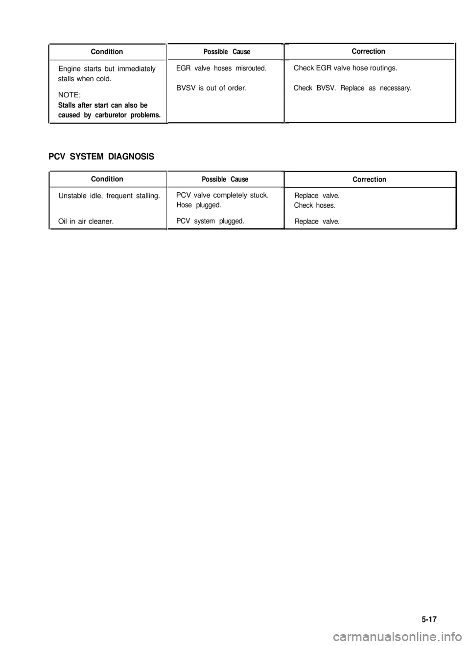
Condition
Engine starts but immediately
stalls when cold.
NOTE:
Stalls after start can also be
caused by carburetor problems.
PCV SYSTEM DIAGNOSIS
Condition
Unstable idle, frequent stalling.
Oil in air cleaner.
Possible Cause
EGR valve hoses misrouted.
BVSV is out of order.
Possible Cause
PCV valve completely stuck.
Hose plugged.
PCV system plugged.
Correction
Check EGR valve hose routings.
Check BVSV. Replace as necessary.
Correction
Replace valve.
Check hoses.
Replace valve.
5-17
Page 182 of 962
![SUZUKI GRAND VITARA 1987 Service Repair Manual [Checking ECM power circuits]
Connected to the ECM are the ignition coil and solenoids or solenoid valves. If a disconnection or a
failure of contact occurs within a circuit (power circuit) including SUZUKI GRAND VITARA 1987 Service Repair Manual [Checking ECM power circuits]
Connected to the ECM are the ignition coil and solenoids or solenoid valves. If a disconnection or a
failure of contact occurs within a circuit (power circuit) including](/manual-img/20/57437/w960_57437-181.png)
[Checking ECM power circuits]
Connected to the ECM are the ignition coil and solenoids or solenoid valves. If a disconnection or a
failure of contact occurs within a circuit (power circuit) including any of these coil or solenoids or sole-
noid valves, signals will not be sent to the ECM and as a result, the feed back system will not operate
properly. Therefore, check the power circuits according to the following procedure.
1) Disconnect the coupler connected to the ECM.
2) Turn ON the ignition switch but be sure not to run the engine.
3) Connect a voltmeter between the terminal @ of the disconnected coupler (on the wiring harness side)
and the body (ground) as shown in below figure and measure the voltage. And then repeat the same
with each of the terminals 0, 0, 0, 0, 8, @ and 0. If the measured voltage between each
terminal and the body is about 12V, each circuit is in good condition.
4) If about 12V is not obtained in the above check, the particular circuit may be disconnected or out of
contact. Check the circuit for such conditions.
5) After checking, connect the coupler to ECM securely..
1. Coupler (Viewed from wire harness side)10. Three way solenoid valve (EGR system)
2. Battery11. Br (Brown) lead wire
3. Ignition switch (ON)!2. BI/R (Blue/Red) lead wire
4. Ignition coil13. B/W (Black/White) lead wire
5. Vacuum switching valve14. Br/W (Brown/White) lead wire(secondary throttle valve)15. BI/B (Blue/Black) lead wire6. Three way solenoid valve (Idle-up)16. BI/Y (Blue/Yellow) lead wire7. Mixture control solenoid17. BI/W (Blue/White) lead wire8. Switch vent solenoid18. BllG (Blue/Green) lead wire9. Fuel cut solenoid valve
Fig. 5-3-42 Checking ECM power circuits
Page 193 of 962
Radiator Cap
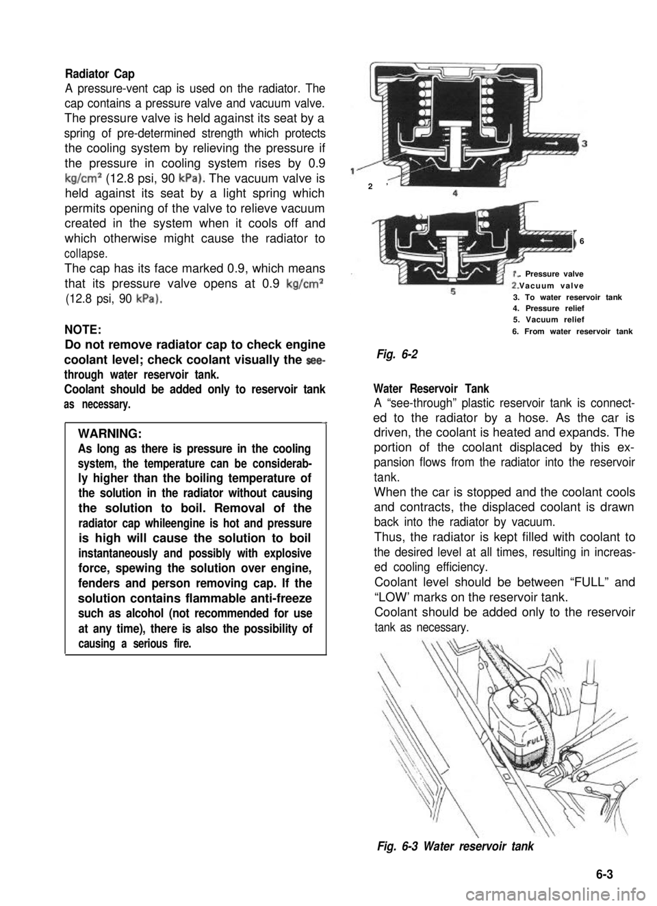
A pressure-vent cap is used on the radiator. The
cap contains a pressure valve and vacuum valve.
The pressure valve is held against its seat by a
spring of pre-determined strength which protects
the cooling system by relieving the pressure if
the pressure in cooling system rises by 0.9
kg/cm2 (12.8 psi, 90 kPa). The vacuum valve is
held against its seat by a light spring which
permits opening of the valve to relieve vacuum
created in the system when it cools off and
which otherwise might cause the radiator to
collapse.
The cap has its face marked 0.9, which means
that its pressure valve opens at 0.9 kg/cm2
(12.8 psi, 90 kPa).
NOTE:
Do not remove radiator cap to check engine
coolant level; check coolant visually the see-
through water reservoir tank.
Coolant should be added only to reservoir tank
as necessary.
4
WARNING:
As long as there is pressure in the cooling
system, the temperature can be considerab-
ly higher than the boiling temperature of
the solution in the radiator without causing
the solution to boil. Removal of the
radiator cap whileengine is hot and pressure
is high will cause the solution to boil
instantaneously and possibly with explosive
force, spewing the solution over engine,
fenders and person removing cap. If the
solution contains flammable anti-freeze
such as alcohol (not recommended for use
at any time), there is also the possibility of
causing a serious fire.
2’
I6
. Pressure valve
Vacuum valve
3. To water reservoir tank4. Pressure relief5. Vacuum relief
6. From water reservoir tank
Fig. 6-2
Water Reservoir Tank
A “see-through” plastic reservoir tank is connect-
ed to the radiator by a hose. As the car is
driven, the coolant is heated and expands. The
portion of the coolant displaced by this ex-
pansion flows from the radiator into the reservoir
tank.
When the car is stopped and the coolant cools
and contracts, the displaced coolant is drawn
back into the radiator by vacuum.
Thus, the radiator is kept filled with coolant to
the desired level at all times, resulting in increas-
ed cooling efficiency.
Coolant level should be between “FULL” and
“LOW’ marks on the reservoir tank.
Coolant should be added only to the reservoir
tank as necessary.
Fig. 6-3 Water reservoir tank
6-3
Page 201 of 962
Coolant
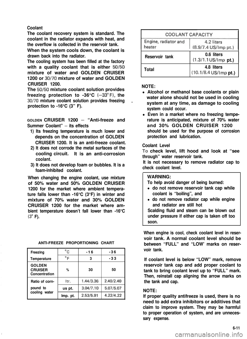
The coolant recovery system is standard. The
coolant in the radiator expands with heat, and
the overflow is collected in the reservoir tank.
When the system cools down, the coolant is
drawn back into the radiator.
The cooling system has been filled at the factory
with a quality coolant that is either 50/50
mixture of water and GOLDEN CRUISER
1200 or 30/70 mixture of water and GOLDEN
CRUISER 1200.
The 50/50 mixture coolant solution provides
freezing protection to -36°C (-33”F), the
30/70 mixture coolant solution provides freezing.
protection to -16°C (3” F).
GOLDEN CRUISER 1200 - “Anti-freeze and
Summer Coolant” - its effects
1) Its freezing temperature is much lower and
depends on the concentration of GOLDEN
CRUISER 1200. It is an anti-freeze coolant.
2) It does not corrode the metal surfaces of the
cooling circuit.It is an anti-corrosion
coolant.
3) It does not develop foam or bubbles. It is a
foam-inhibited coolant.
When changing the engine coolant, use mixture
of 50% water and 50% GOLDEN CRUISER
1200 for the market where ambient tempera-
ture falls lower than -16°C (3°F) in winter and
mixture of 70% water and 30% GOLDEN
CRUISER 1200 for the market where am-
bient temperature doesn’t fall lower than -16°C
(3” F).
ANTI-FREEZE PROPORTIONING CHART
Freezing
Temperature
GOLDEN
CRUISERConcentration
OC-16-36
OF3-33
%3050
Ratio of corn-Itr.1.4413.362.4012.40
pound tous pt.3.04l7.10 5.0715.07cooling waterImp. pt.2.5315.914.221422
Reservoir tank0.6 liters
(1.3/1.1 US/Imp pt.)I
Total4.8 liters
(10.1/8.4 US/Imp pt.)
NOTE:
l Alcohol or methanol base coolants or plain
water alone should not be used in cooling
system at any time, as damage to cooling
system could occur.
l Even in a market where no freezing tempe-
rature is anticipated, mixture of 70% water
and 30% GOLDEN CRUISER 1200
should be used for the purpose of corrosion
protection and lubrication.
Coolant Level
,To check level, lift hood and look at “see
through” water reservoir tank.
It is not necessary to remove radiator cap to
check coolant level.
WARNING:
To help avoid danger of being burned:
l do not remove reservoir tank cap while
coolant is “boiling”, and
l do not remove radiator cap while engine
and radiator are still hot
Scalding fluid and steam can be blown out
under pressure if either cap is taken off too
soon.
When engine is cool, check coolant level in reser-
voir tank. A normal coolant level should be
between “FULL” and “LOW’ marks on reser-
voir tank.
If coolant level is below “LOW” mark, remove
reservoir tank cap and add proper coolant to
tank to bring coolant level up to “FULL” mark.
Then, reinstall cap aligning the arrow marks on
the tank and cap.
NOTE:
If proper quality antifreeze is used, there is no
need to add extra inhibitors or additives that
claim to improve system. They may be harmful
to proper operation of system, and are unneces-
sary expense.
6-11
Page 212 of 962
8-l. GENERAL DESCRIPTION
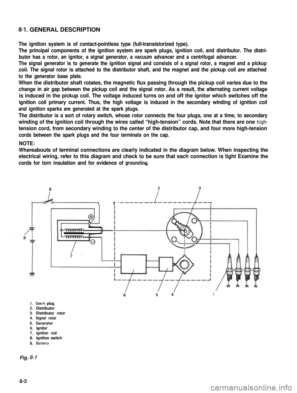
The ignition system is of contact-pointless type (full-transistorized type).
The principal components of the ignition system are spark plugs, ignition coil, and distributor. The distri-
butor has a rotor, an ignitor, a signal generator, a vacuum advancer and a centrifugal advancer.
The signal generator is to generate the ignition signal and consists of a signal rotor, a magnet and a pickup
coil. The signal rotor is attached to the distributor shaft, and the magnet and the pickup coil are attached
to the generator base plate.
When the distributor shaft rotates, the magnetic flux passing through the pickup coil varies due to the
change in air gap between the pickup coil and the signal rotor. As a result, the alternating current voltage
is induced in the pickup coil. The voltage induced turns on and off the ignitor which switches off the
ignition coil primary current. Thus, the high voltage is induced in the secondary winding of ignition coil
and ignition sparks are generated at the spark plugs.
The distributor is a sort of rotary switch, whose rotor connects the four plugs, one at a time, to secondary
winding of the ignition coil through the wires called “high-tension” cords. Note that there are one high-
tension cord, from secondary winding to the center of the distributor cap, and four more high-tension
cords between the spark plugs and the four terminals on the cap.
NOTE:
Whereabouts of terminal connections are clearly indicated in the diagram below. When inspecting the
electrical wiring, refer to this diagram and check to be sure that each connection is tight Examine the
cords for torn insulation and for evidence of groundinq
8
r
6541
1.Spark plug2.Distributor3.Distributor rotor4.Signal rotor
5.Generator6.lgnitor7.Ignition coil8.Ignition switch
9.Battery
Fig. 8- 1
8-2
Page 215 of 962
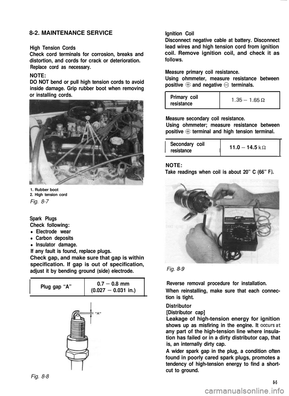
8-2. MAINTENANCE SERVICEIgnition Coil
High Tension Cords
Check cord terminals for corrosion, breaks and
distortion, and cords for crack or deterioration.
Replace cord as necessary.
NOTE:
DO NOT bend or pull high tension cords to avoid
inside damage. Grip rubber boot when removing
orinstalling cords.
1. Rubber boot2. High tension cord
Fig. 8-7
Spark Plugs
Check following:
l Electrode wear
l Carbon deposits
l Insulator damage.
If any fault is found, replace plugs.
Check gap, and make sure that gap is within
specification. If gap is out of specification,
adjust it by bending ground (side) electrode.
I
Plug gap “A”0.7 - 0.8 mm
(0.027 - 0.031 in.)
Disconnect negative cable at battery. Disconnect
lead wires and high tension cord from ignition
coil. Remove ignition coil, and check it as
follows.
Measure primary coil resistance.
Using ohmmeter, measure resistance between
positive @ and negative @ terminals.
Primary coil
resistance1.35- 1.65D
Measure secondary coil resistance.
Using ohmmeter; measure resistance between
positive @ terminal and high tension terminal.
I
Secondary coil
resistanceI11.0 - 14.5 kSZ
I
NOTE:
Take readings when coil is about 20” C (66” F).
Fig. &9
Reverse removal procedure for installation.
When reinstalling, make sure that each connec-
tion is tight.
Distributor
[Distributor cap]
Leakage of high-tension energy for ignition
shows up as misfiring in the engine. It occursat
any part of the high-tension line where insula-
tion has failed or in a dirty distributor cap, that
is, an internally dirty cap.
A wider spark gap in the plug, a condition often
found in poorly cared spark plugs, promotes a
tendency of high-tension energy to find a short-
cut to ground.
Fig. 8-8
8-5
Page 217 of 962
I
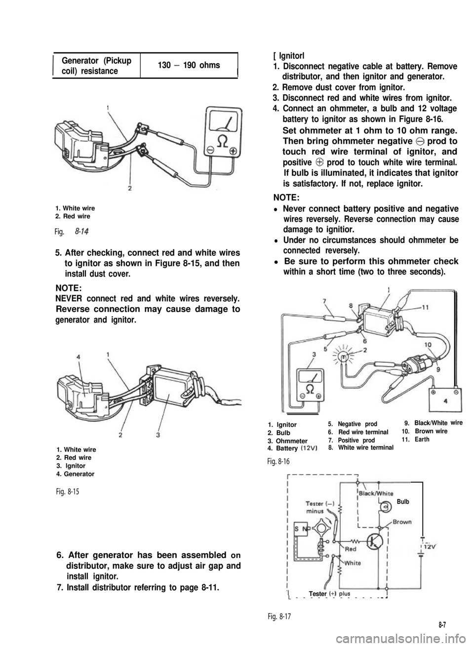
Generator (Pickup
coil) resistance130 - 190 ohmsI
1
1. White wire2. Red wire
Fig. 8-14
5. After checking, connect red and white wires
to ignitor as shown in Figure 8-15, and then
install dust cover.
NOTE:
NEVER connect red and white wires reversely.
Reverse connection may cause damage to
generator and ignitor.
1. White wire2. Red wire
3. lgnitor
4. Generator
Fig. 8-15
6. After generator has been assembled on
distributor, make sure to adjust air gap and
install ignitor.
7. Install distributor referring to page 8-11.
[ Ignitorl
1. Disconnect negative cable at battery. Remove
distributor, and then ignitor and generator.
2. Remove dust cover from ignitor.
3. Disconnect red and white wires from ignitor.
4. Connect an ohmmeter, a bulb and 12 voltage
battery to ignitor as shown in Figure 8-16.
Set ohmmeter at 1 ohm to 10 ohm range.
Then bring ohmmeter negative @ prod to
touch red wire terminal of ignitor, and
positive @ prod to touch white wire terminal.
If bulb is illuminated, it indicates that ignitor
is satisfactory. If not, replace ignitor.
NOTE:
l Never connect battery positive and negative
wires reversely. Reverse connection may cause
damage to ignitior.
l Under no circumstances should ohmmeter be
connected reversely.
l Be sure to perform this ohmmeter check
within a short time (two to three seconds).
1
1. lgnitor5.Negative prod9.Black/Whitewire
2. Bulb6.Red wire terminal10.Brown wire
3. Ohmmeter7.Positive prod11.Earth
4. Battery (12V)8.White wire terminal
Fig. 8-16
c---------~
Bulb
T_-.
ITester (+) PIUSL------------
Fig. 8-17
8-7