Page 220 of 962
![SUZUKI GRAND VITARA 1987 Service Repair Manual [Checking vacuum advancer]
Remove distributor cap.
Disconnect vacuum hose from vacuum hose 3
way joint, and connect vacuum pump gauge
(0991747910) to its hose. Apply vacuum (ab-
out 400 mmHg). And the SUZUKI GRAND VITARA 1987 Service Repair Manual [Checking vacuum advancer]
Remove distributor cap.
Disconnect vacuum hose from vacuum hose 3
way joint, and connect vacuum pump gauge
(0991747910) to its hose. Apply vacuum (ab-
out 400 mmHg). And the](/manual-img/20/57437/w960_57437-219.png)
[Checking vacuum advancer]
Remove distributor cap.
Disconnect vacuum hose from vacuum hose 3
way joint, and connect vacuum pump gauge
(0991747910) to its hose. Apply vacuum (ab-
out 400 mmHg). And then with pump stopped,
check to ensure that vacuum pump gauge
indicator remains at the same level, and release
it. Check that generator base plate with gene-
rator moves smoothly. If plate does not move
smoothly, replace defective parts.
Fig. 8-24
1. Distributor drive gear
2. Camshaft3. Cylinder head
Fig. 8-23
@I Vacuum pump gauge (a991 7-47910)
1. Generator base plate
2. Vacuum controller
Distributor Drive Gear
NOTE:
When removing distributor gear case from cylin-
der head, engine oil in cylinder head may come
out. So place waste or receiver under gear case
when removing.
Inspect drive gear for wear.
Worn gear is likely to disturb ignition timing
and therefore must be replaced.
Replacing worn-down drive gear is not enough.
Inspect driven gear (a part of the distributor
assembly), too, and replace it if badly worn
down.
[Important reminders for removal and installa-
tion]
Before removing drive gear from camshaft,
scribe a match mark on this shaft to root
center line of drive gear as shown in Fig.
B-25 and, when mounting replacement drive
gear, refer to this mark.
When pressing replacement drive gear onto
camshaft, be sure to position gear angularly
as shown in Fig. B-25. (align mark on Cam-
shaft scribed in removal with root center of
drive gear)
NOTE:
There is no need to discriminate between two
end faces of drive gear.
Distributor side view
1. Drive gear
2. Camshaft
3. Center line of
45mmhole
4. Center line ofroot5. @5mm hole(Provided on pulleyside of camshaft)
6. Scribed matchmark
7. 5O
Fig. 8-25
l About 30 cc(1.01/l .05 US/Imp 02) of
engine oil must be fed into distributor gear
case after servicing this case, that is, removing
and putting it back. Be sure to add this much
oil before starting engine for the first time
after servicing.
8-11
Page 229 of 962
Ground test
Check commutator and armature coil core. If
there is continuity, armature is grounded and
must be replaced.
Fig. 915
Open circuit test
Check for continuity between segments. If
there is no continuity at any test point, there is
an open circuit and armature must be replaced.
Fig. 9 16
2) Inspect Field Coil
Open circuit test
Check for continuity between brush and bare
surface. If there is continuity, field windings are
grounded. The field coil must be replaced.
Fig. 917
3) Inspect Brush
Check brushes for wear. If below limit, replace
brush.
Brush length~~
Fig. 918
9-8
Page 231 of 962
8) Inspect Magnetic SwitchHold in coil open circuit test
Push in plunger and release it. The plungerCheck for continuity across magnetic switch ‘S’
should return quickly to its original position.terminal and coil case. If no continuity exists,
Replace if necessary.the coil is open and should be replaced.
Fig. 925
Pull-in coil open circuit test
Check for continuity across magnetic switch
‘s’ terminal and ‘M’ terminal. If no continuity
exists, the coil is open and should be replaced.
Fig. 926
Fig. 927
REASSEMBLY
Reverse disassembly procedure, using care on
following points.
l When installing pinion drive lever, refer to
Fig. g-2 for its installation direction.
0. When installing brush holder, be careful of
brush position.
2
3
1. Brush holder
2. Yoke
3. Brush positions
Fig. 9-27- 1
9-10
Page 232 of 962
9-7. PERFORMANCE TEST
IMPORTANT:
These tests must be performed within 3 -
5 seconds to avoid burning out the coil.
3) Check Plunger Return
Disconnect negative lead from switch body.
Check that plunger returns inward.
If plunger does not return, replace magnetic
switch.
1) Pull-in Test
Connect battery to magnetic switch as shown.
Check that plunger moves outward.
If plunger does not move, replace magnetic
switch.
Fig.
Before’testing,disconnect fieldcoil lead fromterminal M
w
9-28
2) Hold-in Test
While connected as above with plunger out,
disconnect negative lead from terminal M.
Check that plunger remains out.
If plunger returns inward, replace magnetic
switch. ’
Fig. 930
4) No-load Performance Test
a)Connect battery and ammeter to starter as
shown.
b) Check that starter rotates smoothly and
steadily with pinion moving out. Check that
ammeter reads the specified current.
Specified current
Less than 60 A at 11.5 V
Fig. 931
Fig. 929
9-11
Page 241 of 962
INSPECTIONStator
Rotor
1) Check rotor for no open circuits
Using an ohmmeter, check for continuity
between slip rings.
Fig. lo-12
Standard resistance2.8 - 3.0 !aI
If there is no continuity, replace rotor.
2) Check rotor for no grounds.
Using an ohmmeter, check that there is no
continuity between slip ring and rotor.
If there is continuity, replace rotor.
Fig. 10-13
1) Check stator for no open circuits
Using an ohmmeter, check all leads for con-
tinuity. If there is no continuity, replace
stator.
Fig. 1014
2) Check stator for no grounds
Using an ohmmeter, check that there is no
continuity between coil leads and stator core.
If there is continuity, replace rotor.
Fig. 1015
3) Inspect slip rings
Check slip rings for roughness or scoring. If
rough or scored, replace rotor.
10-8
Page 265 of 962

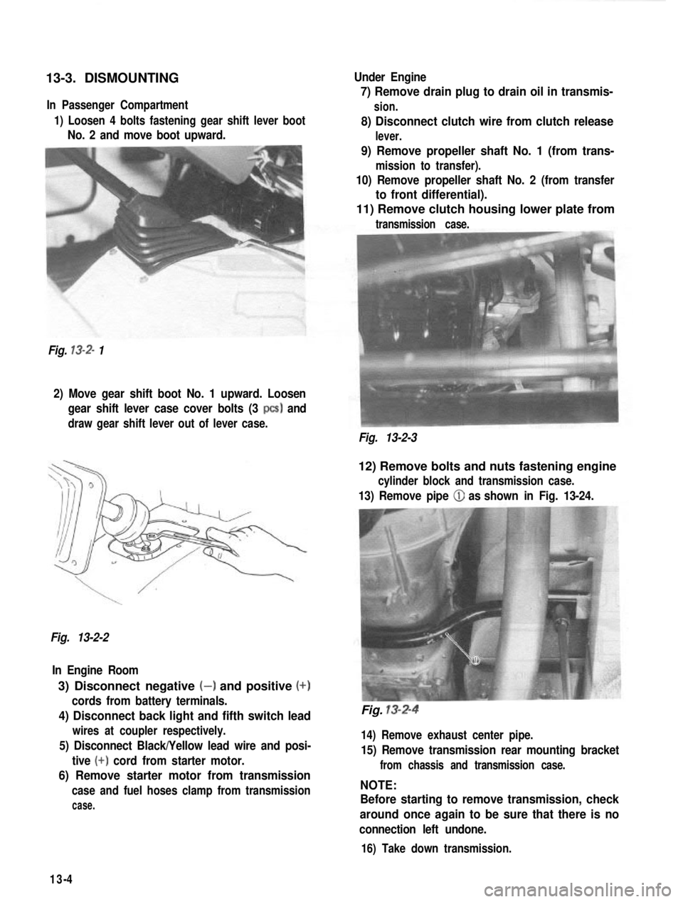
13-3. DISMOUNTINGIn Passenger Compartment
1) Loosen 4 bolts fastening gear shift lever boot
No. 2 and move boot upward.
Fig.
13-2- 1 Under Engine
7) Remove drain plug to drain oil in transmis-
sion.
8) Disconnect clutch wire from clutch release
lever.
9) Remove propeller shaft No. 1 (from trans-
mission to transfer).
10) Remove propeller shaft No. 2 (from transfer
to front differential).
11) Remove clutch housing lower plate from
transmission case.
2) Move gear shift boot No. 1 upward. Loosen
gear shift lever case cover bolts (3
PCS) and
draw gear shift lever out of lever case.
Fig. 13-2-3
Fig. 13-2-2 In Engine Room
3) Disconnect negative (-) and positive (+)
cords from battery terminals.
4) Disconnect back light and fifth switch lead
wires at coupler respectively.
5) Disconnect Black/Yellow lead wire and posi- tive
(+) cord from starter motor.
6) Remove starter motor from transmission
case and fuel hoses clamp from transmission
case.
12) Remove bolts and nuts fastening engine
cylinder block and transmission case.
13) Remove pipe (iJ as shown in Fig. 13-24.
Fig. 13-2-4
14) Remove exhaust center pipe.
15) Remove transmission rear mounting bracket
from chassis and transmission case.
NOTE:
Before starting to remove transmission, check
around once again to be sure that there is no
connection left undone.
16) Take down transmission.
13-4
Page 276 of 962

Gear Shift Shafts
Check the part of shaft as indicated in below
figure for uneven wear. Replace shaft if uneven
wear is noted.
Fig. 13-40
Extension Case Bush
Check bush press-fitted in extension case for
wear by measuring radial clearance between
bush bore and sliding yoke. If sliding yoke
rattles in bush because of advanced wear it will
cause propeller shaft to rattle. For this reason,
an extension case found to allow its sliding
yoke to rattle in excess of service limit must be
replaced; replacement of bush alone is not
permissible.
Rattle of
sliding yoke
c
in extension
case bush Standard
1 Service limit
0.025
- 0.089 mm 0.2 mm
(0.0010
- 0.0035 in.) (0.0078 in.)
III
13-6. IMPORTANT STEPS IN
INSTALLATION
NOTE:
l Before installation, wash each part and apply
specified gear oil to sliding faces of bearing
and gear.
l Use new circlips on shaft for reinstallation.
Don’t reuse used circlips.
l Tighten each fastening bolt and nut according
to specified torque data listed on the last
page of this section.
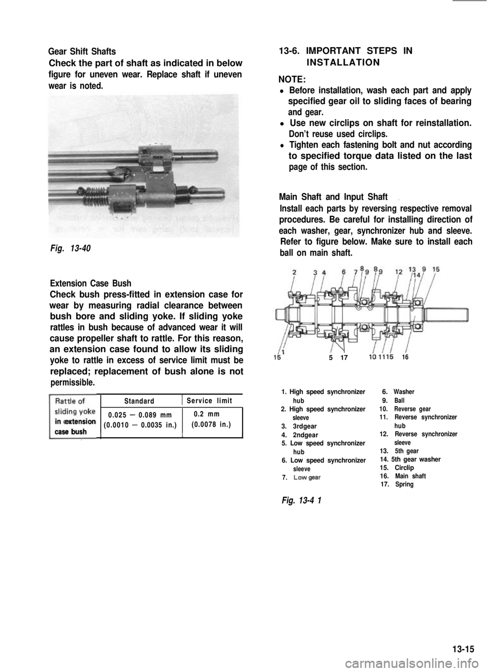
Main Shaft and Input Shaft:,
Install each parts by reversing respective removal
procedures. Be careful for installing direction of
each washer, gear, synchronizer hub and sleeve.
Refer to figure below. Make sure to install each
ball on main shaft.
5 17la 1.11616
1. High speed synchronizer
hub2. High speed synchronizer
sleeve
3.3rdgear
4.2ndgear
5. Low speed synchronizer
hub6. Low speed synchronizer
sleeve
7.Lowgear
6.Washer
9.Ball10.Reverse gear11. Reverse synchronizer
hub
12.Reverse synchronizer
sleeve13.5th gear14. 5th gear washer
15. Circlip
16.
Main shaft17.Spring
Fig. 13-4 1
13-15
Page 284 of 962
4) Uniformly apply sealant (SUZUKI BOND
NO. 1215, 99000-31110) to mating surface
of lower case.
Extension Case
1) Check to ensure that knock pins @ are
fitted.
Fig. 13-77Fig. 13-79
5) Install upper case to lower case by matching
3 shift forks with 3 grooves in synchronizer
sleeve on main shaft respectively.
Fig. 13-78 CiJ Shift forks
2)Apply grease (SUZUKI SUPER GREASE
A 99000-25010) to oil seal lip.
3) Clean surface of extension case to mate
with transmission case and uniformly apply
sealant (SUZUKI BOND No. 1215, 99000-
31110).
Fig. 13-806) Tighten case bolts to specification.
Tightening torque N.mkg-mlb-ftfor transmissioncase bolts18-281.8-2.813.5-20.0
4) Make sure that 3 shift shafts are in neutral
position as shown in Fig. 13-23.
5) Install extension case to transmission case.
6) Tighten case bolts to specification.
Tightening torque N.mkg-mlb-ftfor extension casebolts18-281.8-2.813.5-20.0
13-23