Page 345 of 962
Kingpins and Bearings
Inspect each kingpin closely for dents, signs of
cracking, distortion or any other damage.
Replace the kingpins found in defective condi.
tion.
Check the oil seal for wear or damage. If defec-
tive, replace with new one.
Fig. 17-1-31
Check the kingpin bearings for damage. If
anything is found wrong, replace the bearing
with new one.
Fig. 17-1-32
Steering Knuckle Oil Seal
The oil seal used at the spherical sliding joint
between the knuckle and the inner case accom-
plishes the additional purposes of keeping out
road dust and of acting as the damper for the
steering handwheel.As the wear of this seal
advances, its damping effect decreases and thus
make the front wheel develop a tendency to
“shimmy”not only that road dust begins to
creep into the sliding clearance to promote the
wear of the spherical sliding surfaces.
17-11
Fig. 17-1-33
Page 354 of 962

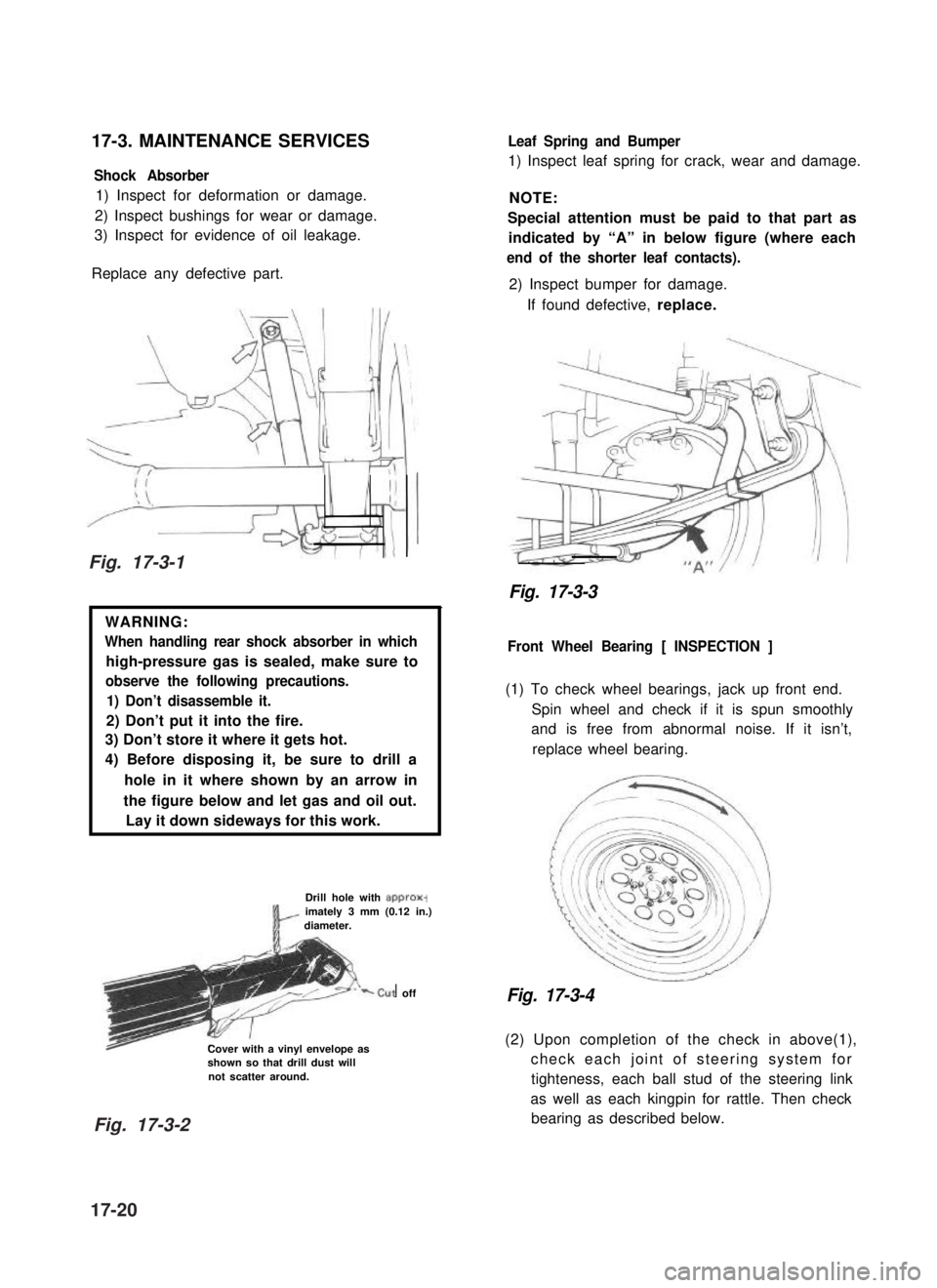
17-3. MAINTENANCE SERVICES
Shock Absorber
1) Inspect for deformation or damage.
2) Inspect bushings for wear or damage.
3) Inspect for evidence of oil leakage.
Replace any defective part.
WARNING:
When handling rear shock absorber in which
high-pressure gas is sealed, make sure to
observe the following precautions.
1) Don’t disassemble it.
2) Don’t put it into the fire.
3) Don’t store it where it gets hot.
4) Before disposing it, be sure to drill a
hole in it where shown by an arrow in
the figure below and let gas and oil out.
Lay it down sideways for this work.
Drill hole with approx-imately 3 mm (0.12 in.)diameter.
‘-cut off
Cover with a vinyl envelope asshown so that drill dust willnot scatter around.
Leaf Spring and Bumper
1) Inspect leaf spring for crack, wear and damage.
NOTE:
Special attention must be paid to that part as
indicated by “A” in below figure (where each
end of the shorter leaf contacts).
2) Inspect bumper for damage.
If found defective, replace.
Fig. 17-3-3
Front Wheel Bearing [ INSPECTION ]
(1) To check wheel bearings, jack up front end.
Spin wheel and check if it is spun smoothly
and is free from abnormal noise. If it isn’t,
replace wheel bearing.
Fig. 17-3-4
(2) Upon completion of the check in above(1),
check each joint of steering system for
tighteness, each ball stud of the steering link
as well as each kingpin for rattle. Then check
bearing as described below.
Fig. 17-3-1
Fig. 17-3-2
17-20
Page 356 of 962

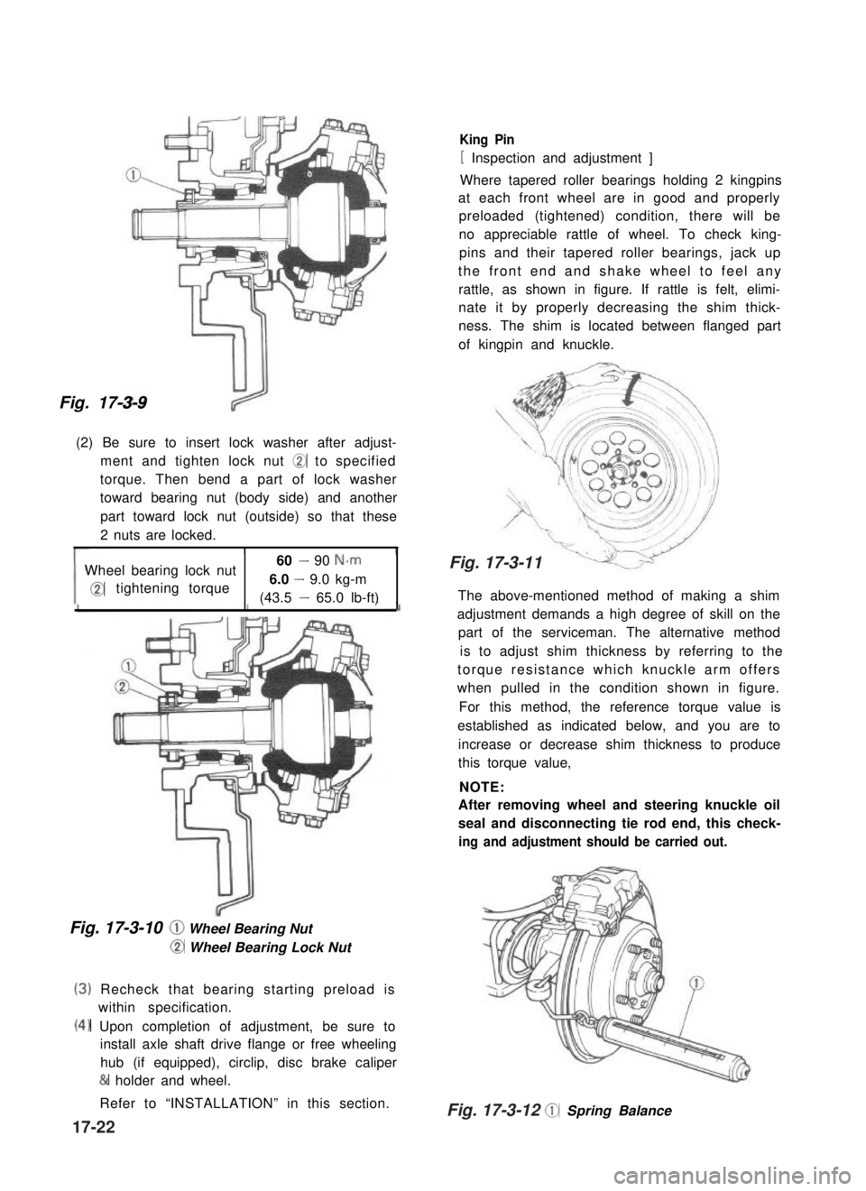
Fig. 17-3-9
(2) Be sure to insert lock washer after adjust-
ment and tighten lock nut @ to specified
torque. Then bend a part of lock washer
toward bearing nut (body side) and another
part toward lock nut (outside) so that these
2 nuts are locked.
Wheel bearing lock nut60 - 90 N-m
@tightening torque6.0 - 9.0 kg-m
(43.5 - 65.0 lb-ft)
Fig. 17-3-10 @ Wheel Bearing Nut
@ Wheel Bearing Lock Nut
(3)
(4)
Recheck that bearing starting preload is
within specification.
Upon completion of adjustment, be sure to
install axle shaft drive flange or free wheeling
hub (if equipped), circlip, disc brake caliper
& holder and wheel.
Refer to “INSTALLATION” in this section.
King Pin
[ Inspection and adjustment ]
Where tapered roller bearings holding 2 kingpins
at each front wheel are in good and properly
preloaded (tightened) condition, there will be
no appreciable rattle of wheel. To check king-
pins and their tapered roller bearings, jack up
the front end and shake wheel to feel any
rattle, as shown in figure. If rattle is felt, elimi-
nate it by properly decreasing the shim thick-
ness. The shim is located between flanged part
of kingpin and knuckle.
The above-mentioned method of making a shim
adjustment demands a high degree of skill on the
part of the serviceman. The alternative method
is to adjust shim thickness by referring to the
torque resistance which knuckle arm offers
when pulled in the condition shown in figure.
For this method, the reference torque value is
established as indicated below, and you are to
increase or decrease shim thickness to produce
this torque value,
NOTE:
After removing wheel and steering knuckle oil
seal and disconnecting tie rod end, this check-
ing and adjustment shouId be carried out.
@ Spring Balance
17-22
Fig. 17-3-12
Fig. 17-3-11
Page 357 of 962

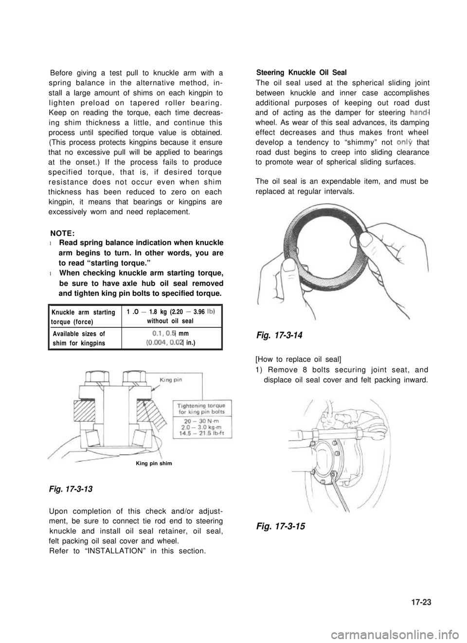
Before giving a test pull to knuckle arm with a
spring balance in the alternative method, in-
stall a large amount of shims on each kingpin to
lighten preload on tapered roller bearing.
Keep on reading the torque, each time decreas-
ing shim thickness a little, and continue this
process until specified torque value is obtained.
(This process protects kingpins because it ensure
that no excessive pull will be applied to bearings
at the onset.) If the process fails to produce
specified torque, that is, if desired torque
resistance does not occur even when shim
thickness has been reduced to zero on each
kingpin, it means that bearings or kingpins are
excessively worn and need replacement.
NOTE:
l Read spring balance indication when knuckle
arm begins to turn. In other words, you are
to read “starting torque.”
l When checking knuckle arm starting torque,
be sure to have axle hub oil seal removed
and tighten king pin bolts to specified torque.
Knuckle arm starting1 .O - 1.8 kg (2.20 - 3.96 lb)
torque (force)without oil seal
Available sizes of0.1,0.5 mm
shim for kingpins(0.004,0.02 in.)
/r--QzL- -\King pin shim
Fig. 17-3-13
Upon completion of this check and/or adjust-
ment, be sure to connect tie rod end to steering
knuckle and install oil seal retainer, oil seal,
felt packing oil seal cover and wheel.
Refer to “INSTALLATION” in this section.
Steering Knuckle Oil Seal
The oil seal used at the spherical sliding joint
between knuckle and inner case accomplishes
additional purposes of keeping out road dust
and of acting as the damper for steering hand-
wheel. As wear of this seal advances, its damping
effect decreases and thus makes front wheel
develop a tendency to “shimmy” not onI9 that
road dust begins to creep into sliding clearance
to promote wear of spherical sliding surfaces.
The oil seal is an expendable item, and must be
replaced at regular intervals.
Fig. 17-3-14
[How to replace oil seal]
1) Remove 8 bolts securing joint seat, and
displace oil seal cover and felt packing inward.
Fig. 17-3-15
17-23
Page 405 of 962

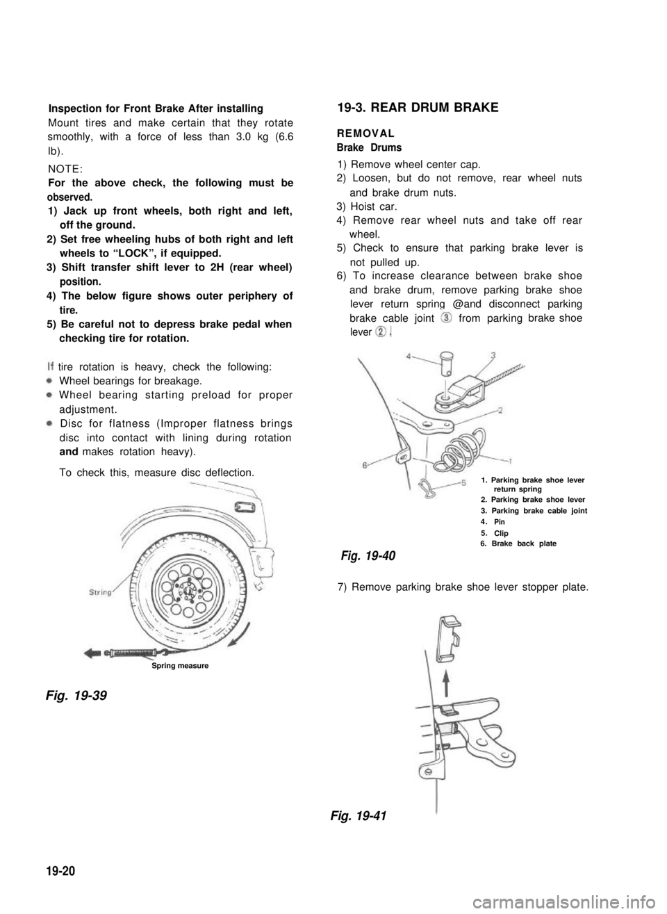
Inspection for Front Brake After installing
Mount tires and make certain that they rotate
smoothly, with a force of less than 3.0 kg (6.6
lb).
NOTE:
For the above check, the following must be
observed.
1) Jack up front wheels, both right and left,
off the ground.
2) Set free wheeling hubs of both right and left
wheels to “LOCK”, if equipped.
3) Shift transfer shift lever to 2H (rear wheel)
position.
4) The below figure shows outer periphery of
tire.
5) Be careful not to depress brake pedal when
checking tire for rotation.
tire rotation is heavy, check the following:
Wheel bearings for breakage.
Wheel bearing starting preload for proper
adjustment.
Disc for flatness (Improper flatness brings
disc into contact with lining during rotation
and makes rotation heavy).
To check this, measure disc deflection.
Spring measure
19-3. REAR DRUM BRAKE
REMOVAL
Brake Drums
1) Remove wheel center cap.
2) Loosen, but do not remove, rear wheel nuts
and brake drum nuts.
3) Hoist car.
4) Remove rear wheel nuts and take off rear
wheel.
5) Check to ensure that parking brake lever is
not pulled up.
6) To increase clearance between brake shoe
and brake drum, remove parking brake shoe
lever return spring @and disconnect parking
brake cable joint 0 from parking
lever 0.
brake shoe
1. Parking brake shoe leverreturn spring2. Parking brake shoe lever
3. Parking brake cable joint
4.Pin
5.Clip6. Brake back plate
Fig.19-40
7) Remove parking brake shoe lever stopper plate.
Fig. 19-39
Fig. 19-41
19-20