Page 454 of 962
21-3. TURN SIGNAL LIGHT AND HAZARD WARNING LIGHT
CIRCUIT DESCRIPTION
1 Right turn signal
2.. Left turn signal
3. Battery4. Main switch
5. Fuse
6. Turn signal and hazard warning switch
7. Turn signal and hazard warning relay
Fig. 21-9
8.Green/Yellow
9.White/Yellow
10.Yellow11.Yellow/Blue
12.Green
13. Black/Blue
14. Green/Red
15.Meter pilot light(Right)
16.Meter pilot light(Left)
17.White/Green
When hazard warning switch is “OFF”, Yellow lead @ is connected to Yellow/Blue lead 0.
When the hazard warning switch is “ON”,White/Green lead @I is connected to Yellow/Blue lead @I, and
Green lead (12)to both Green/Yellow lead @ and Green/Red lead @.
When Turn-signal switch is “ON” for right turn, Green lead @ is connected to Green/Yellow lead @.
When Turn-signal switch is “ON” for left turn, Green lead @ is connected to Green/Red lead @.
21-7
Page 455 of 962

INSPECTION
1) Trouble diagnosis
Symptom
1. Lights will not come on in either left or
right group of light.
2. Hazard light comes on but turn signal
lights will not.
3. No light comes on; or lights light up but
do not flicker.
4. Turn signal lights are satisfactory, but
hazard light will not come on.
5. Flickering freueqncy is erratic, or lights
remain lit.
6. Turning on hazard warning switch lights up
only one group of lights.
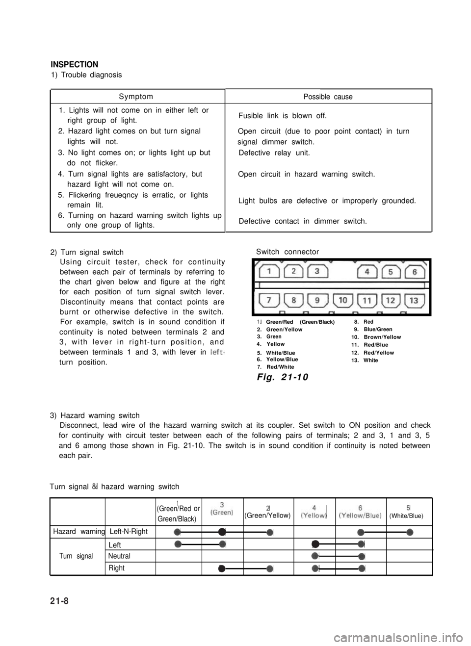
2) Turn signal switch
Using circuit tester, check for continuity
between each pair of terminals by referring to
the chart given below and figure at the right
for each position of turn signal switch lever.
Discontinuity means that contact points are
burnt or otherwise defective in the switch.
For example, switch is in sound condition if
continuity is noted between terminals 2 and
3, with lever in right-turn position, and
between terminals 1 and 3, with lever in left-
turn position.
Possible cause
Fusible link is blown off.
Open circuit (due to poor point contact) in turn
signal dimmer switch.
Defective relay unit.
Open circuit in hazard warning switch.
Light bulbs are defective or improperly grounded.
Defective contact in dimmer switch.
Switch connector
I”””yrm-
1.Green/Red (Green/Black)8.Red
2.Green/Yellow9.Blue/Green3.Green10.Brown/Yellow4.Yellow11.Red/Blue
5.White/Blue12.Red/Yellow6.Yellow/Blue13.White7.Red/White
Fig. 21-10
3) Hazard warning switch
Disconnect, lead wire of the hazard warning switch at its coupler. Set switch to ON position and check
for continuity with circuit tester between each of the following pairs of terminals; 2 and 3, 1 and 3, 5
and 6 among those shown in Fig. 21-10. The switch is in sound condition if continuity is noted between
each pair.
Turn signal & hazard warning switch
1(Green/Redor
Green/Black)
(Grien)2(Green/Yellow) (Yeiow)5(YelloiIBlue) (White/Blue)
Hazard warning Left-N-Right0a-000
Left00l0
Turn signalNeutral*0
Rightla*0
21-8
Page 462 of 962

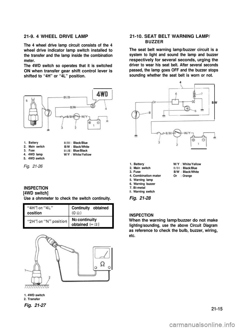
21-9. 4 WHEEL DRIVE LAMP21-10. SEAT BELT WARNING LAMP/
BUZZERThe 4 wheel drive lamp circuit consists of the 4
wheel drive indicator lamp switch installed to
the transfer and the lamp inside the combination
meter.
The 4WD switch so operates that it is switched
ON when transfer gear shift control lever is
shifted to “4H” or “4L” position.
The seat belt warning lamp/buzzer circuit is a
system to light and sound the lamp and buzzer
respectively for several seconds, urging the
driver to wear his seat belt. After several seconds
passed, the lamp goes OFF and the buzzer stops
sounding whether the seat belt is worn or not.
1.BatteryB/B1:Black/Blue2.Main switchB/W:Black/White3.FuseBI/B:Blue/Black4.4WD lampW/Y:White/Yellow5.4WD switch
Fig. 21-26
INSPECTION
[4WD switch]
Use a ohmmeter to check the switch continuity.
I
“4H” or “4L”Continuity obtained
oosition(052)I
I
#,2HM or ##N## positionNO continuity
obtained (- 52 1I
CL-
01
8
4\II
B/W
1. Battery
2. Main switch3. Fuse
4. Combination mater
5. Warning lamp
6. Warning buzzer7. Bi-metal8. Warning switch
W/Y:White/Yellow
BIBI:Black/BlueB/W:Black/White
Or:Orange
Fig. 21-28
INSPECTION
When the warning lamp/buzzer do not make
lighting/sounding, use the above Circuit Diagram
as reference to check the bulb, buzzer, wiring,
etc.
1. 4WD switch
2. Transfer
Fig. 21-2721-15
Page 465 of 962
21-14. FUSE BOX
The fuses in the fuse box is wired as follows.
Head light (R)
Fuse box
Head light (L)Battery7
Horn, Interior light, Door warning
buzzer, ctock (optional)
Stop light
Hazard warning light-W/GI10AW,YI
Cigarette lighter (optional),
Radio (optional)
-w’B++-B7Ignition coil, Fuel cut solenoid,
TWSV, MCSV, vent solenoid,-B/W15A
3
BIBI-
ECM
Heater blower motor-L9
Rear defogger (optional)-Y/G15A
Wiper motor, washer motor-Y/El15A:: BIBI-
Turn signal light, Back-up light-Y10A
Illumination light, License light,
Meter illumination light
-R’y++lFront position and tail light (RI,
Side marker light (RI--RIG5A:: RIB
Lighting switch
Front position and tail light (L), --R,a,
Side marker light (L)
-t
-c
Mainswitch
Tostarter
B/R--,
-
21-18
Page 468 of 962
Fig. 21-39
Instrument Panel Wiring
1.Wire harness No.2
2. Side marker light3.Head light
4.Earth
5.Washer motor
6. To oil pressure gauge
7. To combination light
16
1.Wire harness No. 1
2.To wire~harness No.2
3.To wire harness No.2
4. To fuse box5.Horn relay
6. To combination switch7.To clutch switch
8.Tostop lampswitch15.Doorwarning buzzer
9. To heater blower motor16. Check relay
10.Toradio17.To wipermotor
Il. To heater fan switch18.To illumination lamp
12. To cigar light19. To optional meter
13.Toradio20.Toclock
14.ToECM21.Tometer
Fig. 21-40
21-21