1987 SUZUKI GRAND VITARA coolant
[x] Cancel search: coolantPage 198 of 962
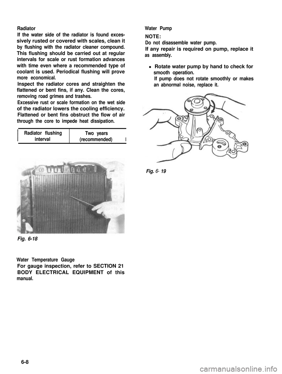
Radiator
If the water side of the radiator is found exces-
sively rusted or covered with scales, clean it
by flushing with the radiator cleaner compound.
This flushing should be carried out at regular
intervals for scale or rust formation advances
with time even where a recommended type of
coolant is used. Periodical flushing will prove
more economical.
Inspect the radiator cores and straighten the
flattened or bent fins, if any. Clean the cores,
removing road grimes and trashes.
Excessive rust or scale formation on the wet side
of the radiator lowers the cooling efficiency.
Flattened or bent fins obstruct the flow of air
through the core to impede heat dissipation.
I
Radiator flushingTwo years
interval(recommended)I
Water Pump
NOTE:
Do not disassemble water pump.
If any repair is required on pump, replace it
as assembly.
l Rotate water pump by hand to check for
smooth operation.
If pump does not rotate smoothly or makes
an abnormal noise, replace it.
Fig. 6- 19
Fig. 6-18
Water Temperature Gauge
For gauge inspection, refer to SECTION 21
BODY ELECTRICAL EQUIPMENT of this
manual.
6-8
Page 200 of 962
Radiator6-5. MAINTENANCE SERVICE
1) Tighten bolts securely for proper installa-
tion. Also, fix joints of 2 hoses with clamps.
Fig. 6-22
2) Install radiator shroud and cooling fan &
clutch at the same time.
3) Tighten shroud bolts and fan clutch nuts.
4) Adjust water pump belt tension.
5) Fill specified amount of coolant.
Water Pump Belt
1) Inspect belt for cracks, cuts, deformation,
wear and cleanliness. If it is necessary to
replace belt, refer to ~6-5 for procedure.
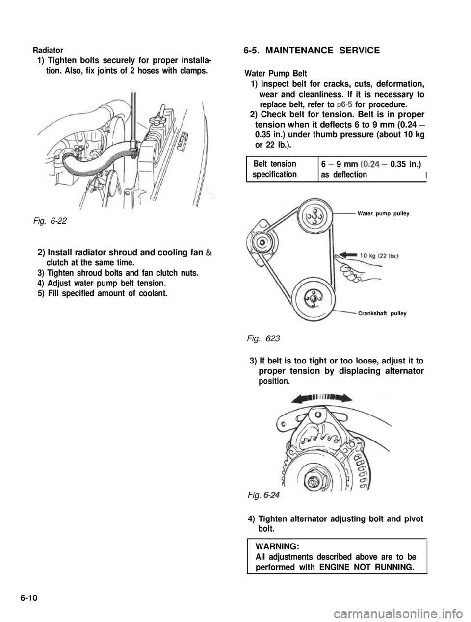
2) Check belt for tension. Belt is in proper
tension when it deflects 6 to 9 mm (0.24 -
0.35 in.) under thumb pressure (about 10 kg
or 22 lb.).
Belt tension
specification
6 - 9 mm (0:24 - 0.35 in.)
as deflectionI
Water pump pulley
Crankshaft pulley
Fig. 623
3) If belt is too tight or too loose, adjust it to
proper tension by displacing alternator
position.
Fig. 6-
4) Tighten alternator adjusting bolt and pivot
bolt.
WARNING:
All adjustments described above are to be
performed with ENGINE NOT RUNNING.
6-10
Page 201 of 962
Coolant
The coolant recovery system is standard. The
coolant in the radiator expands with heat, and
the overflow is collected in the reservoir tank.
When the system cools down, the coolant is
drawn back into the radiator.
The cooling system has been filled at the factory
with a quality coolant that is either 50/50
mixture of water and GOLDEN CRUISER
1200 or 30/70 mixture of water and GOLDEN
CRUISER 1200.
The 50/50 mixture coolant solution provides
freezing protection to -36°C (-33”F), the
30/70 mixture coolant solution provides freezing.
protection to -16°C (3” F).
GOLDEN CRUISER 1200 - “Anti-freeze and
Summer Coolant” - its effects
1) Its freezing temperature is much lower and
depends on the concentration of GOLDEN
CRUISER 1200. It is an anti-freeze coolant.
2) It does not corrode the metal surfaces of the
cooling circuit.It is an anti-corrosion
coolant.
3) It does not develop foam or bubbles. It is a
foam-inhibited coolant.
When changing the engine coolant, use mixture
of 50% water and 50% GOLDEN CRUISER
1200 for the market where ambient tempera-
ture falls lower than -16°C (3°F) in winter and
mixture of 70% water and 30% GOLDEN
CRUISER 1200 for the market where am-
bient temperature doesn’t fall lower than -16°C
(3” F).
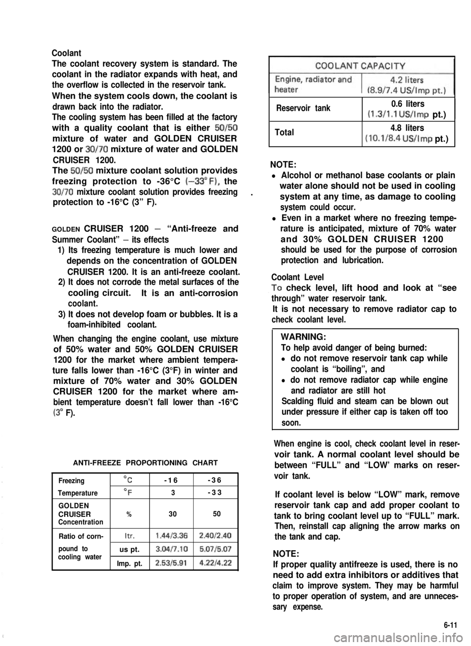
ANTI-FREEZE PROPORTIONING CHART
Freezing
Temperature
GOLDEN
CRUISERConcentration
OC-16-36
OF3-33
%3050
Ratio of corn-Itr.1.4413.362.4012.40
pound tous pt.3.04l7.10 5.0715.07cooling waterImp. pt.2.5315.914.221422
Reservoir tank0.6 liters
(1.3/1.1 US/Imp pt.)I
Total4.8 liters
(10.1/8.4 US/Imp pt.)
NOTE:
l Alcohol or methanol base coolants or plain
water alone should not be used in cooling
system at any time, as damage to cooling
system could occur.
l Even in a market where no freezing tempe-
rature is anticipated, mixture of 70% water
and 30% GOLDEN CRUISER 1200
should be used for the purpose of corrosion
protection and lubrication.
Coolant Level
,To check level, lift hood and look at “see
through” water reservoir tank.
It is not necessary to remove radiator cap to
check coolant level.
WARNING:
To help avoid danger of being burned:
l do not remove reservoir tank cap while
coolant is “boiling”, and
l do not remove radiator cap while engine
and radiator are still hot
Scalding fluid and steam can be blown out
under pressure if either cap is taken off too
soon.
When engine is cool, check coolant level in reser-
voir tank. A normal coolant level should be
between “FULL” and “LOW’ marks on reser-
voir tank.
If coolant level is below “LOW” mark, remove
reservoir tank cap and add proper coolant to
tank to bring coolant level up to “FULL” mark.
Then, reinstall cap aligning the arrow marks on
the tank and cap.
NOTE:
If proper quality antifreeze is used, there is no
need to add extra inhibitors or additives that
claim to improve system. They may be harmful
to proper operation of system, and are unneces-
sary expense.
6-11
Page 202 of 962
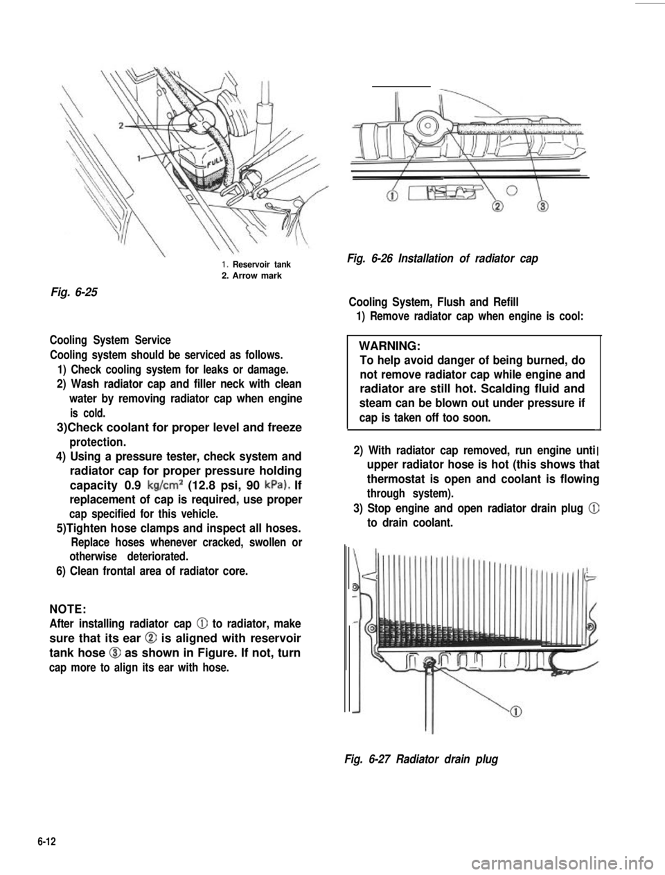
Fig. 6-25
1. Reservoir tank
2. Arrow mark
Cooling System Service
Cooling system should be serviced as follows.
1) Check cooling system for leaks or damage.
2) Wash radiator cap and filler neck with clean
water by removing radiator cap when engine
is cold.
3)Check coolant for proper level and freeze
protection.
4) Using a pressure tester, check system and
radiator cap for proper pressure holding
capacity 0.9 kg/cm2 (12.8 psi, 90 kPa). If
replacement of cap is required, use proper
cap specified for this vehicle.
5)Tighten hose clamps and inspect all hoses.
Replace hoses whenever cracked, swollen or
otherwise deteriorated.
6) Clean frontal area of radiator core.
NOTE:
After installing radiator cap 0 to radiator, make
sure that its ear @ is aligned with reservoir
tank hose @I as shown in Figure. If not, turn
cap more to align its ear with hose.
Fig. 6-26 Installation of radiator cap
Cooling System, Flush and Refill
1) Remove radiator cap when engine is cool:
WARNING:
To help avoid danger of being burned, do
not remove radiator cap while engine and
radiator are still hot. Scalding fluid and
steam can be blown out under pressure if
cap is taken off too soon.d
I2) With radiator cap removed, run engine unti. .upper radiator hose is hot (this shows that
thermostat is open and coolant is flowing
through system).
3) Stop engine and open radiator drain plug @
to drain coolant.
Fig. 6-27 Radiator drain plug
6-12
Page 203 of 962
4) Close drain plug. Add water until system is
filled and run engine until upper radiator
hose is hot again.
5) Repeat steps 3) and 4) several times until
drained liquid is nearly colorless.
6) Drain system and then close radiator drain
plug tightly.
7) Disconnect hose from water reservoir tank.
Remove tank and pour out any fluid. Scrub
and clean inside of tank with soap and water.
Flush it well with clean water and drain.
Reinstall tank and hose.
8)Add proper mixture coolant (refer to page
6-11 of GOLDEN CRUISER 1200 and _,
water to radiator and tank.
Fill radiator to the base of radiator filler
neck and reservoir tank to “FULL” level
mark. Reinstall reservoir tank cap, aligning
the arrow marks on the tank and cap.
9) Run engine, with rediator cap removed, until
radiator upper hose is hot.
10) With engine idling, add coolant to radiator
until level reaches the bottom of filler neck.
Install radiator cap, making sure that the ear
of cap lines up with reservoir tank hose.
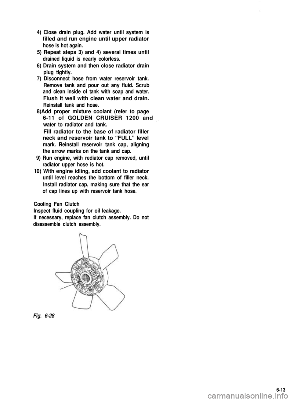
Cooling Fan Clutch
Inspect fluid coupling for oil leakage.
If necessary, replace fan clutch assembly. Do not
disassemble clutch assembly.
Fig. 6-28
6-13
Page 205 of 962
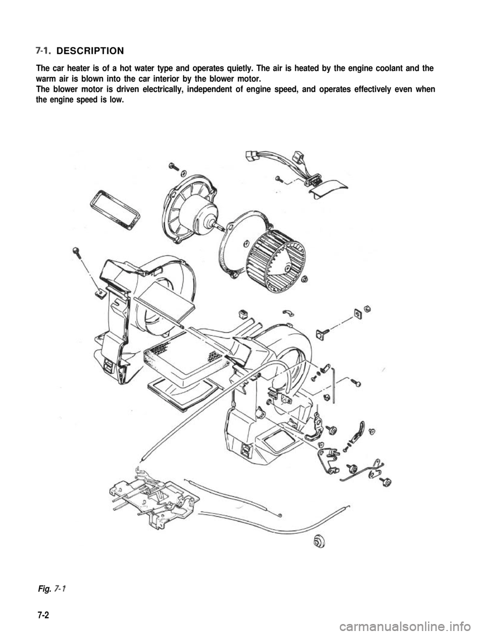
7-l. DESCRIPTION
The car heater is of a hot water type and operates quietly. The air is heated by the engine coolant and the
warm air is blown into the car interior by the blower motor. The blower motor is driven electrically, independent of engine speed, and operates effectively even when
the engine speed is low.
Fig. 7- 1
7-2
Page 209 of 962
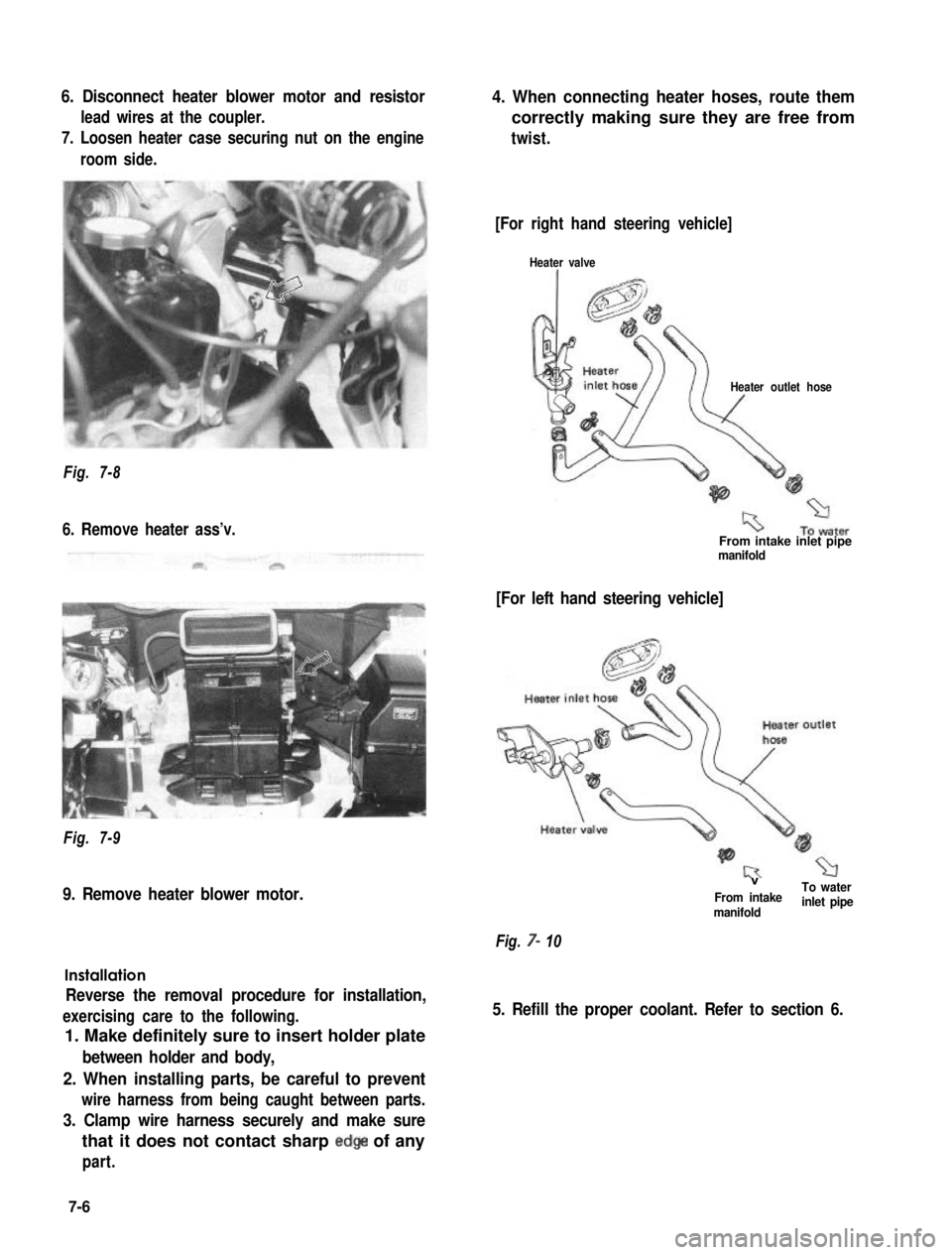
6. Disconnect heater blower motor and resistor
lead wires at the coupler.
7. Loosen heater case securing nut on the engine
room side.
4. When connecting heater hoses, route them
correctly making sure they are free from
twist.
Fig. 7-8
6. Remove heater ass’v.
Fig. 7-9
9. Remove heater blower motor.
Installation
Reverse the removal procedure for installation,
exercising care to the following.
1. Make definitely sure to insert holder plate
between holder and body,
2. When installing parts, be careful to prevent
wire harness from being caught between parts.
3. Clamp wire harness securely and make sure
that it does not contact sharp edge of any
part.
[For right hand steering vehicle]
Heater valve
Heater outlet hose
From intake inlet pipemanifold
[For left hand steering vehicle]
VTo waterFrom intakemanifoldinlet pipe
Fig. 7- 10
5. Refill the proper coolant. Refer to section 6.
7-6
Page 458 of 962
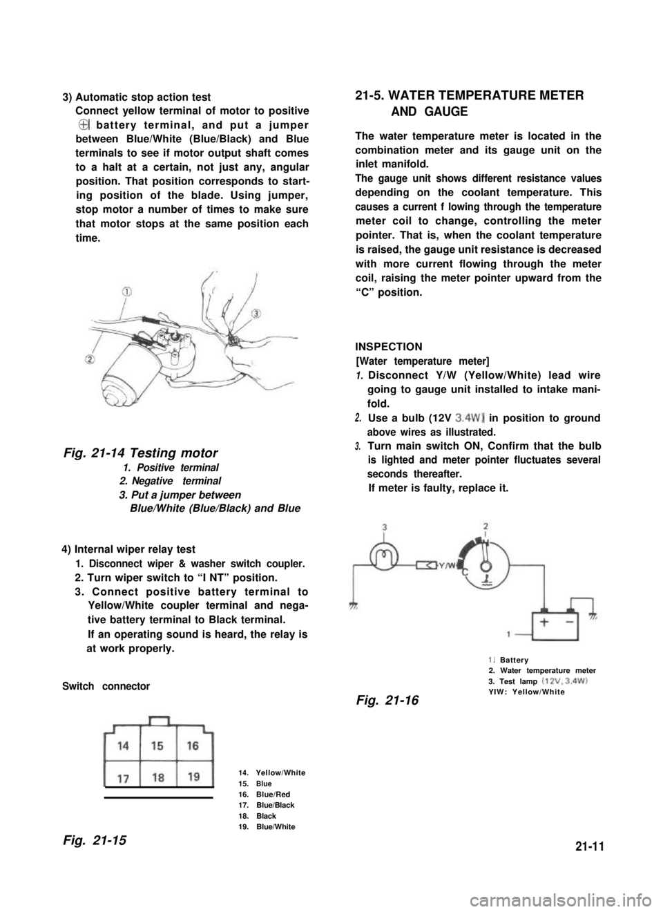
3) Automatic stop action test
Connect yellow terminal of motor to positive
@ battery terminal, and put a jumper
between Blue/White (Blue/Black) and Blue
terminals to see if motor output shaft comes
to a halt at a certain, not just any, angular
position. That position corresponds to start-
ing position of the blade. Using jumper,
stop motor a number of times to make sure
that motor stops at the same position each
time.
Fig. 21-14 Testing motor
1. Positive terminal
2. Negative terminal
3. Put a jumper between
Blue/White (Blue/Black) and Blue
4) Internal wiper relay test
1. Disconnect wiper & washer switch coupler.
2. Turn wiper switch to “I NT” position.
3. Connect positive battery terminal to
Yellow/White coupler terminal and nega-
tive battery terminal to Black terminal.
If an operating sound is heard, the relay is
at work properly.
Switch connector
14.Yellow/White
15.Blue16.Blue/Red17.Blue/Black
18.Black19.Blue/White
21-5. WATER TEMPERATURE METER
AND GAUGE
The water temperature meter is located in the
combination meter and its gauge unit on the
inlet manifold.
The gauge unit shows different resistance values
depending on the coolant temperature. This
causes a current f lowing through the temperature
meter coil to change, controlling the meter
pointer. That is, when the coolant temperature
is raised, the gauge unit resistance is decreased
with more current flowing through the meter
coil, raising the meter pointer upward from the
“C” position.
INSPECTION
[Water temperature meter]
1.
2.
3.
Disconnect Y/W (Yellow/White) lead wire
going to gauge unit installed to intake mani-
fold.
Use a bulb (12V 3.4W) in position to ground
above wires as illustrated.
Turn main switch ON, Confirm that the bulb
is lighted and meter pointer fluctuates several
seconds thereafter.
If meter is faulty, replace it.
1. Battery2. Water temperature meter
3. Test lamp (12V. 3.4W)YIW: Yellow/WhiteFig. 21-16
Fig. 21-1521-11