1987 SUZUKI GRAND VITARA coolant
[x] Cancel search: coolantPage 183 of 962
![SUZUKI GRAND VITARA 1987 Service Repair Manual [Checking sensors and their lead wires]
The sensors constituting the feed back system are; wide open micro switch, idle micro switch, thermal
switch, high altitude compensator, thermal engine room swi SUZUKI GRAND VITARA 1987 Service Repair Manual [Checking sensors and their lead wires]
The sensors constituting the feed back system are; wide open micro switch, idle micro switch, thermal
switch, high altitude compensator, thermal engine room swi](/manual-img/20/57437/w960_57437-182.png)
[Checking sensors and their lead wires]
The sensors constituting the feed back system are; wide open micro switch, idle micro switch, thermal
switch, high altitude compensator, thermal engine room switch and fifth switch. If any of the above
sensors malfunctions or if the sensor circuit has some trouble, signals are not sent to the ECM and conse-
quently the feed back system will not function properly.
Therefore, check each sensor and its circuit according to the following procedure.
1) Turn OFF the ignition switch.
2) Disconnect the coupler from the ECM.
3) Connect the ohmmeter between the terminal @ of the disconnected coupler and the terminal @
(ground) as shown in below figure and measure the resistance. And then repeat the same with each of
the terminals 0, @I, @I, @ and @I.
1. Coupler (Viewed from wireharness side)
2. Wide open micro switch3. idle micro switch
4. Thermal switch
5. Thermal engine room switch6. Fifth switch
7. High altitude compensator
8. Gr/R (Gray/Red) lead wire9. Gr/Y (Gray/Yellow) lead wire10. 81 (Blue) lead wire
11. P/B (Pink/Black) lead wire
12. Gr/B (Gray/Black) lead wire
13. Lg/R (Light green/Red) lead wire
14. B/G (Black/Green) lead wire
Fig. 5-3-43 Checking sensors and their circuits
4) If each ohmmeter reading is as given below, the sensor and its circuit are in good condition. But if not,
the sensor itself may be defective or the lead wire disconnected or out of contact. After checking,
connect the coupler to ECM securely.
Idle micro switch
High altitude compensator
Thermal engine room switch
Wide open micro switch
1 Fifth switch
Ohmmeter
Terminal reading (S2)Condition
When coolant temp. is low.
When coolant temp. is above 46.5’C (I 16’F).
0 1
When engine is warm and accelerator pedal is not depressed.
When accelerator pedal is depressed a little.
00
@
When altitude is below 1,220 m (4,000 ft.).
0When altitude is above 1,220 m (4,000 ft.).
0
When temp. in engine room is low.
When temp. in engine room is above 19.5’C (67°F).
0When accelerator pedal is not depressed or depressed only a
0little.
CoWhen accelerator pedal is depressed all the way.
@ Oa
When gear shift lever is shifted to low, second, third, forth or
reverse gear position.
0When gear shift lever is shifted to fifth gear position.
5-32
Page 188 of 962
EXHAUST GAS RECIRCULATION (EGR)
SYSTEM
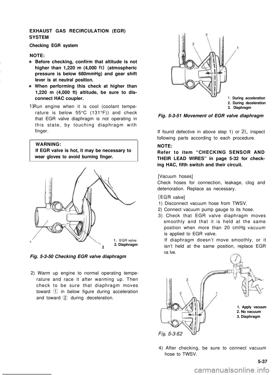
Checking EGR system
NOTE:
1)
Before checking, confirm that altitude is not
higher than 1,220 m (4,000 ft) (atmospheric
pressure is below 680mmHg) and gear shift
lever is at neutral position.
When performing this check at higher than
1,220 m (4,000 ft) altitude, be sure to dis-
connect HAC coupler.
Run engine when it is cool (coolant tempe-
rature is below 55°C (131°F)) and check
that EGR valve diaphragm is not operating in
this state, by touching diaphragm with
finger.
WARNING:
If EGR valve is hot, it may be necessary to
wear gloves to avoid burning finger.
\22. Diaphragm
Fig. 5-3-50 Checking EGR valve diaphragm
2) Warm up engine to normal operating tempe-
rature and race it after warming up. Then
check to be sure that diaphragm moves
toward @ in below figure during acceleration
and toward @ during deceleration.
1. During acceleration
2. During deceleration3. Diaphragm
Fig. 5-3-51 Movement of EGR valve diaphragm
If found defective in above step 1) or 21, inspect
following parts according to each procedure.
NOTE:
Refer to item “CHECKING SENSOR AND
THEIR LEAD WIRES” in page 5-32 for check-
ing HAC, fifth switch and their circuit.
[Vacuum hoses]
Check hoses for connection, leakage, clog and
deterioration. Replace as necessary.
[EGR valve]
1) Disconnect vacuum hose from TWSV.
2) Connect vacuum pump gauge to its hose.
3) Check that EGR valve diaphragm moves
smoothly and that it is held at the same
position when more than 20 cmHg vacuum
is applied to EGR valve.
If diaphragm doesn’t move smoothly, or it
isn’t held at the same position, replace EGR
va Ive.
1. Apply vacuum2. No vacuum
3. Diaphragm
4) After checking, be sure to connect vacuum
hose to TWSV.
5-37
Page 191 of 962
SECTION 6
ENGINE COOLING SYSTEM
CONTENTS
6-l. GENERAL DESCRIPTION .. . . . . . . . . . . . . . . . . . . . ..m..*.........6-2
6-2. REMOVAL...............................................6-5
6.3. INSPECTION OF COMPONENTS..............................6-7
THERMOSTAT...........................................6-7
RADIATOR..............................................6-8
WATER PUMP............................................6-8
6-4.IMPORTANT STEPS FOR REINSTALLATION....................6-9
WATER PUMP..............................................6-9
THERMOSTAT.............................................6-9
COOLING FAN AND WATER PUMP BELT.......................6-9
RADIATOR................................................6-10
6-5. MAINTENANCE SERVICE. . . . . . . . . . . . . . . . . . . . . . . . . . . . . . . . . ...6-10
WATER PUMP BELT.........................................6-10
COOLANT..............................................6-11
COOLANT LEVEL........................................6-11
COOLING SYSTEM SERVICE. . . . . . . . . . . . . . . . . . . . . . . . . . . . . . . .6-12
COOLING SYSTEM, FLUSH AND REFILL . . . . . . . . . . . . . . . . . . . . . . 6-12
6-1
6
Page 192 of 962
6-l. GENERAL DESCRIPTION
The cooling system consists of the radiator cap,
radiator, water reservoir tank, hoses, water
pump, cooling fan & clutch, thermostat. The
radiator is of tube-and-fin type.
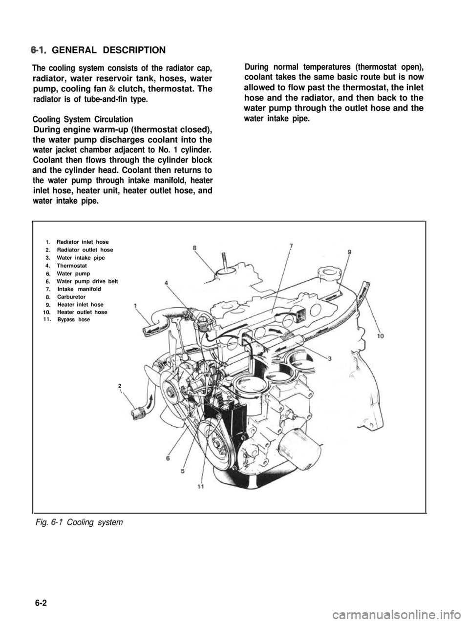
Cooling System Circulation
During engine warm-up (thermostat closed),
the water pump discharges coolant into the
water jacket chamber adjacent to No. 1 cylinder.
Coolant then flows through the cylinder block
and the cylinder head. Coolant then returns to
the water pump through intake manifold, heater
inlet hose, heater unit, heater outlet hose, and
water intake pipe.
During normal temperatures (thermostat open),
coolant takes the same basic route but is now
allowed to flow past the thermostat, the inlet
hose and the radiator, and then back to the
water pump through the outlet hose and the
water intake pipe.
1.Radiator inlet hose
2.Radiator outlet hose
3.Water intake pipe
4.Thermostat
6.Water pump
6.Water pump drive belt
7.Intake manifold
8.Carburetor
9.Heater inlet hose10.Heater outlet hose11.Bypass hose
2\
Fig. 6- 1 Cooling system
6-2
Page 193 of 962
Radiator Cap
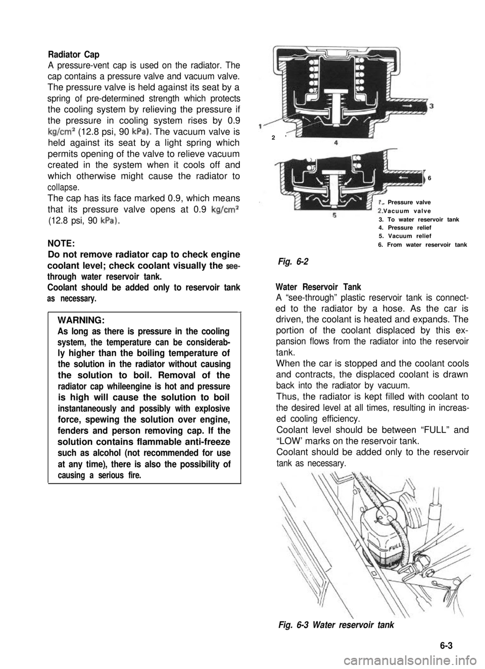
A pressure-vent cap is used on the radiator. The
cap contains a pressure valve and vacuum valve.
The pressure valve is held against its seat by a
spring of pre-determined strength which protects
the cooling system by relieving the pressure if
the pressure in cooling system rises by 0.9
kg/cm2 (12.8 psi, 90 kPa). The vacuum valve is
held against its seat by a light spring which
permits opening of the valve to relieve vacuum
created in the system when it cools off and
which otherwise might cause the radiator to
collapse.
The cap has its face marked 0.9, which means
that its pressure valve opens at 0.9 kg/cm2
(12.8 psi, 90 kPa).
NOTE:
Do not remove radiator cap to check engine
coolant level; check coolant visually the see-
through water reservoir tank.
Coolant should be added only to reservoir tank
as necessary.
4
WARNING:
As long as there is pressure in the cooling
system, the temperature can be considerab-
ly higher than the boiling temperature of
the solution in the radiator without causing
the solution to boil. Removal of the
radiator cap whileengine is hot and pressure
is high will cause the solution to boil
instantaneously and possibly with explosive
force, spewing the solution over engine,
fenders and person removing cap. If the
solution contains flammable anti-freeze
such as alcohol (not recommended for use
at any time), there is also the possibility of
causing a serious fire.
2’
I6
. Pressure valve
Vacuum valve
3. To water reservoir tank4. Pressure relief5. Vacuum relief
6. From water reservoir tank
Fig. 6-2
Water Reservoir Tank
A “see-through” plastic reservoir tank is connect-
ed to the radiator by a hose. As the car is
driven, the coolant is heated and expands. The
portion of the coolant displaced by this ex-
pansion flows from the radiator into the reservoir
tank.
When the car is stopped and the coolant cools
and contracts, the displaced coolant is drawn
back into the radiator by vacuum.
Thus, the radiator is kept filled with coolant to
the desired level at all times, resulting in increas-
ed cooling efficiency.
Coolant level should be between “FULL” and
“LOW’ marks on the reservoir tank.
Coolant should be added only to the reservoir
tank as necessary.
Fig. 6-3 Water reservoir tank
6-3
Page 194 of 962
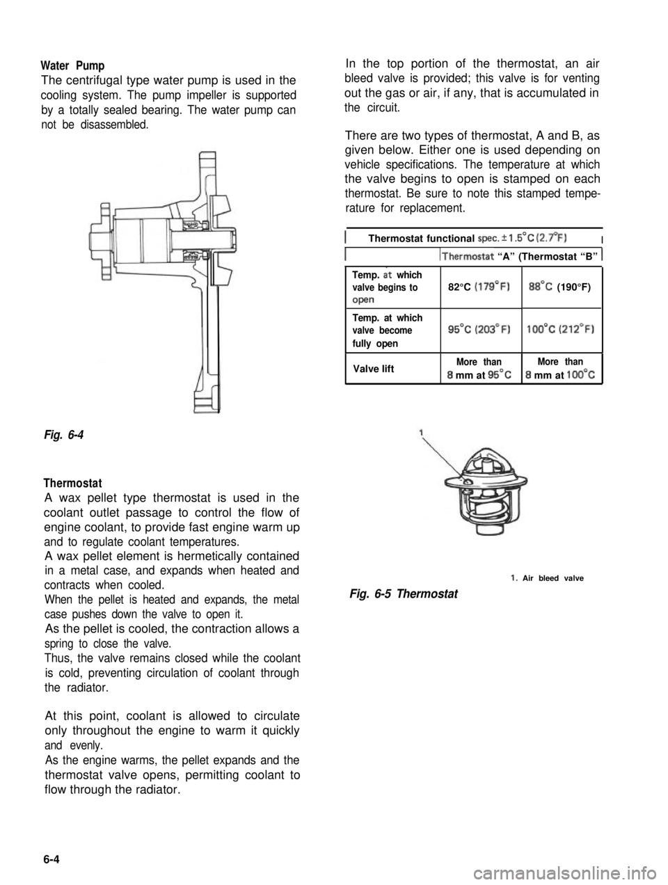
Water Pump
The centrifugal type water pump is used in the
cooling system. The pump impeller is supported
by a totally sealed bearing. The water pump can
not be disassembled.
Fig. 6-4
Thermostat
A wax pellet type thermostat is used in the
coolant outlet passage to control the flow of
engine coolant, to provide fast engine warm up
and to regulate coolant temperatures.
A wax pellet element is hermetically contained
in a metal case, and expands when heated and
contracts when cooled.
When the pellet is heated and expands, the metal
case pushes down the valve to open it.
As the pellet is cooled, the contraction allows a
spring to close the valve.
Thus, the valve remains closed while the coolant
is cold, preventing circulation of coolant through
the radiator.
In the top portion of the thermostat, an air
bleed valve is provided; this valve is for venting
out the gas or air, if any, that is accumulated in
the circuit.
There are two types of thermostat, A and B, as
given below. Either one is used depending on
vehicle specifications. The temperature at which
the valve begins to open is stamped on each
thermostat. Be sure to note this stamped tempe-
rature for replacement.
IThermostat functional spec. f 1.5’C (2.7’F)I
IIThermostat “A” (Thermostat “B” 1
Temp. at which
valve begins to82°C (179’F)
open
BB’C (190°F)
Temp. at which
valve become
fully open
95% (203’F)1OO’C (212’F)
Valve liftMore thanMore than
8 mm at 95’C8 mm at 1OO’C
Fig. 6-5 Thermostat
1. Air bleed valve
At this point, coolant is allowed to circulate
only throughout the engine to warm it quickly
and evenly.
As the engine warms, the pellet expands and the
thermostat valve opens, permitting coolant to
flow through the radiator.
6-4
Page 195 of 962
6-2. .REMOVAL
WARNING:
l Check to make sure that cooling water
temperature is cold before removing any
part of cooling system components.
l Also be sure to disconnect 0 cord from
battery 0 terminal before removing any
part.
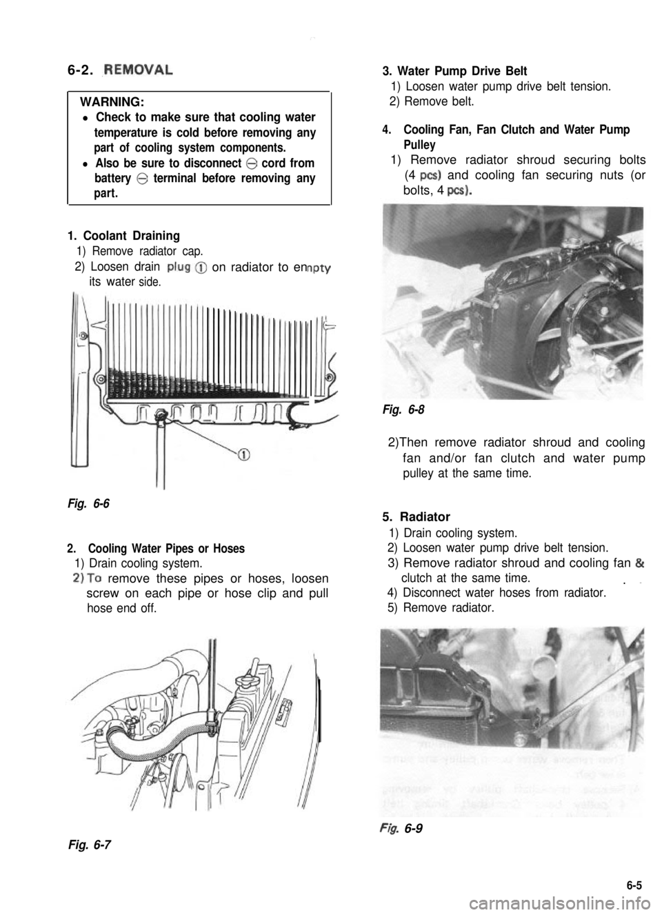
1. Coolant Draining
1) Remove radiator cap.
2) Loosen drain
its waterside.
-on radiator to enPtY
-
Illi
Fig. 6-6
2.Cooling Water Pipes or Hoses
1) Drain cooling system.
2)To remove these pipes or hoses, loosen
screw on each pipe or hose clip and pull
hose end off.
3. Water Pump Drive Belt
1) Loosen water pump drive belt tension.
2) Remove belt.
4.Cooling Fan, Fan Clutch and Water Pump
Pulley
1) Remove radiator shroud securing bolts
(4 PCS) and cooling fan securing nuts (or
bolts, 4 pcs).
Fig. 6-8
2)Then remove radiator shroud and cooling
fan and/or fan clutch and water pump
pulley at the same time.
5. Radiator
1) Drain cooling system.
2) Loosen water pump drive belt tension.
3) Remove radiator shroud and cooling fan &
clutch at the same time.. ”
4) Disconnect water hoses from radiator.
5) Remove radiator.
FI& 6-9
Fig. 6-7
6-5
Page 196 of 962
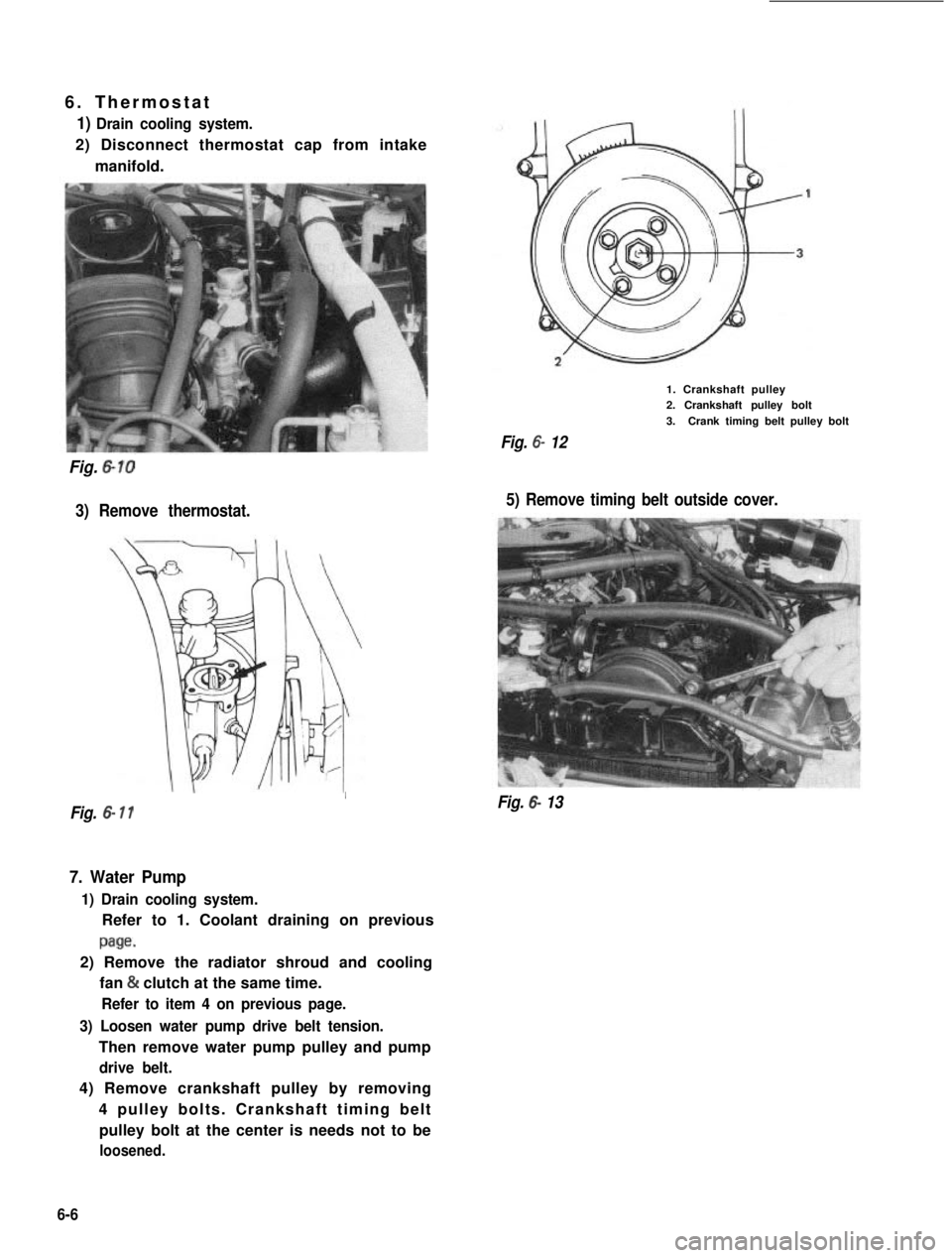
6. Thermostat
1) Drain cooling system.
2) Disconnect thermostat cap from intake
manifold.
Fig. 6-10
3) Remove thermostat.
1. Crankshaft pulley2. Crankshaft pulley bolt
3.Crank timing belt pulley bolt
Fig. 6- 12
5) Remove timing belt outside cover.
I
Fig. 6- 11Fig. 6- 13
7. Water Pump
1) Drain cooling system.
Refer to 1. Coolant draining on previous
page.
2) Remove the radiator shroud and cooling
fan & clutch at the same time.
Refer to item 4 on previous page.
3) Loosen water pump drive belt tension.
Then remove water pump pulley and pump
drive belt.
4) Remove crankshaft pulley by removing
4 pulley bolts. Crankshaft timing belt
pulley bolt at the center is needs not to be
loosened.
6-6