1987 SUZUKI GRAND VITARA coolant
[x] Cancel search: coolantPage 126 of 962
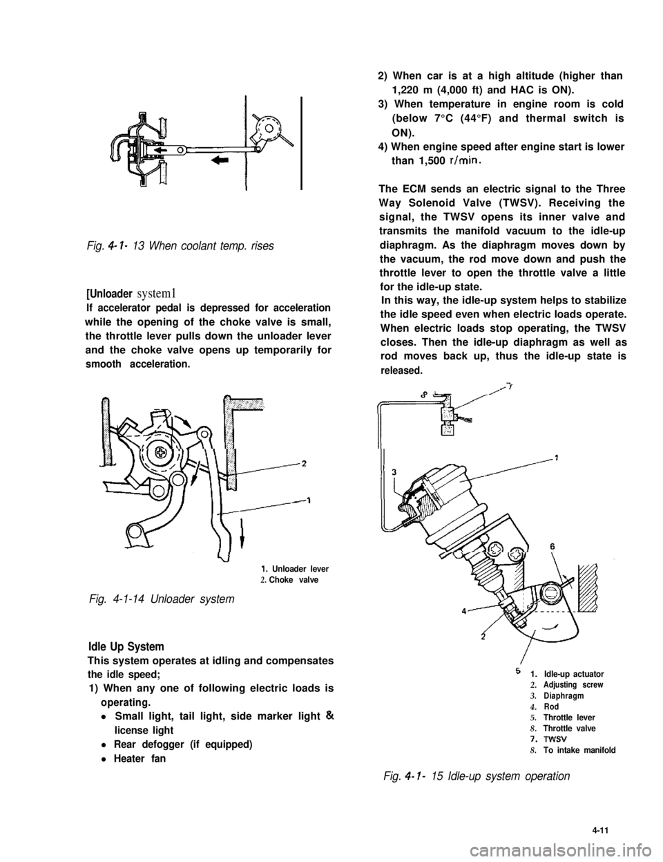
Fig. 4- l- 13 When coolant temp. rises
[Unloader system1
If accelerator pedal is depressed for acceleration
while the opening of the choke valve is small,
the throttle lever pulls down the unloader lever
and the choke valve opens up temporarily for
smooth acceleration.
1. Unloader lever
2. Choke valve
Fig. 4-1-14 Unloader system
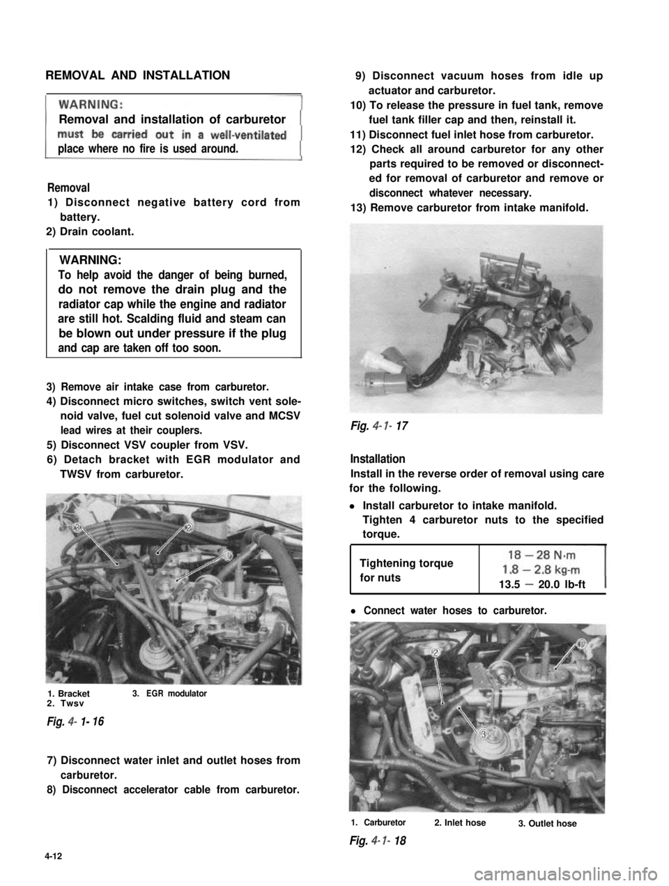
Idle Up System
This system operates at idling and compensates
the idle speed;
1) When any one of following electric loads is
operating.
l Small light, tail light, side marker light &
license light
l Rear defogger (if equipped)
l Heater fan
2) When car is at a high altitude (higher than
1,220 m (4,000 ft) and HAC is ON).
3) When temperature in engine room is cold
(below 7°C (44°F) and thermal switch is
ON).
4) When engine speed after engine start is lower
than 1,500 r/min.
The ECM sends an electric signal to the Three
Way Solenoid Valve (TWSV). Receiving the
signal, the TWSV opens its inner valve and
transmits the manifold vacuum to the idle-up
diaphragm. As the diaphragm moves down by
the vacuum, the rod move down and push the
throttle lever to open the throttle valve a little
for the idle-up state.
In this way, the idle-up system helps to stabilize
the idle speed even when electric loads operate.
When electric loads stop operating, the TWSV
closes. Then the idle-up diaphragm as well as
rod moves back up, thus the idle-up state is
released.
I
5 1.
2.
3.
4.5.
8.
7.
8.
Idle-up actuatorAdjusting screw
Diaphragm
Rod
Throttle lever
Throttle valve
Twsv
To intake manifold
Fig. 4- I- 15 Idle-up system operation
4-11
Page 127 of 962
REMOVAL AND INSTALLATION
Removal and installation of carburetor
place where no fire is used around.
Removal
1) Disconnect negative battery cord from
battery.
2) Drain coolant.
WARNING:
To help avoid the danger of being burned,
do not remove the drain plug and the
radiator cap while the engine and radiator
are still hot. Scalding fluid and steam can
be blown out under pressure if the plug
and cap are taken off too soon.
3) Remove air intake case from carburetor.
4) Disconnect micro switches, switch vent sole-
noid valve, fuel cut solenoid valve and MCSV
lead wires at their couplers.
5) Disconnect VSV coupler from VSV.
6) Detach bracket with EGR modulator and
TWSV from carburetor.
1. Bracket3.EGRmodulator2. Twsv
Fig. 4- 1-16
7) Disconnect water inlet and outlet hoses from
carburetor.
8) Disconnect accelerator cable from carburetor.
9) Disconnect vacuum hoses from idle up
actuator and carburetor.
10) To release the pressure in fuel tank, remove
fuel tank filler cap and then, reinstall it.
11) Disconnect fuel inlet hose from carburetor.
12) Check all around carburetor for any other
parts required to be removed or disconnect-
ed for removal of carburetor and remove or
disconnect whatever necessary.
13) Remove carburetor from intake manifold.
Fig. 4- 7- 17
Installation
Install in the reverse order of removal using care
for the following.
l Install carburetor to intake manifold.
Tighten 4 carburetor nuts to the specified
torque.
Tightening torque
for nuts13.5 - 20.0 lb-ft
l Connect water hoses to carburetor.
1. Carburetor
Fig. 4- I- 18
2. Inlet hose3. Outlet hose
4-12
Page 134 of 962
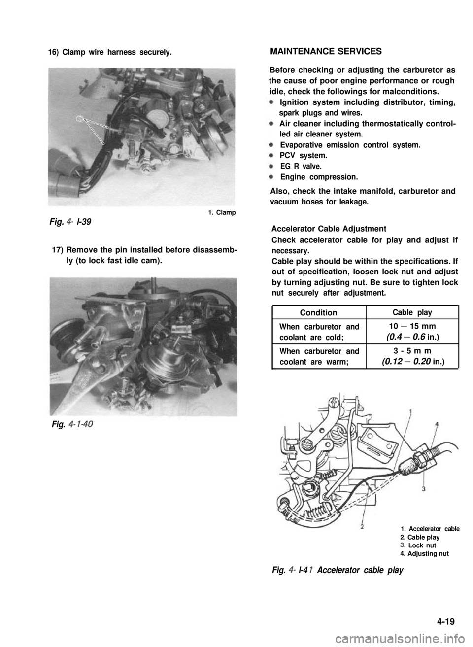
16) Clamp wire harness securely.MAINTENANCE SERVICES
Fig. 4- l-39
1. Clamp
17) Remove the pin installed before disassemb-
ly (to lock fast idle cam).
Fig. 4- l-40
Before checking or adjusting the carburetor as
the cause of poor engine performance or rough
idle, check the followings for malconditions.
Ignition system including distributor, timing,
spark plugs and wires.
Air cleaner including thermostatically control-
led air cleaner system.
Evaporative emission control system.
PCV system.
EG R valve.
Engine compression.
Also, check the intake manifold, carburetor and
vacuum hoses for leakage.
Accelerator Cable Adjustment
Check accelerator cable for play and adjust if
necessary.
Cable play should be within the specifications. If
out of specification, loosen lock nut and adjust
by turning adjusting nut. Be sure to tighten lock
nut securely after adjustment.
Condition
When carburetor and
coolant are cold;
When carburetor and
coolant are warm;
Cable play
10 - 15 mm
(0.4 - 0.6 in.)
3-5mm
(0.12 - 0.20 in.)
1. Accelerator cable
2. Cable play
3. Lock nut
4. Adjusting nut
Fig. 4- l-4 1 Accelerator cable play
4-19
Page 137 of 962
![SUZUKI GRAND VITARA 1987 Service Repair Manual Ambient temperatureClearance
Fig. 4-l-47
Choke Adjustment
Perform following check and adjustments with
air intake case removed when engine is cold.
[Choke valve]
1) Check choke valve for smooth moveme SUZUKI GRAND VITARA 1987 Service Repair Manual Ambient temperatureClearance
Fig. 4-l-47
Choke Adjustment
Perform following check and adjustments with
air intake case removed when engine is cold.
[Choke valve]
1) Check choke valve for smooth moveme](/manual-img/20/57437/w960_57437-136.png)
Ambient temperatureClearance
Fig. 4-l-47
Choke Adjustment
Perform following check and adjustments with
air intake case removed when engine is cold.
[Choke valve]
1) Check choke valve for smooth movement by
pushing it with a finger.
Fig. 4-l-48 Choke valve
2) Make sure that choke valve is closed almost
completely when ambient temperature is
below 25°C (77” F) and engine is cold.
3) Check to ensure that choke valve to carbure-
tor bore clearance is within following specifi-
cations when engine is cool.
I.6 mmC&n*?.:.. \
NOTE:
As ambient temperature or engine coolant
temperature rises high, clearance increases.
1. Choke valve2. Thickness gauge
Fig. 4- 149 Choke valve to carbure tar bore
clearance
4) If clearance is found excessively large or
small in the above check, check strangler
spring, choke piston and each link in choke
system for smooth operation. Lubricate
choke valve shaft and each link with spray
lubricant if necessary.
Fig. 4-l-50
4-22
Page 161 of 962
![SUZUKI GRAND VITARA 1987 Service Repair Manual COMPUTER CONTROLLED EMISSION CONTROL SYSTEM
[Feed back system]
A prime purpose of this system is to maintain a controlled air fuel ratio, allowing the catalyst to reduce
oxides of nitrogen, hydrocarbo SUZUKI GRAND VITARA 1987 Service Repair Manual COMPUTER CONTROLLED EMISSION CONTROL SYSTEM
[Feed back system]
A prime purpose of this system is to maintain a controlled air fuel ratio, allowing the catalyst to reduce
oxides of nitrogen, hydrocarbo](/manual-img/20/57437/w960_57437-160.png)
COMPUTER CONTROLLED EMISSION CONTROL SYSTEM
[Feed back system]
A prime purpose of this system is to maintain a controlled air fuel ratio, allowing the catalyst to reduce
oxides of nitrogen, hydrocarbons, carbon monoxide and to improve fuel economy simultaneously.
The electronic control module (ECM) and the oxygen sensor are provided in this system.
The oxygen sensor mounted on the exhaust manifold monitors the exhaust gas air fuel ratio and signals to
the ECM.
The ECM processes the oxygen sensor signal and controls carburetor air fuel ratio by the operation of the
mixture control solenoid in the carburetor.
Thus the signal of the exhaust gas air fuel ratio sensed by the oxygen sensor is fed back to ECM and the
carburetor air fuel ratio is controlled.
[Electronic control module (ECM)]
The ECM controls the fuel cut system, idle-up system, bowl vent system, EGR system and secondary
throttle valve system, as well as the feed back system. The ECM is located under the glove box of the
instrument main panel. Refer to Fig. 5-l -9.
I1
* Engine coolant
temperature
* Engine speed
-Electronic
controlmodule
I I
* Throttle positiont(Micro Switches)
I I I\-
* Fuel cut solenoid valve
-44
* Engine room
- * Vent solenoid valvetempe.rature
* Idle-up actuator (TWSV)* Electric load
* Secondary throttle valve (VSV) , _ ~
r* Mixture control
solenoid valve
* Barometric
pressure
+ ECM supply
voltage
* Gear position
Fig. 5-l-8Computer con trolled emissioncon trot s ys tern
5- 10
Page 162 of 962
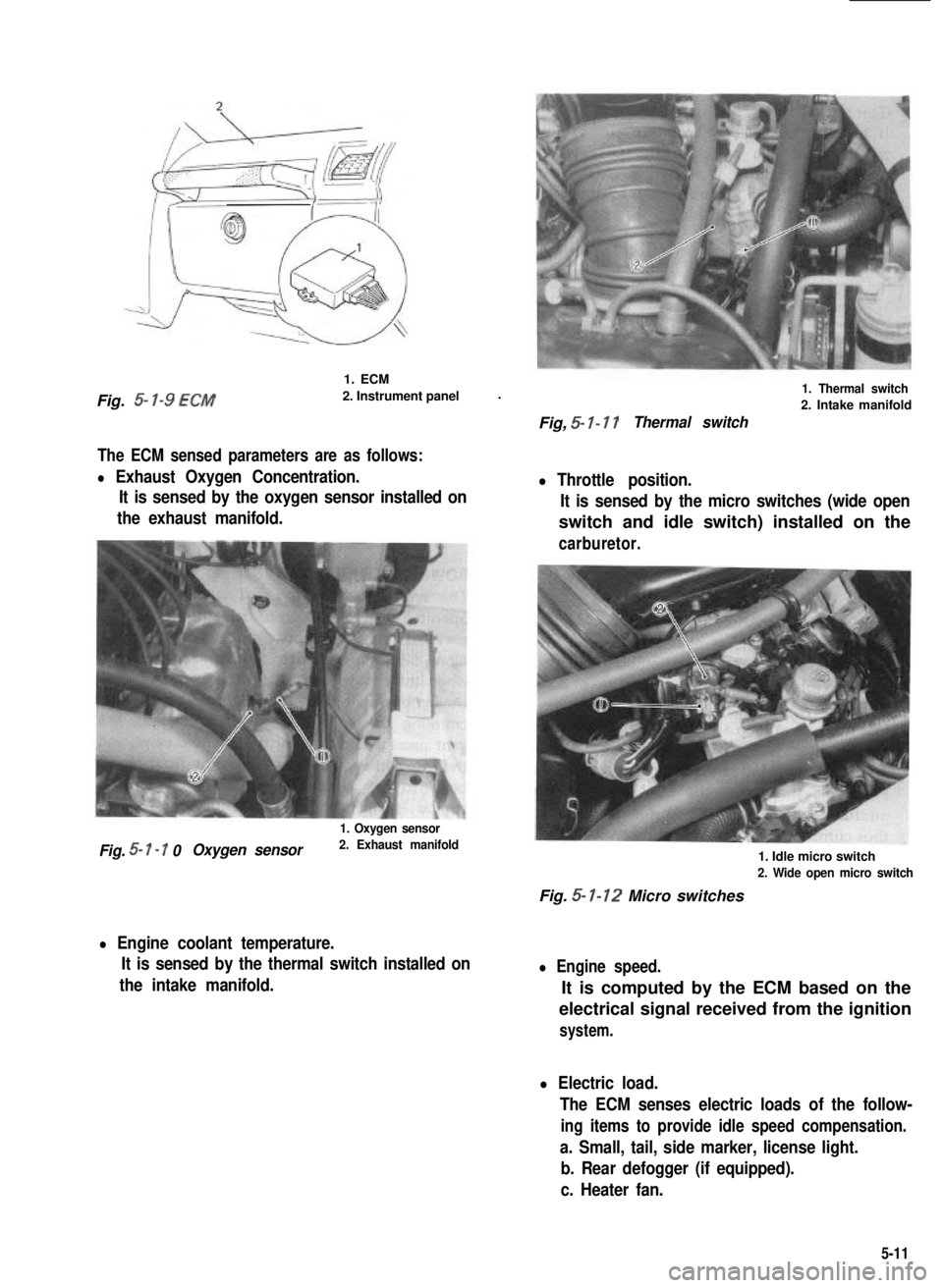
Fig. 5- l-9 ECM
1. ECM
2. Instrument panel.
The ECM sensed parameters are as follows:
l Exhaust Oxygen Concentration.
It is sensed by the oxygen sensor installed on
the exhaust manifold.
1. Oxygen sensor
Fig. 5- I - 7 0Oxygen sensor2. Exhaust manifold
l Engine coolant temperature.
It is sensed by the thermal switch installed on
the intake manifold.
1. Thermal switch
2. Intake manifold
Fig, 5- I- 17Thermal switch
l Throttle position.
It is sensed by the micro switches (wide open
switch and idle switch) installed on the
carburetor.
1. Idle micro switch
2. Wide open micro switch
Fig. 5- 1-12 Micro switches
l Engine speed.
It is computed by the ECM based on the
electrical signal received from the ignition
system.
l Electric load.
The ECM senses electric loads of the follow-
ing items to provide idle speed compensation.
a. Small, tail, side marker, license light.
b. Rear defogger (if equipped).
c. Heater fan.
5-11
Page 164 of 962
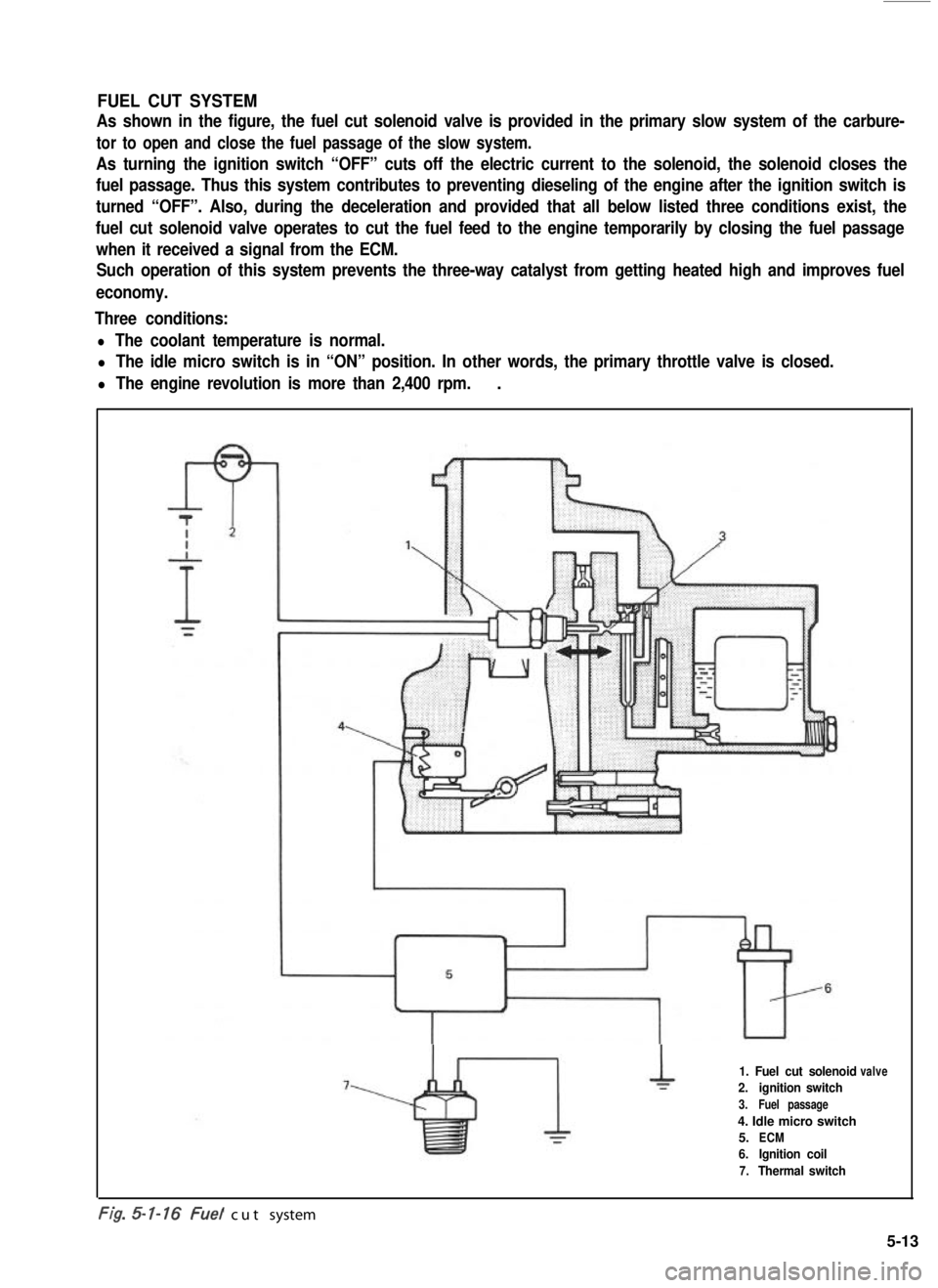
FUEL CUT SYSTEM
As shown in the figure, the fuel cut solenoid valve is provided in the primary slow system of the carbure-
tor to open and close the fuel passage of the slow system.
As turning the ignition switch “OFF” cuts off the electric current to the solenoid, the solenoid closes the
fuel passage. Thus this system contributes to preventing dieseling of the engine after the ignition switch is
turned “OFF”. Also, during the deceleration and provided that all below listed three conditions exist, the
fuel cut solenoid valve operates to cut the fuel feed to the engine temporarily by closing the fuel passage
when it received a signal from the ECM.
Such operation of this system prevents the three-way catalyst from getting heated high and improves fuel
economy.
Three conditions:
l The coolant temperature is normal.
l The idle micro switch is in “ON” position. In other words, the primary throttle valve is closed.
l The engine revolution is more than 2,400 rpm..
1. Fuel cut solenoid
2.ignition switch
3.Fuel passage
4. Idle micro switch
5.ECM
6.Ignition coil
7.Thermal switch
valve
-. .t/g. cut system
5-13
Page 165 of 962
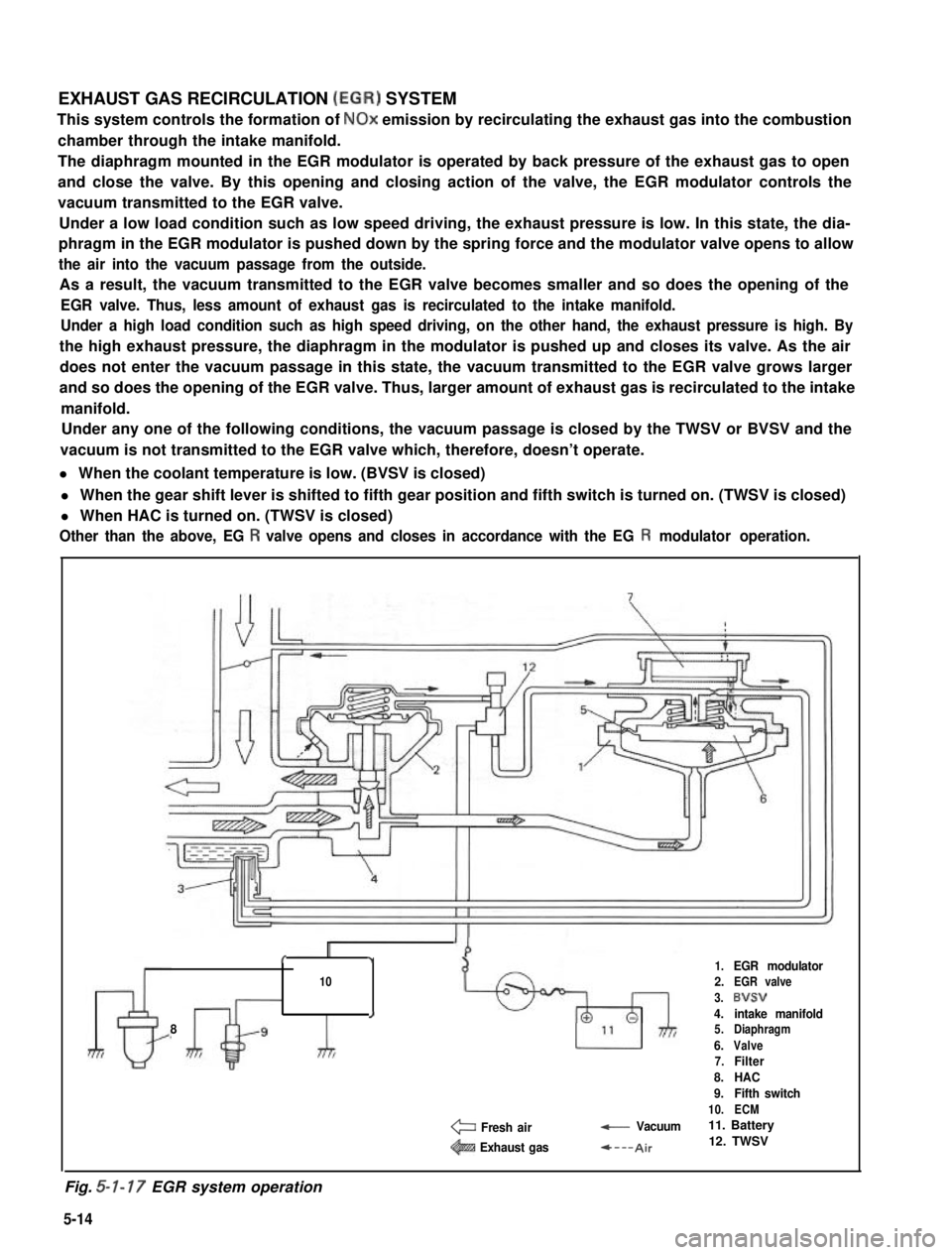
EXHAUST GAS RECIRCULATION (EGR) SYSTEM
This system controls the formation of NOx emission by recirculating the exhaust gas into the combustion
chamber through the intake manifold.
The diaphragm mounted in the EGR modulator is operated by back pressure of the exhaust gas to open
and close the valve. By this opening and closing action of the valve, the EGR modulator controls the
vacuum transmitted to the EGR valve.
Under a low load condition such as low speed driving, the exhaust pressure is low. In this state, the dia-
phragm in the EGR modulator is pushed down by the spring force and the modulator valve opens to allow
the air into the vacuum passage from the outside.
As a result, the vacuum transmitted to the EGR valve becomes smaller and so does the opening of the
EGR valve. Thus, less amount of exhaust gas is recirculated to the intake manifold.
Under a high load condition such as high speed driving, on the other hand, the exhaust pressure is high. By
the high exhaust pressure, the diaphragm in the modulator is pushed up and closes its valve. As the air
does not enter the vacuum passage in this state, the vacuum transmitted to the EGR valve grows larger
and so does the opening of the EGR valve. Thus, larger amount of exhaust gas is recirculated to the intake
manifold.
Under any one of the following conditions, the vacuum passage is closed by the TWSV or BVSV and the
vacuum is not transmitted to the EGR valve which, therefore, doesn’t operate.
l When the coolant temperature is low. (BVSV is closed)
l When the gear shift lever is shifted to fifth gear position and fifth switch is turned on. (TWSV is closed)
l When HAC is turned on. (TWSV is closed)
Other than the above, EG R valve opens and closes in accordance with the EG R modulator operation.
8
c,1.EGR modulator102.EGR valve
3.8VSV
J4.intake manifold5.Diaphragm
6.Valve7.Filter
8.HAC
9.Fifth switch
10.ECM
e Fresh air- Vacuum11. Battery
@!B Exhaust gas*---Air12. TWSV
Fig. 5-l- 17 EGR system operation
5-14