Page 291 of 513
ti
r
f
o
1
b
4
AI
I
W
n
t
i
i
1
i
f
f
7i
ii
y
0
r
1
J
1
t
I
r
I
DATSUN
1200
SERVICE
MANUAL
MODEL
8110
SERIES
N
I
NISSAN
MOTOR
CO
LTD
TOKYO
JAPAN
j
QUICK
REFERENCE
INDEX
GENERAL
INfORMATION
GI
EMISSION
CONTROL
AND
TUNE
UP
ET
ENGINE
MECHANICAL
EM
REAR
AXlE
8
REAR
SUSPENSiON
BRAKE
WHEEL
AND
TIRE
STEERING
ENGINE
CONTROL
fUEL
8
EXHAUST
BODY
BODY
ElECTRICAL
SERVICE
EQUIPMENT
Page 301 of 513

GENERAL
INFORMATION
steering
wheel
should
be
secured
to
maintain
a
straight
ahead
position
TIE
DOWN
The
front
tie
down
hook
is
used
the
both
front
end
of
tension
rod
Do
not
apply
the
hook
at
the
center
of
tension
rod
or
suspension
member
The
rear
tie
down
hook
is
used
the
both
front
shackle
of
rear
spring
APPROXIMATE
REFILL
CAPACITY
Liter
U
S
A
measure
I
Imp
measure
Sedan
Fuel
tank
Coupe
with
heater
Cooling
system
without
heater
40
L
38
L
4
9
L
4
2
L
2
7
L
0
54
L
1
2
L
5
5
L
0
75
L
0
24
L
Oil
pan
Oilf1lter
Transmission
case
Manual
Automatic
Differential
case
Steering
gear
box
RECOMMENDED
GASOLINE
FUEL
Use
a
no
lead
or
low
lead
gasoline
with
a
minimum
octane
rating
of
87
the
average
of
the
Research
and
1O
gal
8Y
gal
10
gal
8
gal
5
v
qt
4
M
qt
4
Y
6
qt
3
Y
qt
2Ji
qt
2
qt
1
pt
I
pt
2
pt
2
pt
5Ji
qt
4
qt
1
pt
1
pt
pt
pi
Motor
Octane
Numbers
in
the
U
S
When
the
figure
is
based
on
the
Research
Octane
Number
use
a
gasoline
with
a
minimum
octane
rating
of
91
RON
in
Canada
RECOMMENDED
LUBRICANTS
GI
5
r
Page 475 of 513

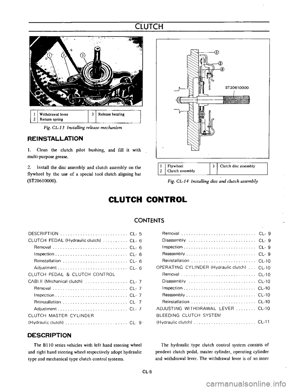
CLUTCH
J
I
I
Withdrawal
lever
2
Return
spring
I
31
Release
bearing
ST20610000
iwn
rm
hj
sf
W
Fig
CL
13
Installing
release
mechanism
REINSTALLATION
L
Clean
the
clutch
pilot
bushing
and
fill
it
with
multi
purpose
grease
2
Install
the
disc
assembly
and
clutch
assembly
on
the
flywheel
by
the
use
of
a
special
tool
clutch
aligning
bar
ST206
I
0000
12
I
Flywheel
Clutch
assembly
131
Clutch
disc
assembly
Fig
CL
14
Installing
disc
and
clutch
assembly
CLUTCH
CONTROL
CONTENTS
DESCRIPTION
CL
5
Removal
CL
9
CLUTCH
PEDAL
Hydraulic
clutch
CL
6
Disassembly
CL
9
Removal
CL
6
Inspection
CL
9
Inspection
CL
6
Reassembly
CL
9
Reinstallation
CL
6
Reinstallation
CL
10
Adjustment
CL
6
OPERATING
CYLINDER
Hydraulic
clutch
CL
10
CLUTCH
PEDAL
CLUTCH
CONTROL
Removal
CL
10
CABLE
Mechanical
clutch
CL
7
Disassembly
CL
10
Removal
CL
7
Inspection
CL
10
Inspection
CL
7
Reassembly
CL
10
Reinstallation
CL
7
Reinstallation
CL
10
Adjustment
CL
7
ADJUSTING
WITHDRAWAL
LEVER
CL
10
CLUTCH
MASTER
CYLINDER
BLEEDING
CLUTCH
SYSTEM
Hydraulic
clutch
CL
9
Hydraulic
clutch
CL
11
DESCRIPTION
The
B
I
IO
series
vehicles
with
left
hand
steering
wheel
and
right
hand
steering
wheel
respectively
adopt
hydraulic
type
and
mechanical
type
clutch
control
systems
The
hydraulic
type
clutch
control
system
consists
of
pendent
clutch
pedal
master
cylinder
operating
cylinder
and
withdrawal
lever
The
withdrawal
lever
is
of
an
inner
CL
5
Page 504 of 513
TRANSMISSION
COLUMN
SHIFT
CONTROL
SYSTEM
Removal
Remove
the
steering
wheel
assembly
Fig
TM
54
Rem01
ing
steering
wheel
2
Remove
the
steering
column
shell
cover
turn
signal
and
lighting
switch
completely
Fig
TM
55
Removing
steering
column
shell
cover
Fig
TM
56
Removing
turn
signal
and
lighting
switch
3
Remove
the
snap
ring
and
control
lever
pivot
pin
and
withdraw
the
hand
lever
A
A
V
l
Y
e
f
I
1
I
V
e
tl
f
r
4
2i
L
1
I
Snap
ring
2
Control
lever
pivot
pin
I
3
I
C
washer
Fig
TM
57
Withdrawing
hand
ever
4
Remove
the
C
washer
TM
17
i
MI
ig
r
M
5J
emOVing
change
lever
J
y
Ji
1
r
oJ