1973 DATSUN B110 steering wheel
[x] Cancel search: steering wheelPage 89 of 513
FRONT
AXLE
FRONT
SUSPENSION
FRONT
AXLE
AND
SUSPENSION
ASSEMBLY
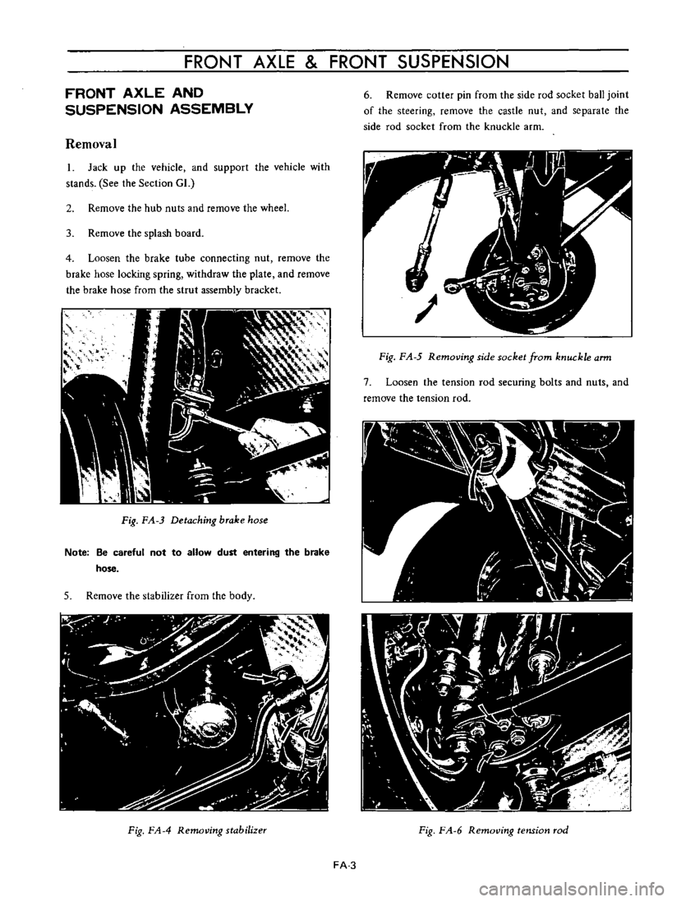
Removal
1
Jack
up
the
vehicle
and
support
the
vehicle
with
stands
See
the
Section
GL
2
Remove
the
hub
nuts
and
remOve
the
wheel
3
Remove
the
splash
board
4
Loosen
the
brake
tube
connecting
nut
remove
the
brake
hose
locking
spring
withdraw
the
plate
and
remOve
the
brake
hose
from
the
strul
assembly
bracket
Fig
FA
3
Detaching
brake
hose
Note
Be
careful
not
to
allow
dust
entering
the
brake
hose
5
Remove
the
stabilizer
from
the
body
Fig
FA
4
Removing
stabilizer
6
Remove
cotter
pin
from
the
side
rod
socket
ball
joint
of
the
steering
remove
the
castle
nut
and
separate
the
side
rod
socket
from
the
knuckle
arm
Fig
F
A
5
Removing
side
socket
from
knuckle
arm
7
Loosen
the
tension
rod
securing
bolts
and
nuts
and
remove
the
tension
rod
Fig
F
A
6
RemotJing
tension
rod
FA
3
Page 107 of 513
FRONT
AXLE
FRONT
SUSPENSION
ADJUSTMENT
CONTENTS
ADJUSTMENT
DATA
ADJUSTMENT
OF
WHEEL
ALIGNMENT
ADJUSTMENT
OF
VEHICLE
LEVEL
FA
21
FA
22
FA
22
1
Carry
out
wheel
alignment
on
a
flat
surface
with
tire
air
pressure
adjusted
to
the
normal
pressure
2
Thoroughly
check
all
component
parts
of
the
steering
and
suspension
systems
and
repair
or
replace
AD
JUSTMENT
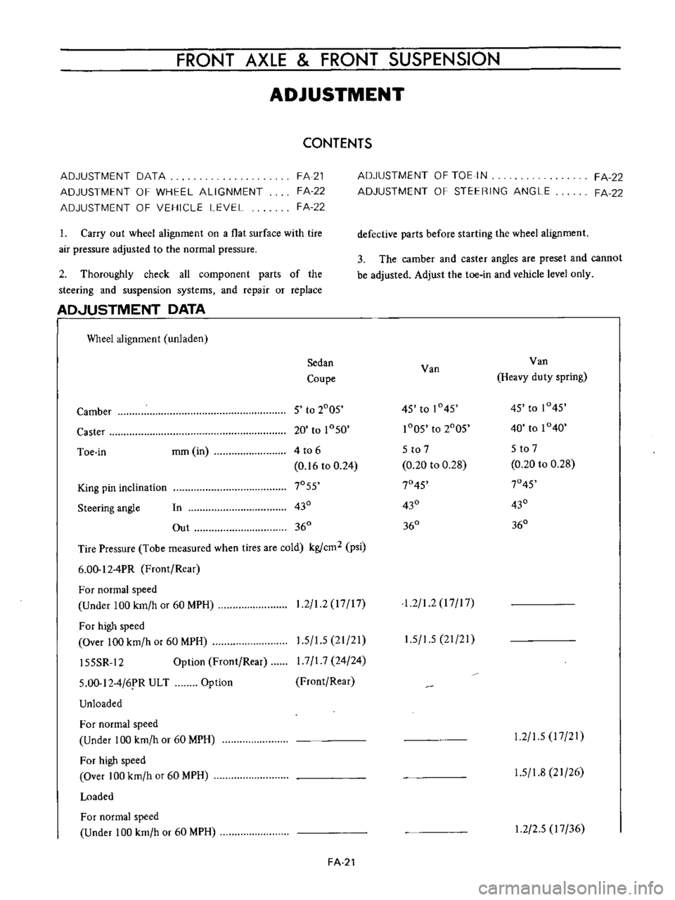
DATA
I
Wheel
alignment
unladen
Sedan
Coupe
Camber
5
to
2005
Caster
20
to
1050
Toe
in
mm
in
4
to
6
0
16
to
0
24
King
pin
inclination
7055
Steering
angle
In
430
Out
360
Tire
Pressure
Tobe
measured
when
tires
are
cold
kgfcm2
psi
6
00
12
4PR
Front
Rear
For
normal
speed
Under
100
km
h
or
60
MPH
For
high
speed
Over
100
km
h
or
60
MPH
15SSR
12
Option
Front
Rear
1
2
1
2
17
17
1
5
1
5
21
21
I
7
I
7
24
24
Front
Rear
5
00
12
4
6
R
ULT
Unloaded
Option
For
normal
speed
Under
100
km
h
or
60
MPH
For
high
speed
Over
100
km
h
or
60
MPH
Loaded
For
normal
speed
Under
100
km
h
or
60
MPH
FA
21
ADJUSTMENT
OF
TOE
IN
ADJUSTMENT
OF
STEERING
ANGLE
FA
22
FA
22
defective
parts
before
starting
the
wheel
alignment
3
The
camber
and
caster
angles
are
preset
and
cannot
be
adjusted
Adjust
the
toe
in
and
vehicle
level
only
Van
Van
Heavy
duty
spring
45
to
1045
45
to
1045
1005
to
2005
40
to
1040
5
to
7
5
to
7
0
20
to
0
28
0
20
to
0
28
7045
7045
430
430
360
360
1
2
1
2
I
7
I
7
1
5
1
5
21
21
1
2
1
5
17
21
1
5
1
8
21
26
1
2
2
5
17
36
Page 108 of 513
CHASSIS
For
high
speed
Over
100
km
h
or
60
MPH
ADJUSTMENT
OF
WHEEL
ALIGNMENT
Use
a
turning
radius
gauge
and
alignment
gauge
for
the
measurement
2
Carry
out
wheel
alignment
on
a
flat
surface
with
tire
air
pressure
adjusted
to
the
normal
pressure
ADJUSTMENT
OF
VEHICLE
LEVEL
Vehicle
level
is
adjusted
by
changing
springs
ADJUSTMENT
OF
TOE
IN
Measure
toe
in
with
a
toe
in
gauge
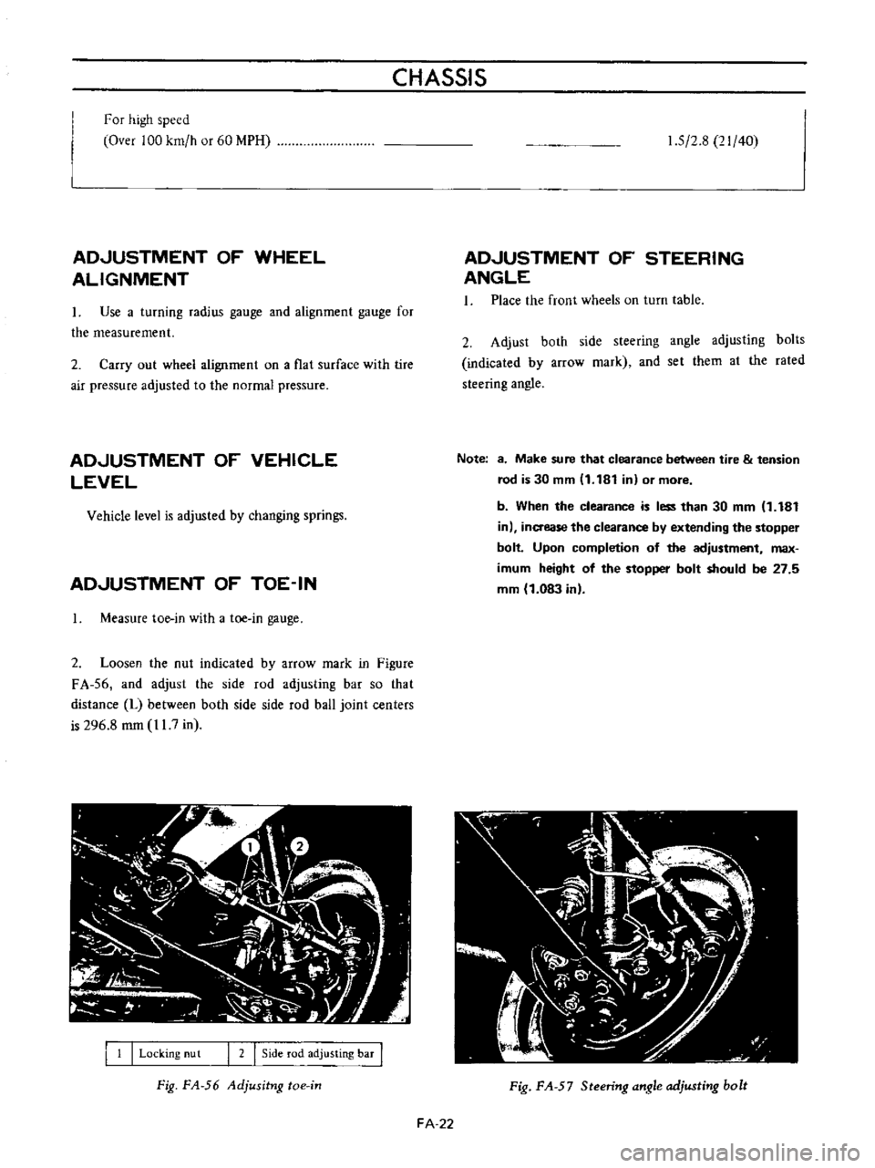
2
Loosen
the
nut
indicated
by
arrow
mark
in
Figure
FA
56
and
adjust
the
side
rod
adjusting
bar
so
that
distance
L
between
both
side
side
rod
ball
joint
centers
is
296
8
mm
11
7
in
I
1
I
Locking
nu
t
I
2
I
Side
rod
adjusting
bar
I
Fig
FA
56
Adjusitng
toe
in
1
5
2
8
21
40
ADJUSTMENT
OF
STEERING
ANGLE
1
Place
the
front
wheels
on
turn
table
2
Adjust
both
side
steering
angle
adjusting
bolts
indicated
by
arrow
mark
and
set
them
al
the
rated
steering
angle
Note
8
Make
sure
that
clearance
between
tire
tension
rod
is
30
mm
11
181
in
or
more
b
When
the
clearance
is
less
than
30
mm
1
181
in
inaease
the
clearance
by
extending
the
stopper
bolt
Upon
completion
of
the
adjustment
max
imum
height
of
the
stopper
bolt
should
be
27
5
mm
1
083
in
Fig
FA
57
Steering
angle
adjusting
bolt
FA
22
Page 109 of 513
FRONT
AXLE
FRONT
SUSPENSION
SERVICE
DATA
AND
SPECIFICATIONS
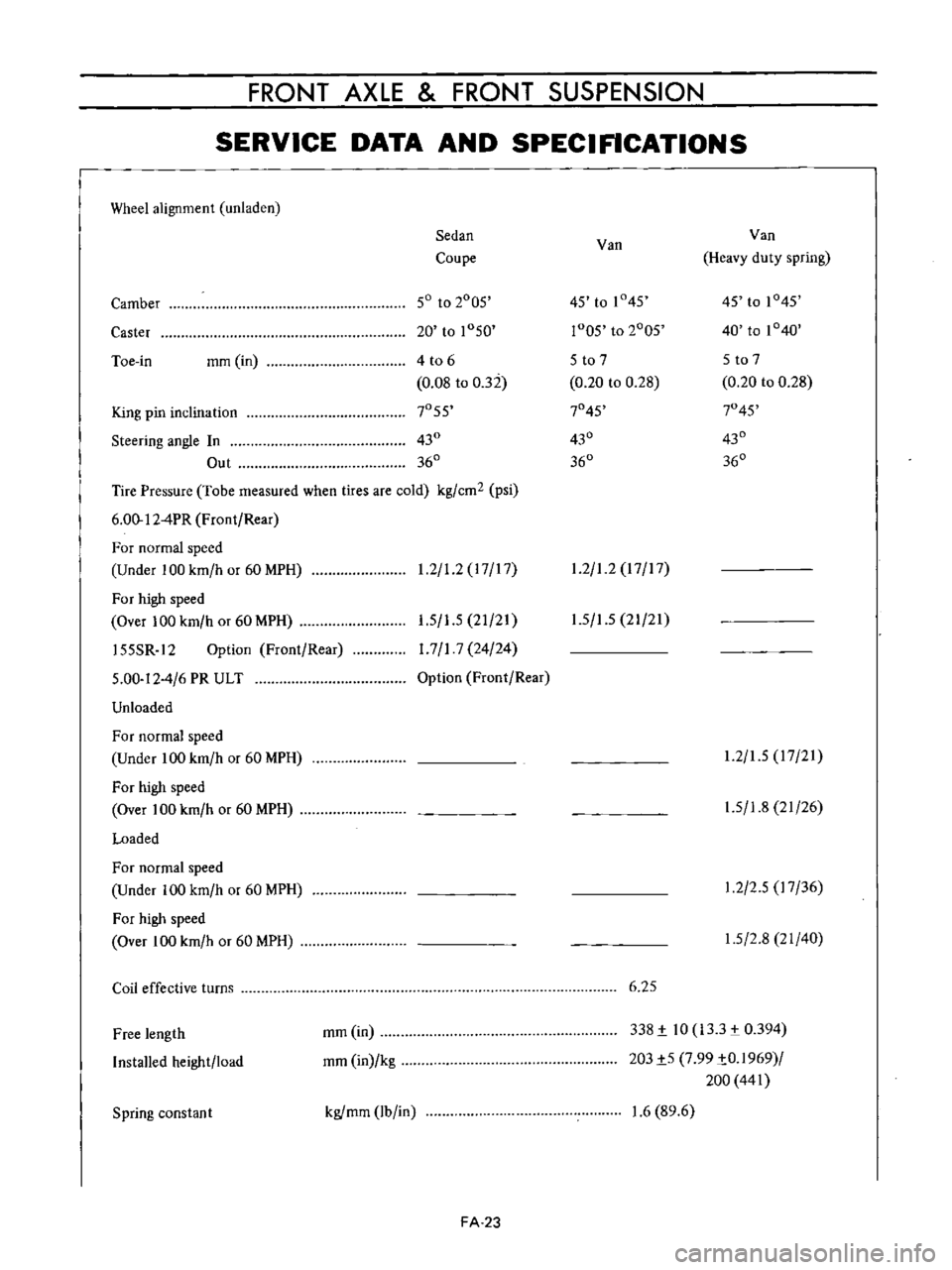
Wheel
alignment
unladen
Sedan
Van
Van
Coupe
Heavy
duty
spring
Camber
50
to
2005
45
to
1
45
45
to
1045
Caster
20
to
1050
r005
to
2005
40
to
1040
Toe
in
mm
in
4
t06
5
to
7
5
to
7
0
08
to
032
0
20
to
0
28
0
20
to
0
28
King
pin
inclination
7055
7045
7045
Steering
angle
In
430
430
430
Out
360
360
360
Tire
Pressure
Tobe
measured
when
tires
are
cold
kg
cm2
psi
6
00
12
4PR
Front
Rear
For
normal
speed
Under
100
km
h
or
60
MPH
1
2
1
2
17
17
1
2
1
2
17
17
For
high
speed
Over
100
km
h
or
60
MPH
155SR
12
Option
Front
Rear
5
00
12
4
6
PR
ULT
Unloaded
1
5
1
5
21
21
1
7
1
7
24
24
Option
Front
Rear
1
5
1
5
21
21
For
normal
speed
Under
100
km
h
or
60
MPH
For
high
speed
Over
100
km
h
or
60
MPH
Loaded
1
2
1
5
17
21
1
5
1
8
21
26
For
normal
speed
Under
100
km
h
or
60
MPH
For
high
speed
Over
100
km
h
or
60
MPH
1
2
2
5
17
36
1
5
2
8
21
40
Coil
effective
turns
6
25
Free
length
Installed
height
load
mm
in
mm
in
kg
338
i
10
133
0394
203i5
7
99
iO
1969
200
441
Spring
constan
t
kgfmm
lb
in
1
6
89
6
FA
23
Page 111 of 513
FRONT
AXLE
FRONT
SUSPENSION
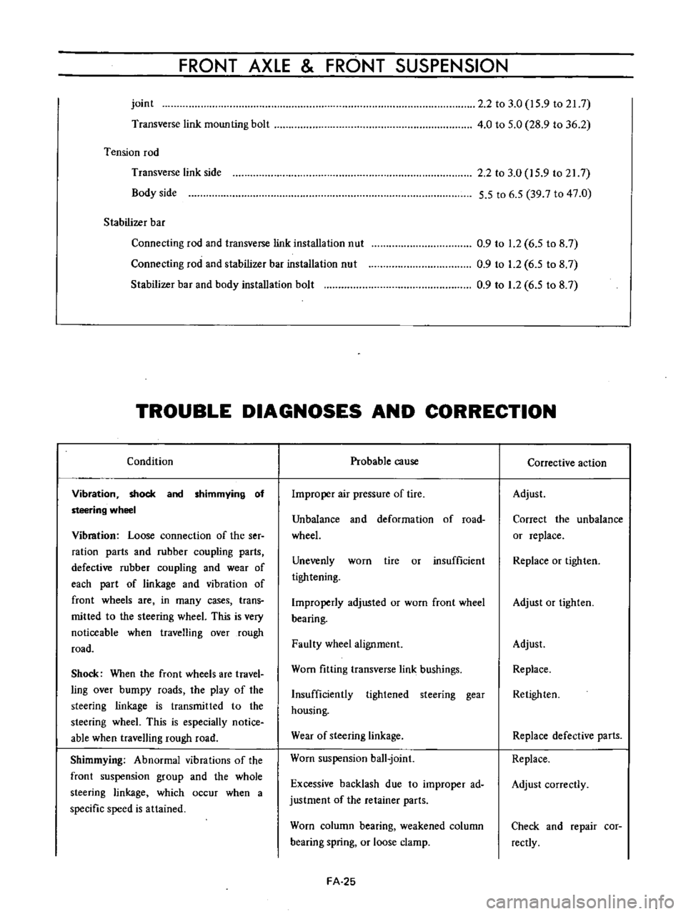
joint
Transverse
link
mounting
bolt
Tension
rod
Transverse
link
side
Body
side
Stabilizer
bar
Connecting
rod
and
transverse
link
installation
nut
Connecting
rod
and
stabilizer
bar
installation
nut
Stabilizer
bar
and
body
installation
bolt
2
2
to
3
0
15
9
to
21
7
4
0
to
5
0
28
9
to
36
2
2
2
to
3
0
15
9
to
217
5
5
to
6
5
39
7
to
47
0
0
9
to
1
2
6
5
to
8
7
0
9
to
1
2
6
5
to
8
7
0
9
to
1
2
6
5
to
8
7
TROUBLE
DIAGNOSES
AND
CORRECTION
Condition
Vibration
shock
and
shimmying
of
steering
wheel
Vibmtion
Loose
connection
of
the
ser
ration
parts
and
rubber
coupling
parts
defective
rubber
coupling
and
wear
of
each
part
of
linkage
and
vibration
of
front
wheels
are
in
many
cases
trans
mitted
to
the
steering
wheeL
This
is
very
noticeable
when
travelling
over
rough
road
Shock
When
the
front
wheels
are
travel
ling
over
bumpy
roads
the
play
of
the
steering
linkage
is
transmitted
to
the
steering
wheeL
This
is
especially
notice
able
when
travelling
rough
road
Shimmying
Abnormal
vibrations
of
the
front
suspension
group
and
the
whole
steering
linkage
which
occur
when
a
specific
speed
is
attained
Probable
cause
Improper
air
pressure
of
tire
Unbalance
and
deformation
of
road
wheeL
Unevenly
worn
tire
or
insufficient
tightening
Improperly
adjusted
or
worn
front
wheel
bearing
Faulty
wheel
alignment
Worn
fitting
transverse
link
bushings
Insufficiently
tightened
steering
gear
housing
Wear
of
steering
linkage
Worn
suspension
ball
joint
Excessive
backlash
due
to
improper
ad
justment
of
the
retainer
parts
Worn
column
bearing
weakened
column
bearing
spring
or
loose
clamp
FA
25
Corrective
action
Adjust
Correct
the
unbalance
or
replace
Replace
or
tighten
Adjust
or
tighten
Adjust
Replace
Retighten
Replace
defective
parts
Replace
Adjust
correctly
Check
and
repair
cor
rectly
Page 112 of 513
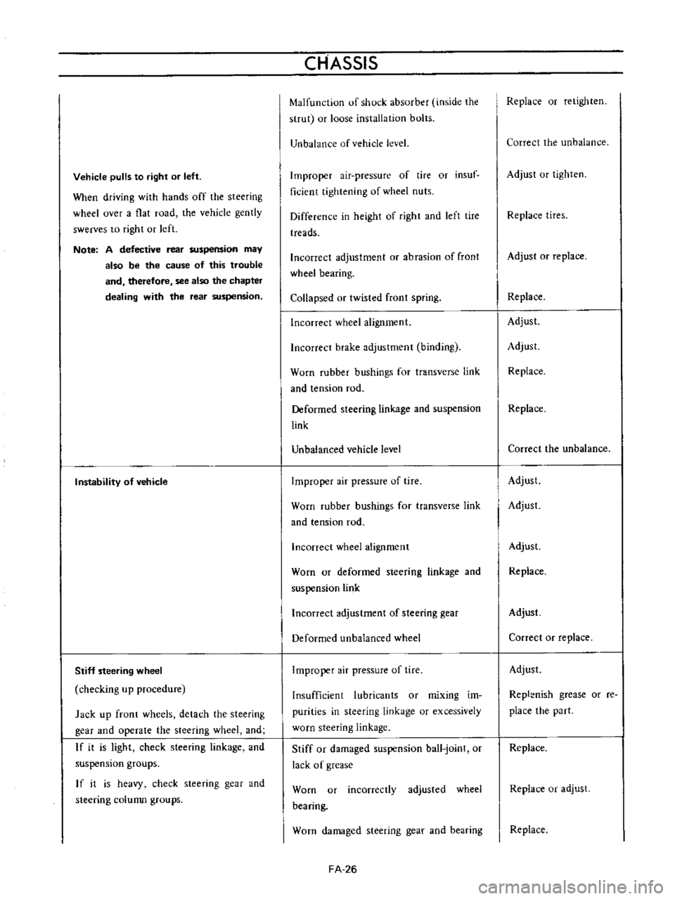
Vehicle
pulls
to
right
or
left
When
driving
with
hands
off
the
steering
wheel
over
a
flat
road
the
vehicle
gently
swerves
to
right
or
left
Note
A
defective
rear
suspension
may
also
be
the
cause
of
this
trouble
and
therefore
see
also
the
chapter
dealing
with
the
rear
suspension
Instability
of
vehicle
Stiff
steering
wheel
checking
up
procedure
Jack
up
front
wheels
detach
the
steering
gear
and
operate
the
steering
wheel
and
If
it
is
light
check
steering
linkage
and
suspension
groups
If
it
is
heavy
check
steering
gear
and
steering
colunm
groups
CHASSIS
Malfunction
of
shock
absorber
inside
the
strut
or
loose
installation
bolts
Unbalance
of
vehicle
level
Improper
air
pressure
of
tire
or
insuf
ficient
tightening
of
wheel
nuts
Difference
in
height
of
right
and
left
tire
treads
Incorrect
adjustment
or
abrasion
of
front
wheel
bearing
Collapsed
or
twisted
front
spring
Incorrect
wheel
alignment
Incorrect
brake
adjustment
binding
Worn
rubber
bushings
for
transverse
link
and
tension
rod
Deformed
steering
linkage
and
suspension
link
Unbalanced
vehicle
level
Improper
air
pressure
of
tire
Worn
rubber
bushings
for
transverse
link
and
tension
rod
Incorrect
wheel
alignment
Worn
or
deformed
steering
linkage
and
suspension
link
Incorrect
adjustment
of
steering
gear
Deformed
unbalanced
wheel
Improper
air
pressure
of
tire
Insufficient
lubricants
or
mixing
im
purities
in
steering
linkage
or
excessively
worn
steering
linkage
Stiff
or
damaged
suspension
ball
joint
or
lack
of
grease
Worn
or
incorrectly
adjusted
wheel
bearing
Worn
damaged
steering
gear
and
bearing
FA
26
Replace
or
retighten
Correct
the
unbalance
Adjust
or
tighten
Replace
tires
Adjust
or
replace
Replace
Adjust
Adjust
Replace
Replace
Correct
the
unbalance
Adjust
Adjust
Adjust
Replace
Adjust
Correct
or
replace
Adjust
Repl
nish
grease
or
re
place
the
part
Replace
Replace
or
adjust
Replace
Page 113 of 513
FRONT
AXLE
FRONT
SUSPENSION
Incorrectly
adjusted
steering
gear
Deformed
steering
linkage
Incorrect
wheel
alignment
Damaged
strut
upper
end
bearing
Damaged
or
stiff
piston
or
shock
absorber
rod
in
the
strut
Interference
of
steering
column
with
turn
signal
switch
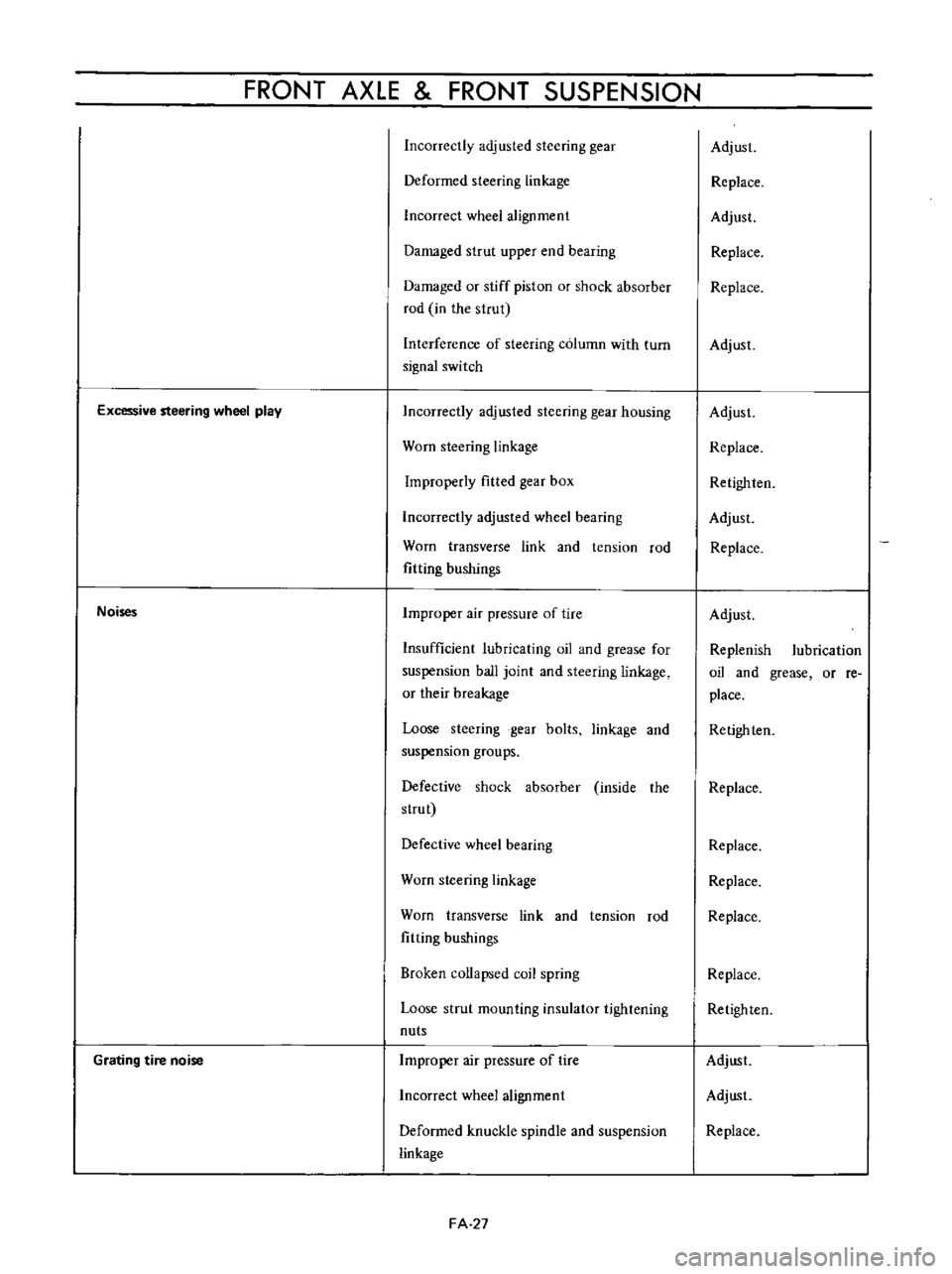
Excessive
steering
wheel
play
Noises
Grating
tire
noise
Incorrectly
adjusted
steering
gear
housing
Worn
steering
linkage
Improperly
fitted
gear
box
Incorrectly
adjusted
wheel
bearing
Worn
transverse
link
and
tension
rod
fitting
bushings
Improper
air
pressure
of
tire
Insufficient
lubricating
oil
and
grease
for
suspension
ball
joint
and
steering
linkage
or
their
breakage
Loose
steering
gear
bolts
linkage
and
suspension
groups
Defective
shock
absorber
inside
the
strut
Defective
wheel
bearing
Worn
steering
linkage
Worn
transverse
link
and
tension
rod
fitting
bushings
Broken
collapsed
coil
spring
Loose
strut
mounting
insulator
tightening
nuts
Improper
air
pressure
of
tire
Incorrect
wheel
alignment
Deformed
knuckle
spindle
and
suspension
linkage
FA
27
Adjust
Replace
Adjust
Replace
Replace
Adjust
Adjust
Replace
Retighlen
Adjust
Replace
Adjust
Replenish
lubrication
oil
and
grease
or
re
place
Retighten
Replace
Replace
Replace
Replace
Replace
Retighten
Adjust
Adjust
Replace
Page 126 of 513
CHASSIS
DESCRIPTION
The
Datsun
1200
series
new
models
adopt
a
hydraulic
brake
Dis
brake
or
two
leading
shoe
type
drum
brake
is
used
for
the
front
wheels
and
leading
trailing
shoe
type
drum
brake
is
used
for
the
rear
wheels
With
adoption
of
the
disc
brake
safety
at
high
speed
range
driving
is
further
improved
For
the
master
cylinder
either
single
type
or
tandem
type
is
used
There
are
two
types
of
tandem
type
master
cylinder
one
is
for
disc
brake
and
the
other
for
drum
brake
Under
the
standard
specifications
h0wever
the
tandem
type
master
cylinder
is
used
for
disc
brake
and
single
type
is
used
for
drum
brake
The
tandem
master
cylinder
provides
a
dual
brake
system
improving
safety
The
hand
brake
is
of
a
mechanical
type
which
brakes
the
rear
wheels
through
the
control
lever
and
steel
wire
The
control
lever
is
located
between
the
driver
and
assistant
seats
and
can
be
operated
easily
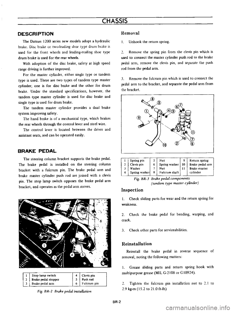
BRAKE
PEDAL
The
steering
colunm
bracket
supports
the
brake
pedaL
The
brake
pedal
is
instaUed
on
the
steering
column
bracket
with
a
fulcrum
pin
The
brake
pedal
arm
and
brake
master
cylinder
push
rod
are
joined
with
a
clevis
pin
The
stop
lamp
switch
opposes
the
brake
pedal
arm
bracket
and
operates
as
the
pedal
arm
moves
t
2
3
Stop
lamp
switch
Brake
pedal
stopper
Brake
pedal
arm
4
Clevis
pin
5
Push
rod
6
Fulcrum
pin
Fig
BR
2
Brake
pedal
installation
Removal
Unhook
the
rerum
spring
Remove
the
spring
pin
from
the
clevis
pin
which
is
used
to
connect
the
master
cylinder
push
rod
to
the
brake
pedal
arm
remove
the
clevis
pin
and
separate
the
push
rod
from
the
pedal
arm
3
Remove
the
fulcrum
pin
which
is
used
to
connect
the
pedal
arm
to
the
bracket
and
separate
the
pedal
arm
from
the
bracket
@
mm
l6
qf
@
@
t
Spring
pin
5
Nut
9
Return
spring
2
Clevis
pin
6
Spring
washer
10
Brake
pedal
arm
3
Washer
7
Nut
It
Brake
master
4
Spring
lasher
8
Fulcrum
shaft
cylinder
Fig
BR
3
Brake
pedal
components
tandem
type
master
cylinder
Inspection
1
Check
sliding
parts
for
wear
and
the
return
spring
for
weakness
2
Check
the
brake
pedal
for
bending
warping
and
crack
3
Check
other
parts
for
serviceabilities
Reinstallation
Reinstall
the
brake
pedal
in
reverse
sequence
of
removal
noting
the
following
matters
1
Grease
sliding
parts
and
retum
spring
hook
with
multipurpose
grease
MIL
G
2108
or
G
10924
2
Tighten
the
fulcrum
pin
installation
nut
to
2
1
to
2
9
kg
m
15
2
to
21
0
ft
lb
BR
2