1973 DATSUN B110 steering wheel
[x] Cancel search: steering wheelPage 172 of 513
CHASSIS
The
sliding
block
is
secured
on
the
steering
post
bracket
with
bolts
upper
half
of
the
steering
column
is
supported
on
the
bracket
and
thus
the
steering
post
clamp
is
installed
on
the
body
When
a
large
impact
is
applied
from
the
driver
side
the
plastic
pins
are
cut
off
and
leaving
the
sliding
block
in
the
steering
post
bracket
side
the
clamp
proper
is
disengaged
downward
together
with
the
jacket
tube
For
any
force
applied
from
front
direction
of
the
vehicle
the
steering
post
clamp
sliding
block
does
not
move
rearward
This
construction
is
called
One
way
slide
system
and
with
this
construction
projection
of
the
column
shaft
toward
the
driver
is
prevented
completely
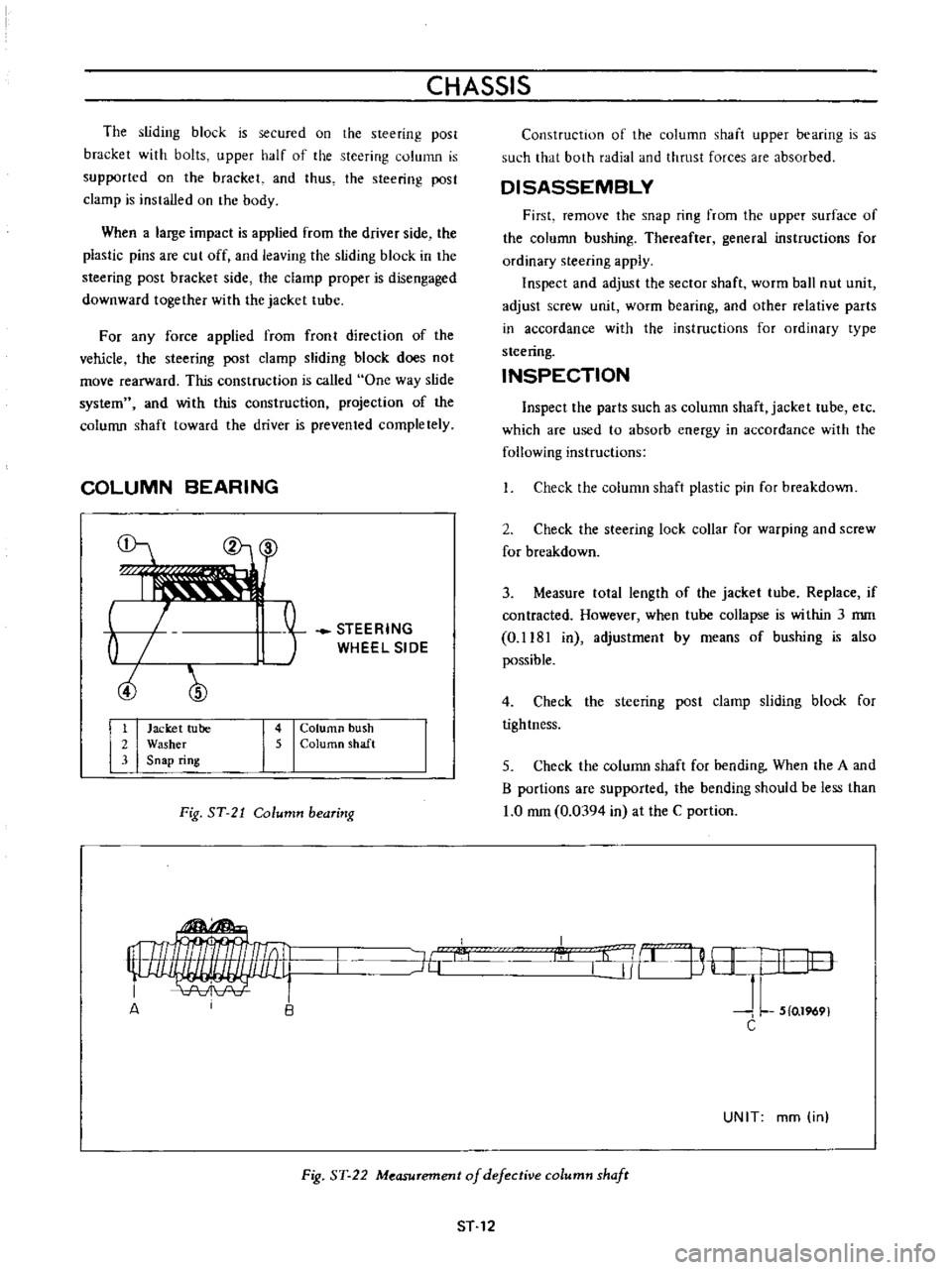
COLUMN
BEARING
b
ciJ
STEERING
WHEEL
SIDE
1
Jacket
tube
2
Washer
3
Snap
ring
4
Column
bush
5
ColurtlO
shaft
Fig
ST
21
Column
bearing
Construction
of
the
column
shaft
upper
bearing
is
as
such
that
both
radial
and
thrust
forces
are
absorbed
DISASSEMBLY
First
remove
the
snap
ring
from
the
upper
surface
of
the
column
bushing
Thereafter
general
instructions
for
ordinary
steering
apply
Inspect
and
adjust
the
sector
shaft
worm
ball
nut
unit
adjust
screw
unit
worm
bearing
and
other
relative
parts
in
accordance
with
the
instructions
for
ordinary
type
steering
INSPECTION
Inspect
the
parts
such
as
column
shaft
jacket
tube
etc
which
are
used
to
absorb
energy
in
accordance
with
the
following
instructions
Check
the
column
shaft
plastic
pin
for
breakdown
2
Check
the
steering
lock
collar
for
warping
and
screw
for
breakdown
3
Measure
tolal
length
of
the
jacket
tube
Replace
if
contracted
However
when
tube
collapse
is
within
3
mm
0
1181
in
adjustmenl
by
means
of
bushing
is
also
possible
4
Check
the
steering
post
clamp
sliding
block
for
tightness
5
Check
the
column
shaft
for
bending
When
the
A
and
B
portions
are
supported
the
bending
should
be
less
than
1
0
mm
0
0394
in
at
the
C
portion
I
l
j
B
H
I
I
lO
J
L
5
0
1969
C
J6
A
UNIT
mm
in
Fig
ST
22
Measurement
of
defective
column
shafr
ST
12
Page 176 of 513
CHASSIS
The
following
tightening
torque
of
nuts
shall
be
adopted
Ball
stud
nut
3
0
to
5
0
kg
m
21
7
to
36
2
ft
lb
Gear
arm
nut
14
kg
m
101
ft
lb
Idler
arm
nut
57
to
6
3
kg
m
41
2
to
45
6
ft
lb
2
Assembly
of
the
idler
assembly
is
accomplished
as
follows
I
Apply
soap
water
on
the
outer
circumference
of
bushing
Press
the
bushing
into
the
idler
arm
carefully
until
the
bushing
protrudes
equally
at
the
both
sides
2
Fit
idler
arm
body
in
the
rubber
bushing
Keep
the
idler
arm
center
line
in
parallel
with
the
chassis
center
line
INSTALLATION
Installation
can
be
accomplished
in
the
reverse
order
of
removal
Pay
attention
to
the
following
points
Set
the
length
of
both
side
rods
to
296
8
mm
11
69
in
It
should
be
done
between
the
ball
stud
centers
2
Check
wheel
alignment
and
if
necessary
adjust
it
ACCIDENT
COLLISION
When
accident
collision
occurs
unfortunately
and
the
vehicle
especially
its
front
unit
is
damaged
conduct
inspection
in
accordance
with
the
following
instruction
Inspect
the
steering
system
particularly
carefully
because
it
is
a
very
important
unit
for
driving
I
Check
both
side
steering
angles
for
correct
balance
2
With
the
tires
positioned
at
neutral
steering
wheel
bar
for
correct
position
check
the
l
3
Operate
the
steering
system
and
check
it
for
sliding
noise
4
Check
the
operation
for
smoothness
l
5
Check
the
side
rod
and
cross
rod
for
bending
6
Check
the
gear
arm
for
crack
7
Check
the
gear
housing
tiglltening
bolt
for
slackness
and
installation
boss
for
crack
8
Check
the
sector
shaft
serration
for
twisting
9
Check
the
sector
gear
for
crack
10
Check
the
ball
screw
for
pitting
II
Check
the
column
shaft
for
bending
crack
and
sliding
scar
12
Check
the
jacket
tube
for
bending
13
Check
the
steering
post
clamp
for
existance
of
column
offset
14
Check
the
side
member
gear
housing
installation
unit
for
deformation
IS
Check
the
portion
of
the
steering
post
bracket
installed
on
the
steering
post
clamp
for
correct
installation
AD
JUSTMENT
I
Toe
in
The
procedure
of
toe
in
adjustment
is
outlined
in
section
FRONT
AXLE
AND
FRONT
SUSPENSION
2
Steering
angle
Under
the
specified
load
4
passengers
adjust
the
stopper
bolt
of
the
knuckle
arm
so
that
the
inner
wheel
has
an
angle
of
430
Note
Specified
steering
angle
of
wheel
is
430
for
inner
wheel
and
36005
for
outer
wheel
ST
16
Page 177 of 513
STEERING
SERVICE
DATA
AND
SPECIFICATIONS
Type
Gear
ratio
Steering
wheel
diameter
Oil
capacity
Steering
angle
inner
wheel
outer
wheel
Play
steering
wheel
Standard
thickness
of
worrn
bearing
shims
Initial
turning
torque
of
column
assembly
Clearance
of
adjusting
screw
to
sector
shaft
Length
of
side
rod
Tightening
torque
Steering
wheel
lock
nut
Steering
post
clamp
to
steering
post
bracket
bolls
Collapsible
Steering
column
hole
cover
bolts
Column
to
gear
housing
bolts
Side
cover
to
gear
housing
bolts
Adjusting
screw
lock
nut
Sector
shaft
to
pitman
arm
nut
Gear
housing
to
side
main
bar
bolts
and
nuts
Idler
arm
nut
Recirculating
ball
type
mm
in
L
US
pt
Imp
pt
15
I
I
400
157
0
24
I
2
3
8
430
360
mm
in
20
to
25
0
787
to
0
984
mm
in
0
5
0
0197
kg
em
in
oz
2
0
to
5
0
27
8
to
69
4
mrn
in
mm
in
0
05
0
0020
296
8
11
69
kg
m
ft
lb
3
0
to
3
5
217
to
25
3
kg
m
ft
lb
kg
m
ft
Ib
kg
m
ft
lb
kg
m
ft
lb
kg
m
ft
lb
kg
m
ft
lb
kg
m
ft
lb
0
8
to
1
0
5
8
to
7
2
1
5
to
1
8
10
8
to
13
0
8
to
1
0
5
8
to
7
2
1
5
to
2
5
10
8
to
18
1
I
7
to
2
8
12
3
to
20
2
2
0
to
3
0
14
5
to
21
7
14
101
kg
m
ft
lb
kg
m
ft
lb
1
9
to
2
6
13
7
to
18
8
57
to
6
3
41
2
to
45
6
Idler
arm
to
side
main
bar
bolts
and
nuts
kg
m
ft
Ib
Ball
stud
nuts
kg
m
ft
lb
Side
rod
bar
lock
nuts
kg
m
ft
lb
1
9
to
2
6
13
7
to
18
8
3
0
to
5
0
21
7
to
36
2
8
0
to
10
0
57
8
to
72
3
ST
17
Page 178 of 513
CHASSIS
TROUBLE
DIAGNOSES
AND
CORRECTIONS
Condition
Heavy
steering
Loose
steering
PuU
to
one
side
Steering
shock
Probable
cause
Low
tire
pressure
Incorrect
front
wheel
alignment
Lack
of
lubricant
Firm
sticking
of
the
ball
joint
and
strut
bearing
Improper
adjustment
and
damage
of
steering
gear
housing
Hard
locking
of
column
bearing
Incorrect
front
wheel
bearing
adjustment
Loose
steering
linkage
connections
Loose
steering
gear
housing
mounting
Incorrect
adjustment
of
adjust
nut
Incorrect
tire
pressure
Incorrect
front
wheel
alignment
Incorrect
front
wheel
bearing
adjustment
Unequal
brake
adjustment
Weak
front
suspension
units
Deformation
or
improper
fitting
of
sus
pension
Incorrect
front
wheel
alignment
Loose
front
wheel
bearings
Loose
steering
linkage
connection
and
trans
verse
link
Incorrect
adjustment
of
ball
nut
Wheels
out
of
balance
ST
18
Corrective
action
Inflate
tires
to
recommended
pressure
Adjust
to
specifications
Lubricate
steering
gear
and
ball
joints
or
replace
worn
ball
joint
Replace
Adjust
or
replace
according
to
instructions
Lubricate
with
bearing
grease
Adjust
or
replace
as
required
Inspect
replace
worn
parts
if
any
and
tighten
nuts
to
recommended
torque
Tighten
mounting
bolts
to
proper
torque
Adjust
according
to
instructions
Inflate
to
recommended
pressure
Inspect
and
correct
front
wheel
alignment
Adjust
bearings
according
to
instructions
Adjust
brakes
Replace
Check
correct
or
replace
Inspect
and
correct
front
wheel
alignment
Adjust
bearings
Inspect
replace
worn
parts
if
any
and
tighten
nuts
to
proper
torque
Adjust
steering
gear
according
to
in
structions
Inspect
and
correct
wheel
balance
Page 232 of 513

BODY
INSTRUMENT
PANEL
CONTENTS
REMOVAL
BF
42
REMOVAL
Fig
BF
88
Removing
instrument
panel
Note
There
are
two
types
of
instrument
panel
square
type
and
round
type
However
both
of
them
are
removed
and
reinstalled
in
the
same
manner
Disconnect
the
battery
cable
at
the
battery
terminal
2
Disconnect
the
wiring
harness
connector
units
Disconnect
the
instrument
harness
from
the
engine
compartment
harness
Disconnect
the
instrument
harness
from
the
turn
signal
switch
Disconnect
the
instrument
harness
frorn
the
body
harness
Disconnect
the
instrumen
t
harness
connected
to
the
door
switch
stop
lamp
switch
flasher
unit
and
passing
light
relay
option
REINSTALLATION
BF
43
Note
When
disconnecting
the
wiring
harness
recom
mend
to
use
tags
for
identifying
their
relationship
3
Disconnect
cables
for
radio
antenna
and
speaker
4
Remove
the
package
tray
the
shell
cover
and
turn
signal
switch
Note
Work
may
be
carried
out
without
removing
die
steering
wheel
However
it
is
recommended
to
remove
the
steering
wheel
50
that
work
can
be
carried
out
more
easily
5
Disconnect
the
speedometer
cable
from
the
speedometer
unit
6
Disconnect
the
heater
control
cable
at
the
heater
side
Fig
BF
89
Removing
imtrument
panel
Ii
BF
42
Page 245 of 513
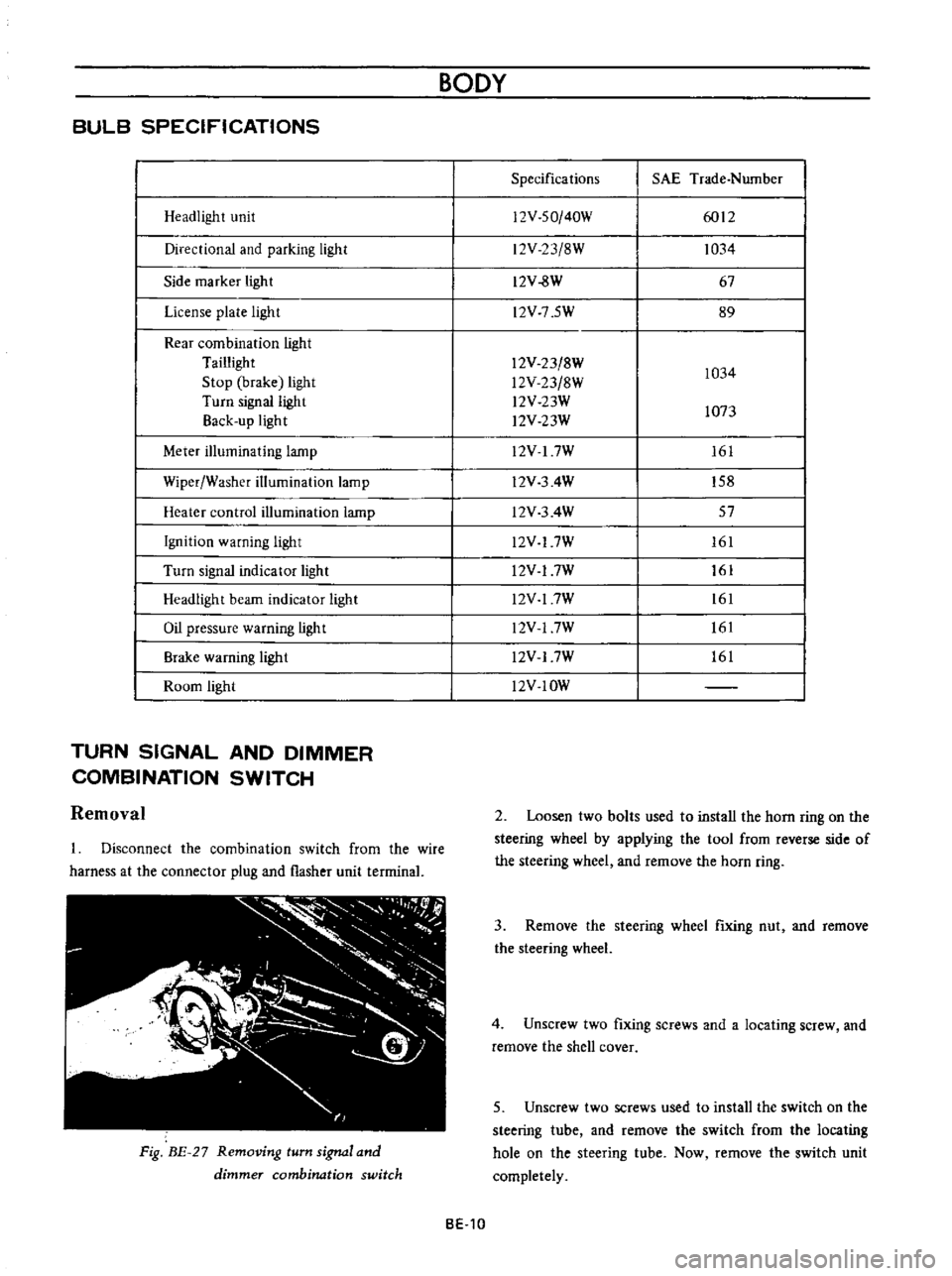
BULB
SPECIFICATIONS
Headlight
unit
Directional
and
parking
light
Side
marker
light
License
plate
light
Rear
combination
light
Taillight
Stop
brake
light
Turn
signal
light
Back
up
light
Meter
illuminating
lamp
Wiper
Washer
illumination
lamp
Heater
control
illumination
lamp
Ignition
warning
light
Turn
signal
indicator
light
Headlight
beam
indicator
light
Oil
pressure
warning
light
Brake
warning
ligh
t
Room
light
TURN
SIGNAL
AND
DIMMER
COMBINATION
SWITCH
Removal
Disconnect
the
combination
switch
from
the
wire
harness
at
the
connector
plug
and
flasher
unit
terrninal
Fig
BE
27
Removing
turn
signal
and
dimmer
combination
switch
BODY
Specifications
SAE
Trade
Number
12V
SO
40W
6012
12V
23
8W
1034
12V
8W
67
l2V
7
5W
89
12V
23
8W
1034
l2V
23
8W
l2V
23W
1073
l2V
23W
12V
I
7W
161
l2V
3
4W
158
l2V
3
4W
57
l2V
17W
161
l2V
17W
161
l2V
17W
161
l2V
17W
161
l2V
17W
161
l2V
IOW
2
Loosen
two
bolts
used
to
install
the
horn
ring
on
the
steering
wheel
by
applying
the
tool
from
reverse
side
of
the
steering
wheel
and
remove
the
horn
ring
3
Remove
the
steering
wheel
fixing
nut
and
remove
the
steering
wheel
4
Unscrew
two
fixing
screws
and
a
locating
screw
and
remove
the
shell
cover
5
Unscrew
two
screws
used
to
install
the
switch
on
the
steering
tube
and
remove
the
switch
from
the
locating
hole
on
the
steering
tube
Now
remove
the
switch
unit
completely
BE
10
Page 265 of 513

mechanism
is
installed
on
the
steering
jacket
tube
When
the
key
is
set
to
Lock
position
and
removed
the
steering
lock
spindle
is
inserted
in
a
notch
in
the
collar
which
is
stationarity
set
on
the
steering
shaft
to
lock
the
steering
wheel
The
ignitiun
switch
is
installed
on
the
back
of
key
cylinder
with
a
attaching
screw
and
interchangeable
tf
iY
t
7
a
1
Ignition
switch
part
2
Key
cylinder
part
3
Steering
jacket
tube
4
Lock
collar
5
Lock
pindle
6
Steering
shaft
7
Self
shear
type
screw
8
Attaching
screw
Fig
BE
50
Steering
lock
Key
position
Terminal
OFFor
GARAGE
Lock
ON
ST
ART
B
Battery
IG
Ignition
S
Starter
R
Resistance
b
1
Steering
lock
replacement
For
the
purpuse
of
tamper
proof
the
self
shear
type
screws
are
used
and
their
heads
are
sheared
off
when
installed
so
that
the
steering
lock
system
cannot
be
removed
easily
Replace
the
steering
lock
proper
in
accordance
with
the
following
instructions
when
required
Loosen
two
attaching
screws
and
break
the
remaining
twu
self
shear
type
screws
with
a
drill
or
other
proper
tool
Now
remove
the
steering
lock
proper
from
the
BODY
BE
30
steering
jacket
tube
When
installing
a
new
steering
lock
proper
be
sure
tu
tighten
two
new
self
shear
type
screws
to
shear
off
their
heads
Warning
switch
and
warnmg
buzzer
Fig
BE
51
Warning
switch
The
circuit
of
this
warning
system
is
closed
when
the
door
is
opened
with
the
steering
unlocked
because
the
door
switch
and
warning
switch
are
connected
in
series
When
the
cicuit
is
closed
the
buzzer
sounds
When
replacing
the
warning
switch
disconnect
two
cables
remove
the
cap
loosen
two
attaching
screws
and
remove
the
warning
switch
The
warning
buzzer
is
installed
on
the
back
left
side
of
the
instrument
panel
with
two
attaching
screws
FUSE
WARNING
SWITCH
WARN
BUZZ
G
n
WITCH
t
Fig
BE
52
Circuit
diagram
for
warning
system
Page 286 of 513
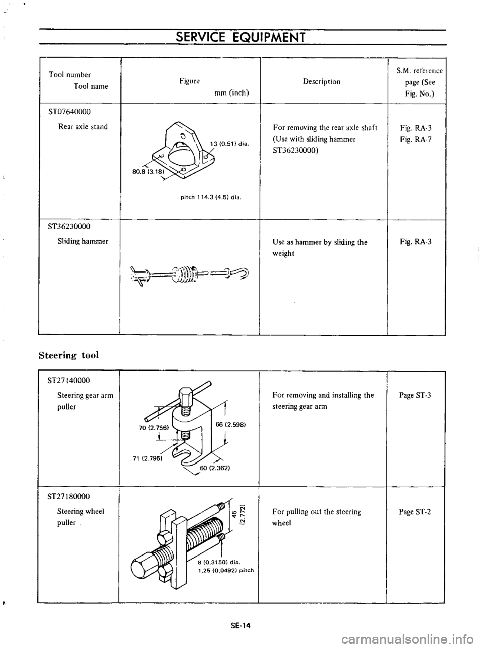
Tool
number
Tool
name
ST07640000
Rear
axle
stand
ST36230000
Sliding
hammer
Steering
tool
ST27140000
Steering
gear
arm
puller
ST27
I
80000
Steering
wheel
puller
SERVICE
EQUIPMENT
Figure
mm
inch
pitch
114
3
4
51
dia
J
l
VJJJJ1
P
J
SE
14
Description
For
removing
the
rear
axle
shaft
Use
with
sliding
hammer
ST36230000
Use
as
hammer
by
sliding
the
weight
For
removing
and
installIng
the
steering
gear
arm
For
pulling
out
the
steering
wheel
S
M
refelcTu
e
page
See
Fig
No
Fig
RA
3
Fig
RA
7
Fig
RA
3
Page
ST
3
Page
ST
2