1973 DATSUN B110 steering wheel
[x] Cancel search: steering wheelPage 155 of 513
CHASSIS
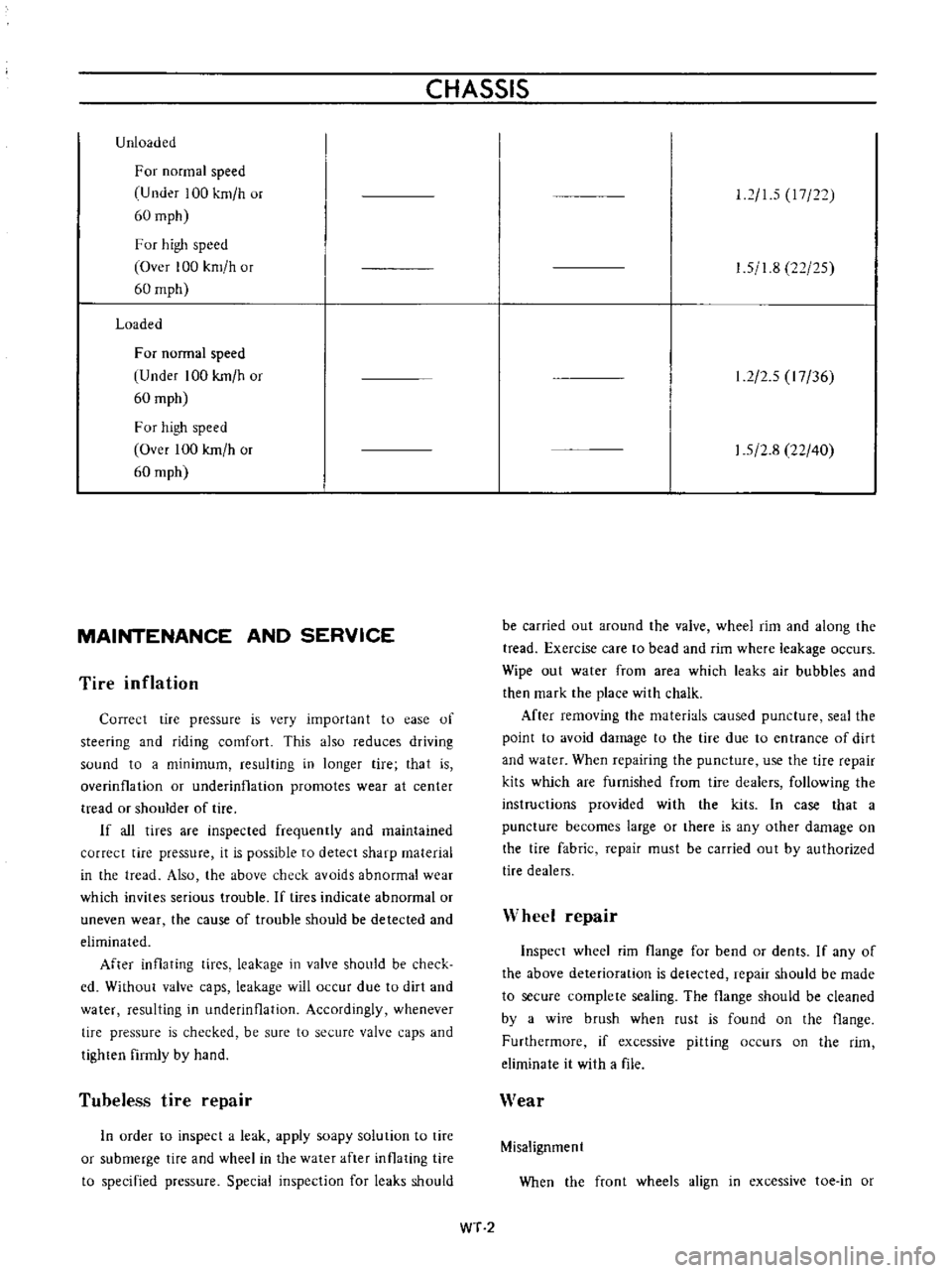
Unloaded
For
normal
speed
U
nder
100
km
h
or
60
mph
F
or
high
speed
Over
100
km
h
or
60
mph
Loaded
For
normal
speed
Under
100
kmlh
or
60
mph
For
high
speed
Over
100
kmlh
or
60
mph
MAINTENANCE
AND
SERVICE
Tire
inflation
Correct
tire
pressure
is
very
importan
t
to
ease
of
steering
and
riding
comfort
This
also
reduces
driving
sound
to
a
minimum
resulting
in
longer
tire
that
is
overinfla
lion
or
underinflation
promotes
wear
at
center
tread
or
shoulder
of
tire
If
all
tires
are
inspected
frequently
and
maintained
correct
tire
pressure
it
is
possible
to
detect
sharp
material
in
the
tread
Also
the
above
check
avoids
abnormal
wear
which
invites
serious
trouble
If
tires
indicate
abnormal
or
uneven
wear
the
cause
of
trouble
should
be
detected
and
eliminated
After
inflating
tices
leakage
in
valve
should
be
check
cd
Without
valve
caps
leakage
will
occur
due
to
dirt
and
water
resulting
in
underinOation
Accordingly
whenever
tire
pressure
is
checked
be
sure
to
secure
valve
caps
and
tighten
firmly
by
hand
Tubeless
tire
repair
In
urder
to
inspect
a
leak
apply
soapy
solution
to
tire
or
submerge
tire
and
wheel
in
the
water
after
inflating
tire
to
specified
pressure
Special
inspection
for
leaks
should
12
15
17
22
1
5
1
8
22
25
1
2
2
5
I
7
36
1
5
2
8
22
40
be
carried
out
around
the
valve
wheel
rim
and
along
the
tread
Exercise
care
to
bead
and
rim
where
leakage
occurs
Wipe
out
water
from
area
which
leaks
air
bubbles
and
then
mark
the
place
with
chalk
After
remuving
the
materials
caused
puncture
seal
the
point
to
avoid
damage
to
the
tire
due
to
entrance
of
dirt
and
water
When
repairing
the
puncture
use
the
tire
repair
kits
which
are
furnished
from
tire
dealers
following
the
instructions
provided
with
the
kits
In
case
that
a
puncture
becomes
large
or
there
is
any
other
damage
on
the
tire
fabric
repair
must
be
carried
out
by
authorized
tire
dealers
Wheel
repair
Inspect
wheel
rim
flange
for
bend
or
dents
If
any
of
the
above
deterioration
is
detected
repair
should
be
made
to
secure
complete
sealing
The
flange
should
be
cleaned
by
a
wire
brush
when
rust
is
found
on
the
flange
Furthermore
if
excessive
pitting
occurs
on
the
rim
eliminate
it
with
a
file
Wear
Misalignment
When
the
front
wheels
align
in
excessive
toe
in
or
WT
2
Page 157 of 513

CHASSIS
Tire
rotation
Tires
wear
unevenly
and
become
unbalanced
according
to
running
distance
Uneven
tire
wear
often
results
in
tire
noise
whkh
is
attributed
to
rear
axle
gears
bearing
ell
Meanwhile
the
front
tires
tend
to
wear
unevenly
because
of
front
wheel
alignment
Accordingly
to
equalize
tire
wear
it
is
necessary
to
rotate
tires
every
10
000
km
6
000
miles
of
operation
RIGHT
FRONT
RIGHT
REAR
r
1
Xl
L
J
LEFT
FRONT
LEFT
REAR
Fig
WT
2
Tire
rotation
The
tires
are
provided
with
tread
wear
indicator
at
six
places
around
tire
circumference
indicating
1
6
nun
0
16
in
tread
depth
When
the
tires
wear
and
then
the
marks
a
ppear
replace
them
with
new
ones
TREAD
WEAR
INDICATOR
7
TREAD
m
Y
X
W
X
v
w
WH024
Fig
WI
3
Tread
wear
illdicator
To
change
tire
with
wheel
using
a
jack
in
the
safe
manner
observe
the
following
procedures
I
Apply
parking
brake
and
block
front
wheels
when
rear
wheel
is
being
changed
2
Remove
wheel
cap
and
loosen
wheel
nuts
3
Place
jack
at
jacking
point
instructed
under
General
Information
and
raise
car
until
wheel
clears
ground
4
Remove
wheel
nuts
and
whed
from
drum
5
To
install
wheel
reverse
the
above
steps
Tighten
whed
nuts
in
criss
cross
fashion
to
8
0
to
9
0
kg
m
58
to
65
ft
lb
Note
Never
get
under
the
car
while
it
is
supported
only
by
the
jack
Always
use
safety
stands
to
support
the
side
member
of
body
construction
when
you
must
get
beneath
the
car
INSPECTION
Wheel
balance
The
wheel
and
tire
assembly
should
be
kept
balanced
statically
and
dynamically
Proper
tire
balance
is
necessary
when
driving
the
car
at
high
speeds
Consequently
the
wheel
and
tire
assembly
should
be
properly
rebalanced
whenever
puncture
is
repaired
The
wheel
and
tire
assembly
becomes
out
of
balance
according
to
uneven
tire
wear
Severe
acceleration
and
braking
or
fast
cornering
is
the
cause
of
wear
on
tire
resulting
in
unbalance
of
tire
and
wheel
assembly
The
symptom
of
unbalance
appears
as
tramp
car
shake
and
steering
trouble
To
correct
unbalance
use
proper
wheel
balancer
Maximum
allowable
unbalance
165
gr
cm
2
3
in
ol
at
rim
circumferences
Balance
weight
10
to
70
gr
0
35
to
2
47
Ol
at
10
gr
0
35
Ol
interval
Note
Be
sure
to
place
the
correct
balance
weights
on
the
inner
edge
of
rim
as
shown
in
Figure
WT
4
Wheel
and
tire
In
order
to
ensure
satisfactory
steering
condition
as
well
as
maximum
tire
life
proceed
as
follows
I
Check
wheel
rim
especially
rim
flange
and
bead
seat
for
rust
distortion
cracks
or
other
defects
which
might
cause
air
leaks
Function
of
tubeless
tire
depends
on
a
good
seal
between
tire
bead
and
wheel
rim
Thoroughly
remove
rust
dust
oxidized
rubber
or
sand
from
wheel
rim
with
wire
brush
emery
cloth
or
paper
Use
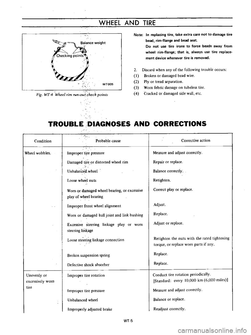
dial
gauge
to
examine
wheel
rim
for
lateral
and
diametral
run
out
WT
4
Page 158 of 513
WHEEL
AND
TIRE
Note
In
replacing
tire
take
extra
care
not
to
damage
tire
bead
rim
flange
and
bead
seat
Do
not
use
tire
irons
to
force
beads
away
from
wheel
rim
flange
that
is
always
use
tire
replace
ment
device
whenever
tire
is
removed
WT005
2
Discard
when
any
of
the
following
trouble
occurs
I
Broken
or
damaged
bead
wire
2
Ply
or
tread
separation
3
Worn
febric
damage
on
tubeless
tire
4
Cracked
or
damaged
side
wall
etc
Fig
WT
4
Wheel
rim
run
out
heck
points
TROUBLE
DIAGNOSES
AND
CORRECTIONS
Condition
Probable
cause
Corrective
action
Wheel
wobbles
Improper
t
re
pressure
Measure
and
adjust
correctly
Damaged
tire
9f
distorted
wheel
rim
Repair
or
replace
UnbalanceiLwheel
Balance
correctly
Loose
wheel
nuts
Retighten
Worn
qr
damaged
wheel
bearing
or
excessive
play
of
wheel
bearing
Correct
play
or
replace
Improper
front
wheel
alignment
Adjust
Worn
or
damaged
ball
joint
and
link
bushing
Replace
Excessive
steering
linkage
play
or
worn
steering
lin
age
Adjust
or
replace
Loose
stcerin
linkage
connection
Retighten
the
nuts
with
the
rated
lightening
torque
or
replace
worn
parts
if
any
Broken
suspension
spring
Replace
Defective
shock
absorber
Replace
Unevenly
or
excessively
worn
tire
Improper
tire
rotation
Conduct
tire
rotation
periodically
Standard
every
10
000
km
6
000
miies
Improper
tire
pressure
Measure
and
adjust
correctly
Unbalanced
wheel
Balance
or
replace
Improperly
adjusled
brake
Readjust
correctly
WT5
Page 161 of 513
STEERING
DESCRIPTION
The
steering
system
consists
of
recirculating
ball
type
gear
box
and
parallelogram
linkage
These
systems
give
good
response
light
handling
and
utmost
durability
Moreover
the
steering
linkage
is
equipped
with
a
torsion
rubber
system
idler
arm
which
absorbs
shock
from
the
wheel
Check
the
lubricant
of
gear
box
every
10
000
km
6
000
miles
and
replenish
recommended
oil
as
required
The
steering
linkage
should
be
greased
up
with
wheel
bearing
grease
every
50
000
km
30
000
miles
All
necessary
service
procedures
for
the
steering
lock
system
are
described
in
the
BODY
ELECTRICAL
SECTION
of
this
manual
and
therefore
no
instruction
is
given
here
STEERING
CONTENTS
REMOVAL
DISASSEMBL
Y
Ball
nut
assembly
ST
2
ST
3
ST
4
INSPECTION
AND
REPAIR
ASSEMBL
Y
AND
ADJUSTMENT
INSTALLATION
ST
4
ST
5
ST
7
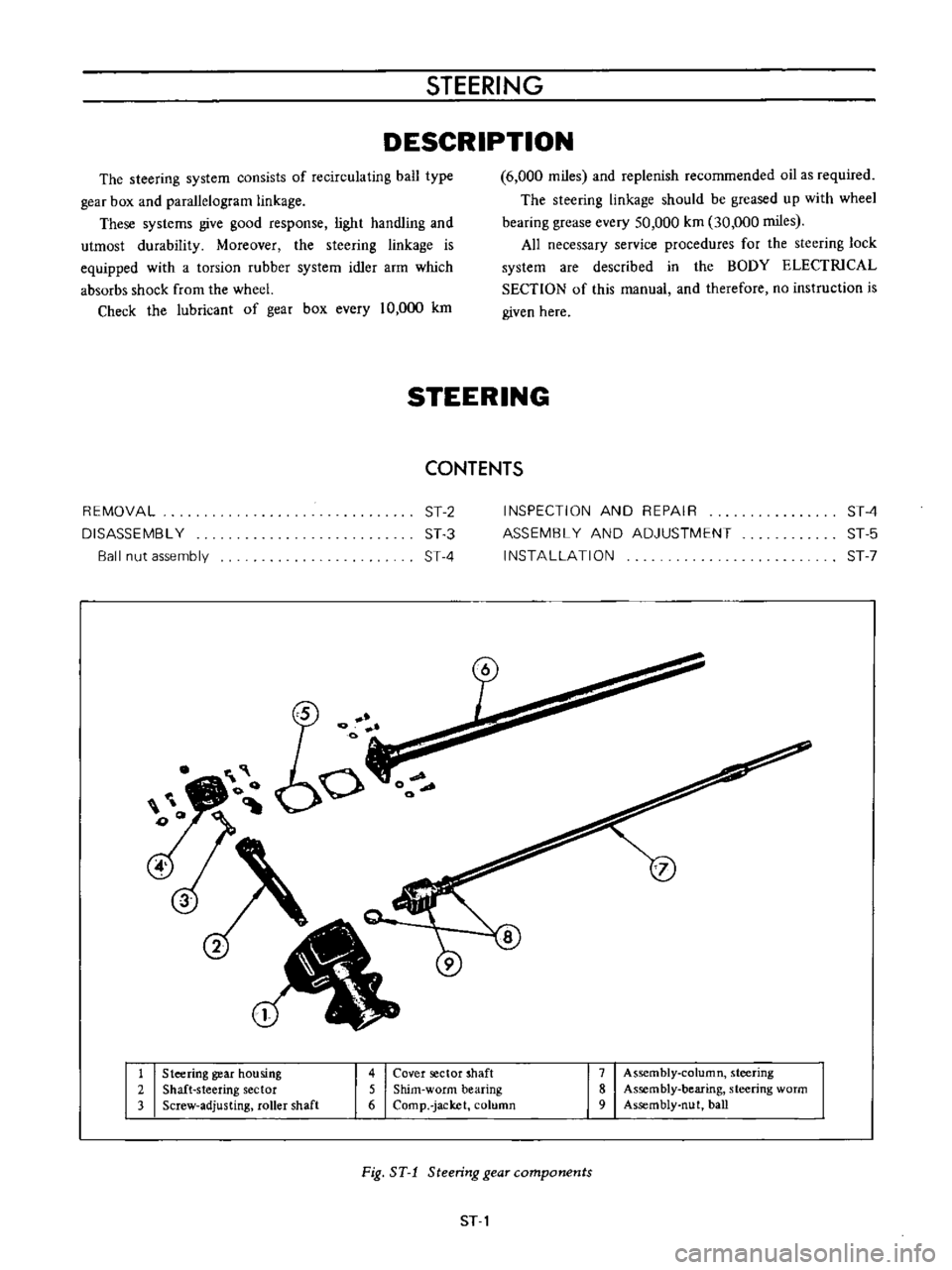
1
Steering
gear
housing
2
Shaft
steering
sector
3
Screw
adjusting
roller
shaft
4
Cover
sector
shaft
5
Shim
worm
bearing
6
Comp
jacket
column
7
Assembly
column
steering
8
Assembly
bearing
steering
worm
9
Assembly
nut
ball
Fig
ST
1
Steering
gear
components
ST
1
Page 162 of 513

Iii
I
o
t
I
I
CHASSIS
Fig
ST
2
Steering
wheel
REMOVAL
1
Remove
the
horn
ring
and
remove
the
steering
wheel
nut
and
pull
out
the
steering
wheel
by
the
use
of
a
Steer
ing
wheel
puller
ST27180000
3
Remove
the
turn
signal
and
lighting
switch
com
pletely
4
Remove
the
hand
lever
assembly
from
the
control
rod
assembly
by
unscrewing
the
fIxing
bolts
5
Remove
two
fIxing
bolts
used
to
secure
the
steering
column
to
the
instrument
panel
ST27180000
Fig
ST
3
Removing
steering
wheel
lock
nut
Note
The
horn
ring
can
be
easily
removed
by
two
bolts
2
Remove
the
steering
column
shell
Fig
ST
4
Removing
steering
column
upper
side
ST
2
Page 166 of 513
I
CHASSIS
4
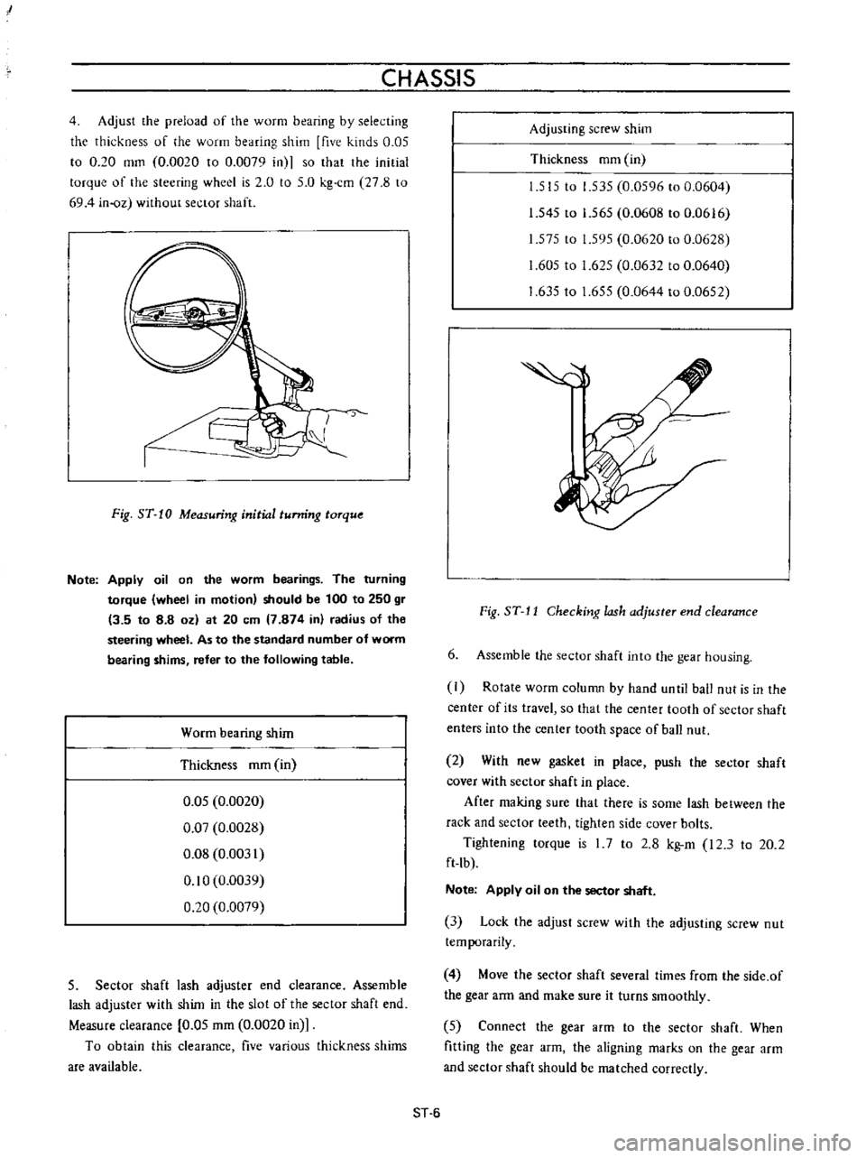
Adjust
the
preload
of
the
worm
bearing
by
selecting
the
thickness
of
he
worm
bearing
shim
five
kinds
0
05
to
0
20
mm
0
0020
to
0
0079
in
so
that
the
initial
torque
of
the
steering
wheel
is
2
0
to
5
0
kg
cm
27
8
to
694
in
oz
without
sector
shaft
J
Fig
ST
10
Measuring
initial
tunring
torque
Note
Apply
oil
on
the
worm
bearings
The
turning
torque
wheel
in
motion
should
be
100
to
250
gr
13
5
to
8
8
oz
at
20
em
7
874
in
radius
of
the
steering
wheel
As
to
the
standard
number
of
worm
bearing
shims
refer
to
the
following
table
Worm
bearing
shim
Thickness
mm
in
0
05
0
0020
0
07
0
0028
0
08
0
0031
0
10
0
0039
0
20
0
0079
5
Sector
shaft
lash
adjuster
end
clearance
Assemble
lash
adjuster
with
shim
in
the
slot
of
the
sector
shaft
end
Measure
clearance
0
05
mm
0
0020
in
To
obtain
this
clearance
five
various
thickness
shims
are
available
Adjusting
screw
shim
Thickness
mm
in
1
515
to
1
535
0
0596
to
0
0604
1
545
to
1
565
0
0608
to
0
0616
1
575
to
1
595
0
0620
to
0
0628
1
605
to
1
625
0
0632
to
0
0640
1
63510
1
655
0
0644
to
0
0652
Fig
ST
J
J
Checking
lash
adjuster
end
clearance
6
Assemble
the
sector
shaft
into
the
gear
housing
I
Rotate
worm
column
by
hand
unlil
ball
nut
is
in
the
center
of
its
travel
so
that
the
center
tooth
of
sector
shaft
enters
into
the
center
tooth
space
of
ball
nut
2
With
new
gasket
in
place
push
the
sector
shaft
cover
with
sector
shaft
in
place
After
making
sure
that
there
is
some
lash
between
the
rack
and
sector
teeth
tighten
side
cover
bolts
Tightening
torque
is
I
7
to
2
8
kg
m
I2
3
to
20
2
ft
lb
Note
Apply
oil
on
the
sector
shaft
3
Lock
the
adjust
screw
with
the
adjusting
screw
nut
temporarily
4
Move
the
sector
shaft
several
times
from
the
side
of
the
gear
arm
and
make
sure
it
turns
smoothly
5
Connect
the
gear
arm
to
the
sector
shaft
When
fitting
the
gear
arm
the
aligning
marks
on
the
gear
arm
and
sector
shaft
should
be
matched
correctly
ST
6
Page 167 of 513
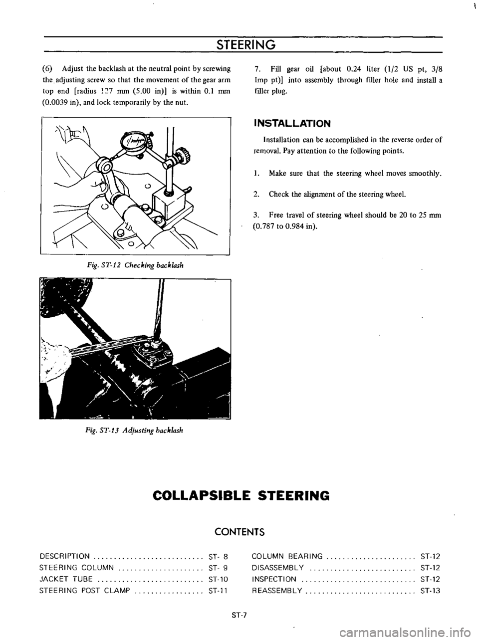
STEERING
6
Adjust
the
backlash
at
the
neutral
point
by
screwing
the
adjusting
screw
so
that
the
movement
of
the
gear
arm
top
end
radius
7
mm
5
00
in
is
within
0
1
mm
0
0039
in
and
lock
temporarily
by
the
nut
Fig
ST
12
Checking
backlash
Fig
ST
13
Adjusting
backlash
7
Fill
gear
oil
about
0
24
liter
I
2
US
pt
3
8
Imp
pt
into
assembly
through
f1ller
hole
and
install
a
mIer
plug
INSTALLATION
Installation
can
be
accomplished
in
the
reverse
order
of
removal
Pay
attention
to
the
following
points
I
Make
sure
that
the
steering
wheel
moves
smoothly
2
Check
the
alignment
of
the
steering
wheeL
3
Free
travel
of
steering
wheel
should
be
20
to
25
mm
0
787
to
0
984
in
COLLAPSIBLE
STEERING
CONTENTS
DESCRIPTION
STEERING
COLUMN
JACKET
TUBE
STEERING
POST
CLAMP
ST
8
ST
9
ST
10
ST
11
COLUMN
BEARING
DISASSEMBL
Y
INSPECTION
REASSEMBL
Y
ST
12
ST
12
ST
12
ST
13
ST
7
Page 168 of 513
CHASSIS
I
l
I
I
2
fa
r
o
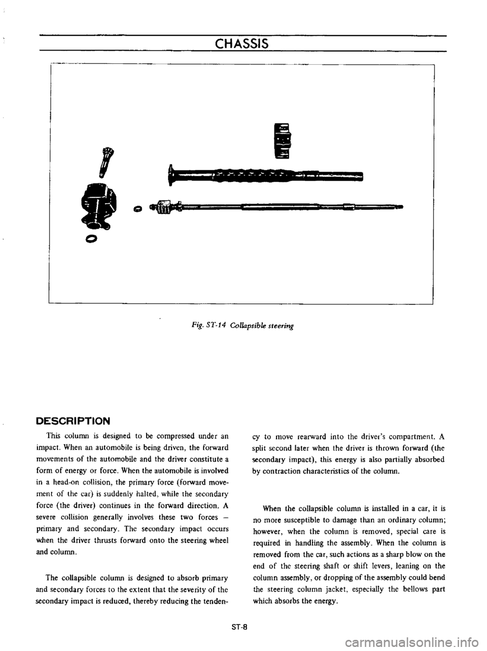
Fig
ST
14
Collapsible
steering
DESCRIPTION
This
column
is
designed
to
be
compressed
under
an
impact
When
an
automobile
is
being
driven
the
forward
movements
of
the
automobile
and
the
driver
constitute
a
form
of
energy
or
force
When
the
automobile
is
involved
in
a
head
on
collision
the
primary
force
forward
move
ment
of
the
car
is
suddenly
halted
while
the
secondary
force
the
driver
continues
in
the
forward
direction
A
severe
collision
generally
involves
these
two
forces
primary
and
secondary
The
secondary
impact
occurs
when
the
driver
thrusts
forward
onto
the
steering
wheel
and
column
The
collapsible
column
is
designed
to
absorb
primary
and
secondary
forces
to
the
extent
that
the
severity
of
the
secondary
impact
is
reduced
thereby
reducing
the
tenden
cy
to
move
rearward
into
the
driver
s
compartment
A
split
second
later
when
the
driver
is
thrown
forward
the
secondary
impact
this
energy
is
also
partially
absorbed
by
contraction
characteristics
of
the
column
When
the
collapsible
column
is
installed
in
a
car
it
is
no
more
susceptible
to
damage
than
an
ordinary
column
however
when
the
column
is
removed
special
care
is
required
in
handling
the
assembly
When
the
column
is
removed
from
the
car
such
actions
as
a
sharp
blow
on
the
end
of
the
steering
shaft
or
shift
levers
leaning
on
the
column
assembly
or
dropping
of
the
assembly
could
bend
the
steering
column
jacket
especially
the
bellows
part
which
absorbs
the
energy
ST
8