1973 DATSUN B110 oil type
[x] Cancel search: oil typePage 383 of 513
LUBRICATION
CIRCUIT
Oil
drawn
from
the
oil
pan
through
the
inlet
screen
and
tube
to
the
inlet
side
of
the
oil
pump
is
delivered
by
th
oil
pump
through
the
outlet
portion
of
the
oil
pump
and
the
oil
gallery
to
the
inlet
side
of
the
full
flow
oil
filter
and
to
the
main
oil
gallery
The
main
oil
gallery
supplies
oil
to
the
crankshaft
main
bearings
and
drilled
passages
in
the
crankshaft
and
thus
oil
is
fed
directly
from
the
main
bearings
to
the
connecting
rod
bearings
Oil
injected
from
jet
holes
on
connecting
rods
lubri
cates
the
cylinder
walls
and
pistion
pins
The
oil
distributed
from
the
main
gallery
enters
the
chain
teosioner
and
the
pad
is
held
against
the
chain
by
oil
pressure
and
spring
The
oil
also
lubricates
the
timing
chain
through
the
jet
hole
located
near
the
chain
Furthermore
lubricant
is
supplied
to
each
camshaft
bearing
through
each
crankshaft
main
bearing
and
finally
to
the
011
gallery
in
the
rocker
shaft
through
the
center
camshaft
bearing
The
rocker
arm
and
valve
are
lubricated
by
the
oil
through
the
oil
gallery
in
the
rockershaft
To
this
oil
gallery
lubricant
is
supplied
through
the
center
camshaft
bearing
as
shown
in
Figure
EL
I
OIL
PUMP
Description
The
oil
pump
assembly
is
installed
on
the
bottom
of
the
cylinder
block
and
driven
by
the
distributor
drive
shaft
assembly
The
oil
pump
is
of
a
rotor
type
The
oil
pressure
is
regulated
by
the
regulator
valve
camshaft
Removal
Engine
in
vehicle
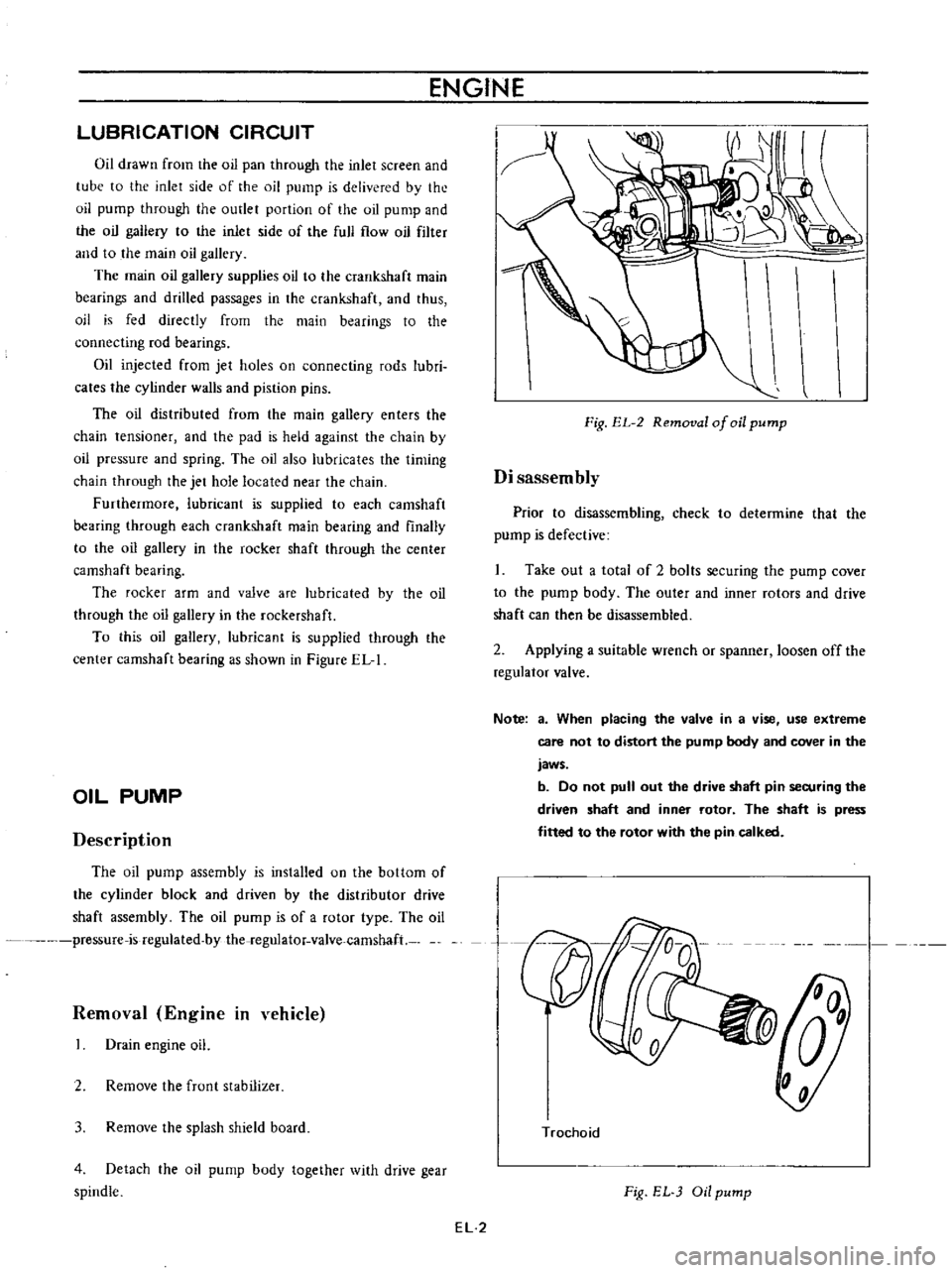
Drain
engine
oil
2
Remove
the
frunt
stabilizer
3
Remove
the
splash
shield
board
4
Detach
the
oil
pump
body
together
with
drive
gear
spindle
ENGINE
Fig
EL
2
Removal
of
oil
pump
Disassembly
Prior
to
disassembling
check
to
determine
that
the
pump
is
defective
Take
out
a
total
of
2
bolts
securing
the
pump
cover
to
the
pump
body
The
outer
and
inner
rotors
and
drive
shaft
can
then
be
disassembled
2
Applying
a
suitable
wrench
or
spanner
loosen
off
the
regulator
valve
Note
a
When
placing
the
valve
in
a
vise
use
extreme
care
not
to
distort
the
pump
body
and
cover
in
the
jaws
b
Do
not
pull
out
the
drive
shaft
pin
securing
the
driven
shaft
and
inner
rotor
The
shaft
is
press
fitted
to
the
rotor
with
the
pin
calked
n
Trochoid
Fig
EL
Oil
pump
EL
2
Page 384 of 513
ENGINE
LUBRICATION
SYSTEM
Inspection
and
repair
Clean
the
disassembled
parts
with
cleaning
solvent
and
inspect
for
defects
Inspect
the
drive
rotor
shaft
for
excessive
wear
and
scores
and
check
the
following
clearances
Side
clearance
between
Quter
and
inner
rotors
0
12
mm
0
0047
in
or
below
Tip
clearance
0
04
to
0
I2mm
0
0016
to
0
0047
in
Clearance
between
outer
rotor
and
body
0
15
to
0
21
rom
0
0059
to
0
0083
in
Adjusting
regulator
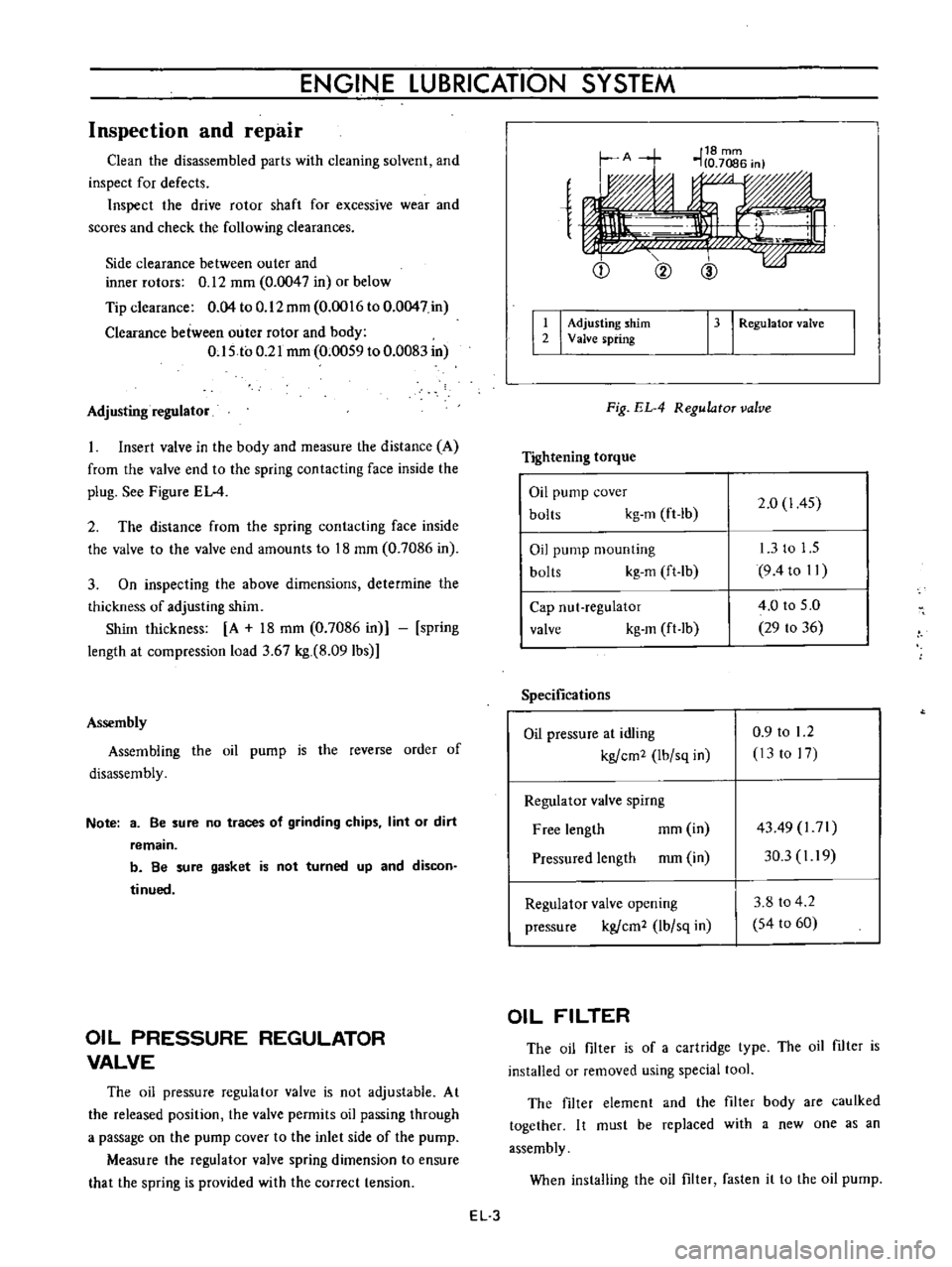
Insert
valve
in
the
body
and
measure
the
distance
A
from
the
valve
end
to
the
spring
contacting
face
inside
the
plug
See
Figure
EL
4
2
The
distance
from
the
spring
contacting
face
inside
the
valve
to
the
valve
end
amounts
to
18
mm
0
7086
in
3
On
inspecting
the
above
dimensions
determine
the
thickness
of
adjusting
shim
Shim
thickness
A
18
mm
0
7086
in
spring
length
at
compression
load
3
67
kg
8
091bs
Assembly
Assembling
the
oil
pump
is
the
reverse
order
of
disassembly
Note
3
Be
sure
no
traces
of
grinding
chips
lint
or
dirt
remain
b
Be
sure
gasket
is
not
turned
up
and
discon
tinued
OIL
PRESSURE
REGULATOR
VALVE
The
oil
pressure
regulator
valve
is
not
adjustable
At
the
released
position
the
valve
permits
oil
passing
through
a
passage
on
the
pump
cover
to
the
inlet
side
of
the
pump
Measure
the
regulator
valve
spring
dimension
to
ensure
that
the
spring
is
provided
with
the
correct
tension
e
Q
@
I
I
Adjusting
shim
2
Valve
spring
13
I
RegulatoT
valve
Fig
EL
4
RegulatoT
valve
Tightening
torque
Oil
pump
cover
bolts
kg
m
ft
lb
2
0
1
45
Oil
pump
mounting
bolts
kg
m
ft
lb
13
to
1
5
9
4to
II
Cap
nut
regulator
valve
kg
m
ft
lb
4
0
to
5
0
29
to
36
Specifications
Oil
pressure
at
idling
kgfcm2
Ibfsq
in
0
9
to
1
2
13
to
17
Regulator
valve
spirng
Free
length
mm
in
Pressured
length
mm
in
4349
l71
30
3
I
19
Regulator
valve
opening
pressure
kgfcm2
lbfsq
in
3
8
to
4
2
54
to
60
OIL
FILTER
The
oil
filter
is
of
a
cartridge
type
The
oil
filter
is
installed
or
removed
using
special
tool
The
filter
element
and
the
filter
body
are
caulked
together
I
t
must
be
replaced
with
a
new
one
as
an
assembly
When
installing
the
oil
filter
fasten
it
to
the
oil
pump
EL
3
Page 385 of 513
ENGINE
Note
Do
not
oyerlasten
the
filter
or
oil
leakage
may
occur
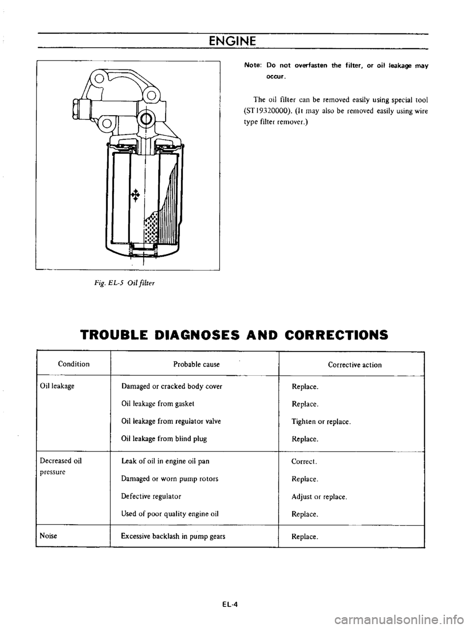
The
oil
filter
can
be
removed
easily
using
special
tool
STl9320000
It
may
also
be
removed
easily
using
wire
type
filter
remover
l
t
1
h
T
Fig
EL
5
Oil
filteT
TROUBLE
DIAGNOSES
AND
CORRECTIONS
Condition
Probable
cause
Corrective
action
Oil
leakage
Damaged
or
cracked
body
cover
Replace
Oil
leakage
from
gasket
Replace
Oil
leakage
from
regulator
valve
Tighten
or
replace
Oil
leakage
from
blind
plug
Replace
Decreased
oil
Leak
of
oil
in
engine
oil
pan
Correct
pressure
Damaged
or
worn
pump
rotors
Replace
Defective
regulator
Adjust
or
replace
Used
of
poor
quality
engine
oil
Replace
Noise
Excessive
backlash
in
pump
gears
Replace
EL
4
Page 399 of 513
ENGINE
INSPECTION
Check
the
upper
and
lower
bodies
for
cracks
2
Check
the
valve
assembly
for
wear
of
the
valve
and
valve
spring
Blow
the
valve
assembly
by
breath
to
examine
its
function
3
Check
the
diaphragm
for
small
holes
cracks
and
wear
4
Check
the
rocker
arm
for
wear
at
the
portion
in
contact
with
the
camshaft
5
Check
the
rocker
arm
pin
for
wear
since
a
worn
pin
may
cause
oil
leakage
6
Check
all
other
components
for
any
abnormalities
and
replace
with
new
parts
as
required
ASSEMBLY
Assembly
is
done
in
reverse
order
of
disassembly
For
reassembly
and
reinstallation
the
following
matters
should
be
noted
Use
new
gasket
2
Lubricate
the
rocker
arm
link
rocker
arm
pin
and
lever
pin
before
installation
3
To
test
the
function
position
the
fuel
pump
assem
bly
about
I
meter
3
3
ft
above
fuel
level
with
a
pipe
connecting
the
fuel
pump
and
the
fuel
strainer
and
operate
the
rocker
afm
by
hand
If
fuel
is
drawn
up
soon
after
the
rocker
arm
is
released
the
function
of
the
pump
is
satisfactory
CARBURETOR
CONTENTS
DESCRIPTION
STRUCTURE
AND
OPERATION
EF
8
EF
9
EF
10
EF
11
EF
12
EF
12
EF
12
EF
14
EF
14
EF
15
EF
15
EF
16
EF
16
Primary
system
Secondary
system
Anti
dieseling
solenoid
valve
Float
system
Electric
automatic
choke
ADJUSTMENT
Idling
adjustment
Fuel
level
adjustment
Fast
idle
adjustment
Vacuum
break
adjustment
Choke
un
loader
adjustment
DESCRIPTION
The
carburetors
are
of
a
downdraft
type
which
is
designed
and
built
to
increase
power
and
fuel
economy
as
Bi
metal
setting
Adjustment
of
interlock
opening
of
primary
and
secondary
throttle
valves
Dash
pot
adjustment
MAJOR
SERVICE
OPERATIONS
Removal
Disassembly
Cleaning
and
inspection
Assembly
and
installation
JETS
SERVICE
DATA
AND
SPECIFICATIONS
TROUBLE
DIAGNOSES
AND
CORRECTIONS
EF
17
EF
18
EF
18
EF
19
EF
19
EF
19
EF
21
EF
22
EF
22
EF
22
EF
22
well
as
to
reduce
the
emission
of
exhaust
gases
These
carburetors
present
several
distinct
features
of
importance
to
the
car
owners
A
summary
of
features
is
as
follows
EF
8
Page 436 of 513
ENGINE
r
Ignition
switJ
c
o
iArm
ture
j
i
i
VC2
P
tP2
d
I
I
I
PI
I
ll
Rl
L
I
I
lRJ
t
R
I
Field
e
I
I
I
I
Ps
I
1
I
I
n
I
coil
M
4
i
f
I
L
1
J
Alternator
Voltage
regulator
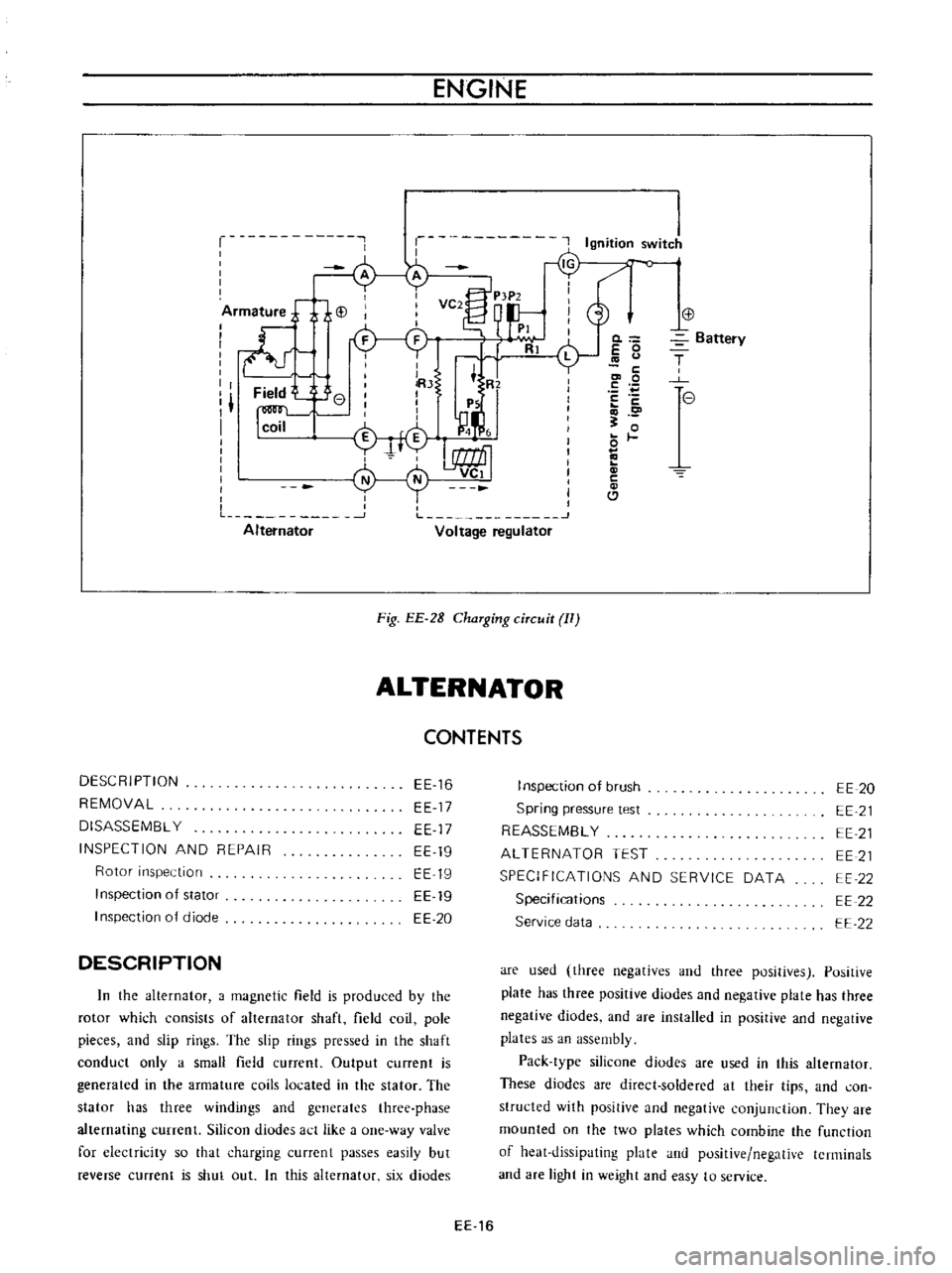
Fig
EE
2B
ChaTging
ciTcuit
II
ALTERNATOR
CONTENTS
DESCRIPTION
REMOVAL
DISASSEMBL
Y
INSPECTION
AND
REPAIR
Rotor
inspection
Inspection
of
stator
I
nspection
of
diode
EE
16
EE
17
EE
17
EE
19
EE
19
EE
19
EE
20
DESCRIPTION
In
the
alternator
a
magnetic
field
is
produced
by
the
rotor
which
consists
of
alternator
shaft
field
coil
pole
pieces
and
slip
rings
The
slip
rings
pressed
in
the
shaft
conduct
only
a
small
field
current
Output
current
is
generated
in
the
armature
coils
located
in
the
stator
The
stator
has
three
windings
and
generates
three
phase
alternating
currenl
Silicon
diudes
act
like
a
one
way
valve
for
electricity
so
that
charging
currcnt
passes
easily
but
reverse
current
is
shut
out
In
this
alternator
six
diodes
0
E
0
c
co
0
E
c
o
0
c
Cl
Battery
T
e
I
nspection
of
brush
Spring
pressure
test
REASSEMBL
Y
ALTERNATOR
TEST
SPECIFICATIONS
AND
SERVICE
DATA
Specifications
Service
data
EE
20
EE
21
EE
21
EE
21
EE
22
EE
22
EE
22
are
used
three
negatives
and
three
positives
Positive
plate
has
three
positive
diodes
and
negative
plate
has
three
negative
diodes
and
are
installed
in
positive
and
negative
plates
as
an
assembly
Pack
type
silicone
diodes
are
used
in
this
alternator
These
diodes
are
direct
soldered
at
their
tips
and
con
structed
with
positive
and
negative
conjunction
They
are
mounted
on
the
two
plates
which
combine
the
function
of
heat
dissipating
plate
and
positive
negative
terminals
and
are
light
in
weight
and
easy
to
service
EE
16
Page 442 of 513
ENGINE
terminal
to
IN
terminal
or
BAT
terminal
Connect
the
other
test
probe
to
ground
Make
sure
that
voltmeter
registers
battery
voltage
4
Start
the
engine
3
Turn
on
the
headlights
and
switch
to
main
beam
I
o
B
ttefY
E
A
J
0
il
I
5
Increase
engine
speed
gradually
until
it
is
approxi
mately
1
100
rpm
and
take
the
voltmeter
reading
6
If
the
measured
value
is
over
12
5
volts
the
alternator
is
in
good
condition
o
I
eE052
Voltmeter
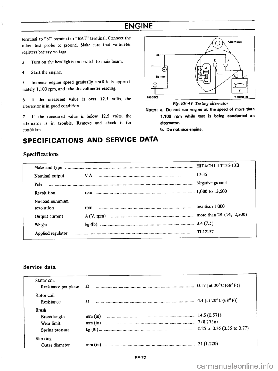
Fig
EE
49
Testing
altematoT
Notes
8
Do
not
run
engine
at
the
speed
of
more
than
1
100
rpm
while
test
is
being
conducted
on
alternator
b
Do
not
race
engine
7
If
the
measured
value
is
below
12
5
volts
the
alternator
is
in
trouble
Remove
and
check
it
for
condition
SPECIFICATIONS
AND
SERVICE
DATA
Specifications
Make
and
type
Nominal
output
Pole
Revolution
No
load
minimum
revolution
Output
current
Wei
t
Applied
regulator
Service
data
Stator
coil
Resistance
per
phase
Rotor
coil
Resistance
Brush
Brush
length
Wear
limit
Spring
pressure
Slip
ring
Outer
diameter
V
A
HITACHI
LTl35
13B
12
35
rpm
Negative
ground
1
000
to
13
500
rpm
A
V
rpm
kg
1b
less
than
1
000
more
than
28
14
2
500
3
4
7
5
TLl
Z
57
n
0
17
at
200C
680F
n
4
4
at
200e
680
F
mm
in
mm
in
kg
lb
14
5
0
571
7
0
2756
0
25
to
0
35
0
55
to
0
77
mm
in
31
1
220
EE
22
Page 456 of 513
ENGINE
Weight
pivot
diameter
mm
in
Weight
hole
diameter
mm
in
Clearance
between
pivot
and
hole
mmOn
5
0
028
0
9
9
1
0011
1
005
1
6
1
0002
5
1
018
0
1969
0
0007
o
0
0
005
to
0
046
0
0002
to
0
0018
IGNITION
COIL
CONTENTS
DESCRIPTION
EE
36
DESCRIPTION
The
Ignition
coil
is
of
an
oil
filled
type
The
ignition
coil
case
is
mted
with
oil
which
has
good
insulating
and
heat
radiating
characteristics
The
ignition
coil
has
a
greater
ratio
between
the
primary
and
secondary
windings
to
step
up
the
battery
voltage
to
the
high
voltage
to
cause
stronger
sparks
to
jump
the
spark
plug
gap
The
cap
is
made
of
alkyd
resin
which
offers
high
resistance
to
electric
arc
and
increased
insulation
The
resistor
in
the
ignition
coil
circuit
helps
produce
strong
sparks
from
starting
to
high
speed
full
power
operation
The
internal
resistor
limits
to
a
maximum
safe
flow
of
the
primary
current
through
the
coil
and
distributor
contact
points
Thus
it
protects
the
contact
points
during
slow
speed
operation
when
they
are
closed
for
long
intervals
The
ignition
coil
and
resistor
should
be
handled
as
a
matched
set
EE
36
SPECIFICATIONS
EE
37
@
@
@l
@
EE143
I
Primary
terminal
2
Secondary
terminal
3
Cap
4
Spring
5
Side
core
6
Primary
coil
7
Secondary
coil
8
insulator
oil
9
Center
core
10
Segment
tt
Case
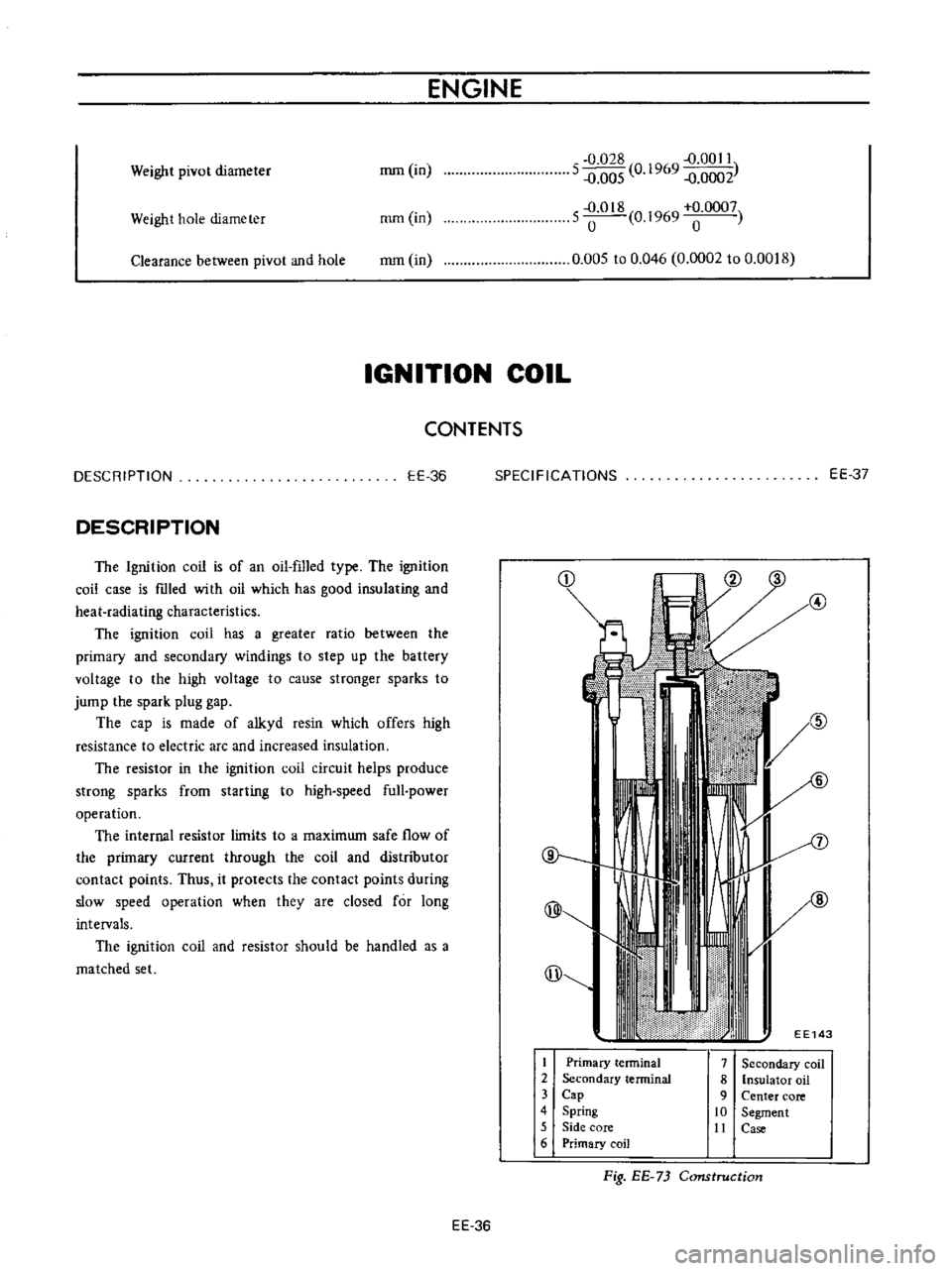
Fig
EE
73
Construction
Page 457 of 513
ENGINE
ElECTRICAL
SYSTEM
SPECIFICATIONS
Make
and
type
Primary
voltage
v
Spark
gap
mm
in
Primary
resistance
at
200C
680
F
n
Secondary
resistance
at
200C
680F
Kn
External
resistor
at
200C
680
F
n
Applied
resistor
HANSHIN
HITACHI
H5
15
2
C6R
601
12
12
more
than
7
more
than
7
0
28
0
28
1
17
to
I
43
l
l
7
to
I
43
11
2
to
16
8
11
2
to
16
8
l
3tol7
l
3tol7
RC
15
5560R
151O
SPARK
PLUG
CONTENTS
DESCRIPTION
INSPECTION
CLEANING
AND
REGAP
EE
37
EE
37
EE
38
DESCRIPTION
The
spark
plugs
are
of
the
resister
type
having
14
mm
0
551
in
threads
and
0
8
to
0
9
mm
0
031
to
0
Q35
in
gap
Note
All
spark
plugs
installed
on
an
engine
must
be
of
the
same
brand
and
number
of
heat
range
INSPECTION
1
Remove
spark
plug
wire
by
pulling
on
boot
not
on
wire
itself
2
Remove
spark
plugs
3
Check
electrodes
and
inner
and
outer
porcelains
of
plugs
noting
the
type
of
deposits
and
the
degree
of
electrode
erosion
Refer
to
Figure
EE
74
Normal
Brown
to
grayish
tan
deposits
and
slight
elec
trode
wear
indicate
correct
spark
plug
heat
range
SPECIFICATIONS
AND
SERVICE
DATA
TROUBLE
DIAGNOSES
AND
CORRECTIONS
EE
38
EE
39
Carbon
fouled
Dry
fluffy
carbon
deposits
on
the
insula
tor
and
electrode
were
mostly
caused
by
slow
speed
driving
in
city
weak
ignition
too
rich
fuel
mixture
dirty
air
cleaner
etc
H
is
advisable
to
replace
with
plugs
having
hotter
heat
range
Oil
fouled
Wet
black
deposits
show
excessive
oil
en
trance
into
combustion
chamber
through
worn
rings
and
pistons
or
excessive
clearance
between
valve
guides
and
stems
If
the
same
condition
remains
after
repair
use
a
hotter
plug
Overheating
White
or
light
gray
insulator
with
black
or
gray
brown
spots
and
bluish
burnt
electrodes
indicate
engine
overheating
Moreover
the
appearance
results
from
incorrect
ignition
timing
loose
spark
plugs
low
fuel
pump
pressure
wrong
selection
of
fuel
a
hotter
plug
etc
H
is
advisable
to
replace
with
plugs
having
colder
heat
range
EE
37