1973 DATSUN B110 oil type
[x] Cancel search: oil typePage 256 of 513

BODY
ElECTRICAL
When
the
ignition
switch
is
set
to
ON
the
ignition
wa
rning
circuit
is
closed
and
current
flows
flows
from
the
ignition
switch
to
the
warning
lamp
bulb
and
ground
through
the
regulator
When
the
engine
is
started
and
the
generator
comes
into
operation
the
generator
output
current
opposes
the
current
flowing
from
the
warning
lamp
in
effect
it
breaks
the
warning
circuit
ground
connection
and
the
lamp
goes
out
l
r
hffi
u
z
Ignition
switch
I
Q
6
I
0
c
M
1
E
8
ca
i
L
g
PI
lot
c
P
I
j
co
rt
0
relay
E
0
5
y
y
1
N
N
3
Alternator
Regulator
Fig
BE
41
Circuit
of
ignition
warning
system
HAND
BRAKE
WARNING
LAMP
This
lamp
functions
both
hand
brake
warning
larnp
and
BULB
SPECIFICATIONS
service
brake
line
pressure
differential
warning
lamp
When
a
difference
between
front
and
rear
brake
line
pressures
reaches
the
rated
range
13
to
17
kgfcm2
185
to
242
lb
sq
in
the
ground
circuit
for
the
warning
lamp
is
closed
and
the
warning
lamp
lights
IGNITION
SWITCH
WARNING
LAMP
L
E
WARNING
SWITCH
1
SERVICE
BRAKE
LINE
PRESSU
R
E
DIFFERENTIAL
WARNING
J
SWITCH
Fig
BE
42
Circuit
diagram
for
brake
warning
system
tern
Specifications
Square
type
meter
Round
type
meter
Meter
illumination
larnp
VoW
12
3
4
2
12
1
7
3
Turn
signal
pilot
lamp
VoW
12
3
4
2
12
1
7
2
Head
lamp
main
high
beam
VoW
12
3
4
I
12
17
1
pilot
lamp
Ignition
warning
lamp
VoW
123
4
I
12
17
1
Oil
pressure
warning
lamp
VoW
12
3
4
1
12
1
7
1
Hand
brake
warning
lamp
VoW
12
1
7
1
for
U
S
A
CANADA
Clock
illumination
lamp
VoW
123
4
I
12
17
2
Figure
encircled
in
parentheses
indicates
number
of
bulbs
used
BE
21
Page 302 of 513
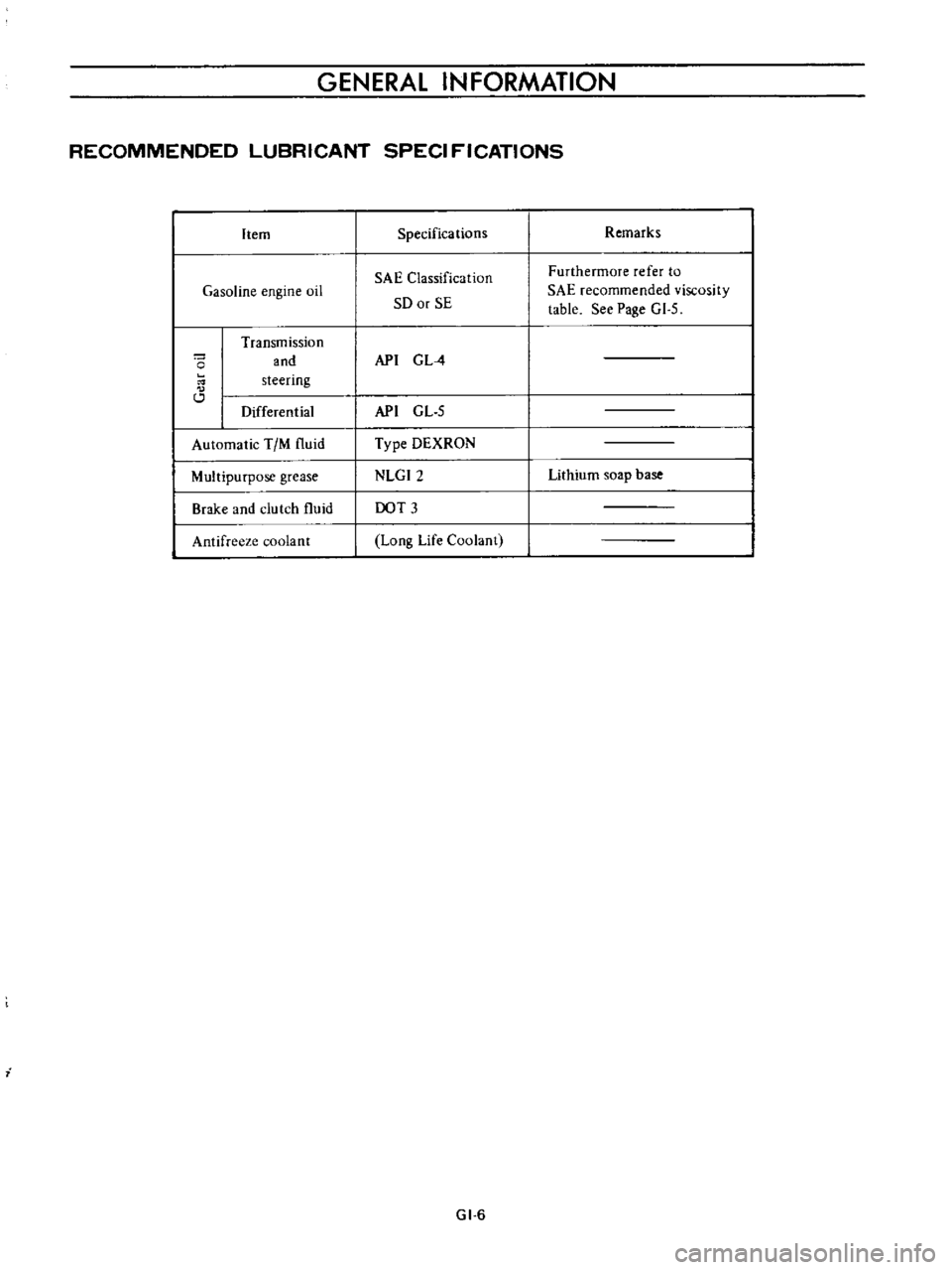
GENERAL
INFORMATION
RECOMMENDED
LUBRICANT
SPECI
FICATIONS
Item
Gasoline
engine
oil
o
Transmission
and
steering
Differential
Automatic
TIM
fluid
Multipurpose
grease
Brake
and
clutch
fluid
Antifreeze
coolant
i
Specifications
SAE
Classification
SO
or
SE
API
G
L
4
API
GL
5
Type
DEXRON
NLGI2
DOT
3
Long
Life
Coolant
GI
6
Remarks
Furthermore
refer
to
SAE
recommended
viscosity
table
See
Page
GI
5
Lithium
soap
base
Page 308 of 513
EMISSION
CONTROL
AND
TUNE
UP
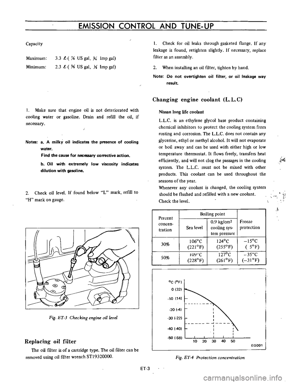
Capacity
Maximum
3
3
L
X
US
gal
y
Imp
gal
2
3
L
US
gal
f
Imp
gal
Minimum
Make
sure
that
engine
oil
is
not
deteriorated
with
cooling
water
or
gasoline
Drain
and
refill
the
oil
if
necessary
Notes
a
A
milky
oil
indicates
the
presence
of
cooling
water
Find
the
cause
for
necessary
corrective
action
b
Oil
with
extremely
low
viscosity
indicates
dilution
with
gasoline
2
Check
oil
level
If
found
below
L
mark
refill
to
H
mark
on
gauge
Fig
ET
3
Checking
engine
oil
level
Replacing
oil
filter
The
oil
ftIter
is
of
a
cartridge
type
The
oil
filter
can
be
removed
using
oil
ftIter
wrench
STl9320000
Check
for
oil
leaks
through
gasketed
flange
If
any
leakage
is
found
retighten
slightly
If
necessary
replace
filter
as
an
assembly
2
When
installing
an
oil
filter
tighten
by
hand
Note
Do
not
overtighten
oil
filter
or
oil
leakage
way
result
Changing
engine
coolant
L
L
C
Nissan
long
life
coolant
LLC
is
an
ethylene
glycol
base
product
containing
chemical
inhibitors
to
protect
the
cooling
system
from
rusting
and
corrosion
The
L
L
C
does
not
contain
any
glycerine
ethyl
or
methyl
alcohol
It
will
not
evaporate
or
boil
away
and
can
be
used
with
either
high
or
low
temperature
thermostat
It
flows
freely
transfers
heat
efficiently
and
will
not
clog
the
passages
in
the
cooling
system
The
LL
C
must
not
be
mixed
with
other
products
This
coolant
can
be
used
throughout
tlie
seasons
of
the
year
Whenever
any
coolant
is
changed
the
cooling
system
should
be
flushed
and
refilled
with
a
new
coolant
Check
the
level
J
Percent
Boiling
point
0
9
kgfcm2
Freeze
concen
tration
Sea
level
cooling
sys
protection
tern
pressure
30
1060
C
I
240C
15OC
221OF
255OF
5OF
50
IUY
C
1270C
35
C
2280
F
2610F
3IOF
DC
OF
0
321
10
14
20141
50
58
I
I
I
I
1
I
I
1
30
1
22
40
401
40
10
30
50
20
EGOOl
Fig
ET
4
Protection
concentration
ET
3
Page 342 of 513
ENGINE
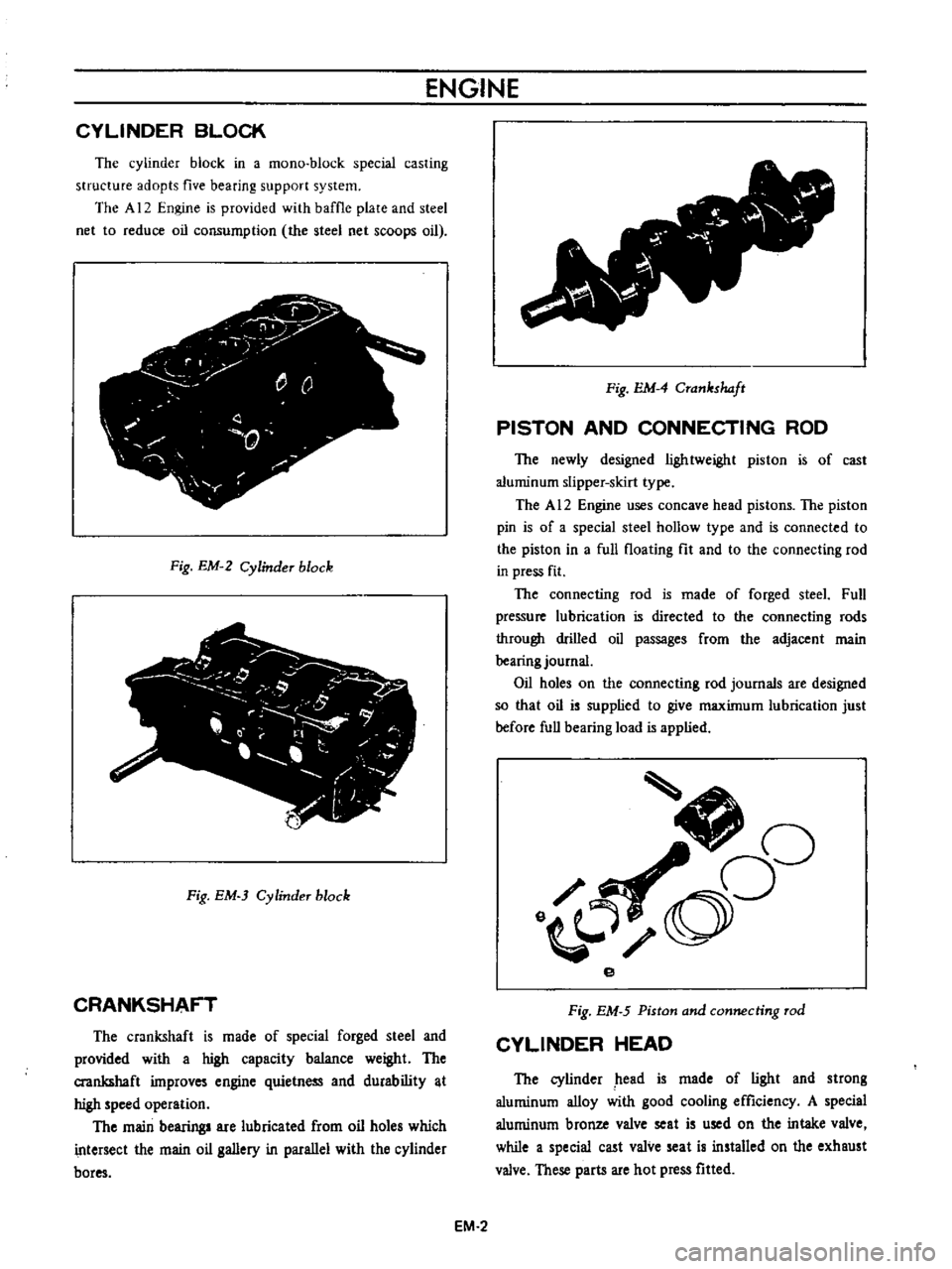
CYLINDER
BLOCK
The
cylinder
block
in
a
mono
block
special
casting
structure
adopts
five
bearing
support
system
The
A
12
Engine
is
provided
with
baffle
plate
and
steel
net
to
reduce
oil
consumption
the
steel
net
scoops
oil
j
y
r
0
Q
0
T
Fig
EM
2
Cylinder
block
Fig
EM
3
Cylinder
block
CRANKSHAFT
The
crankshaft
is
made
of
special
forged
steel
and
provided
with
a
high
capacity
balance
weight
The
crankshaft
improves
engine
quietness
and
durability
t
high
speed
operation
The
main
bearing
are
lubricated
from
oil
holes
which
intersect
the
main
oil
gallery
in
parallel
with
the
cylinder
bores
v
Fig
EM
4
Crankshaft
PISTON
AND
CONNECTING
ROD
The
newly
designed
lightweight
piston
is
of
cast
aluminum
slipper
skirt
type
The
A
12
Engine
uses
concave
head
pistons
The
piston
pin
is
of
a
special
steel
hollow
type
and
is
connected
to
the
piston
in
a
full
floating
fit
and
to
the
connecting
rod
in
press
fit
The
connecting
rod
is
made
of
forged
steeL
Full
pressure
lubrication
is
directed
to
the
connecting
rods
through
drilled
oil
passages
from
the
adjacent
main
bearing
journal
Oil
holes
on
the
connecting
rod
journals
are
designed
so
that
oil
is
supplied
to
give
maximum
lubrication
just
before
full
bearing
load
is
applied
J
oO
o
e
Fig
EM
5
Piston
and
connecting
rod
CYLINDER
HEAD
The
cylinder
head
is
made
of
light
and
strong
aluminum
alloy
with
good
cooling
efficiency
A
special
aluminum
bronze
valve
seat
is
used
on
the
intake
valve
while
a
special
cast
valve
seat
is
installed
on
the
exhaust
valve
These
parts
are
hot
press
fitted
EM
2
Page 343 of 513
ENGINE
MECHANICAL
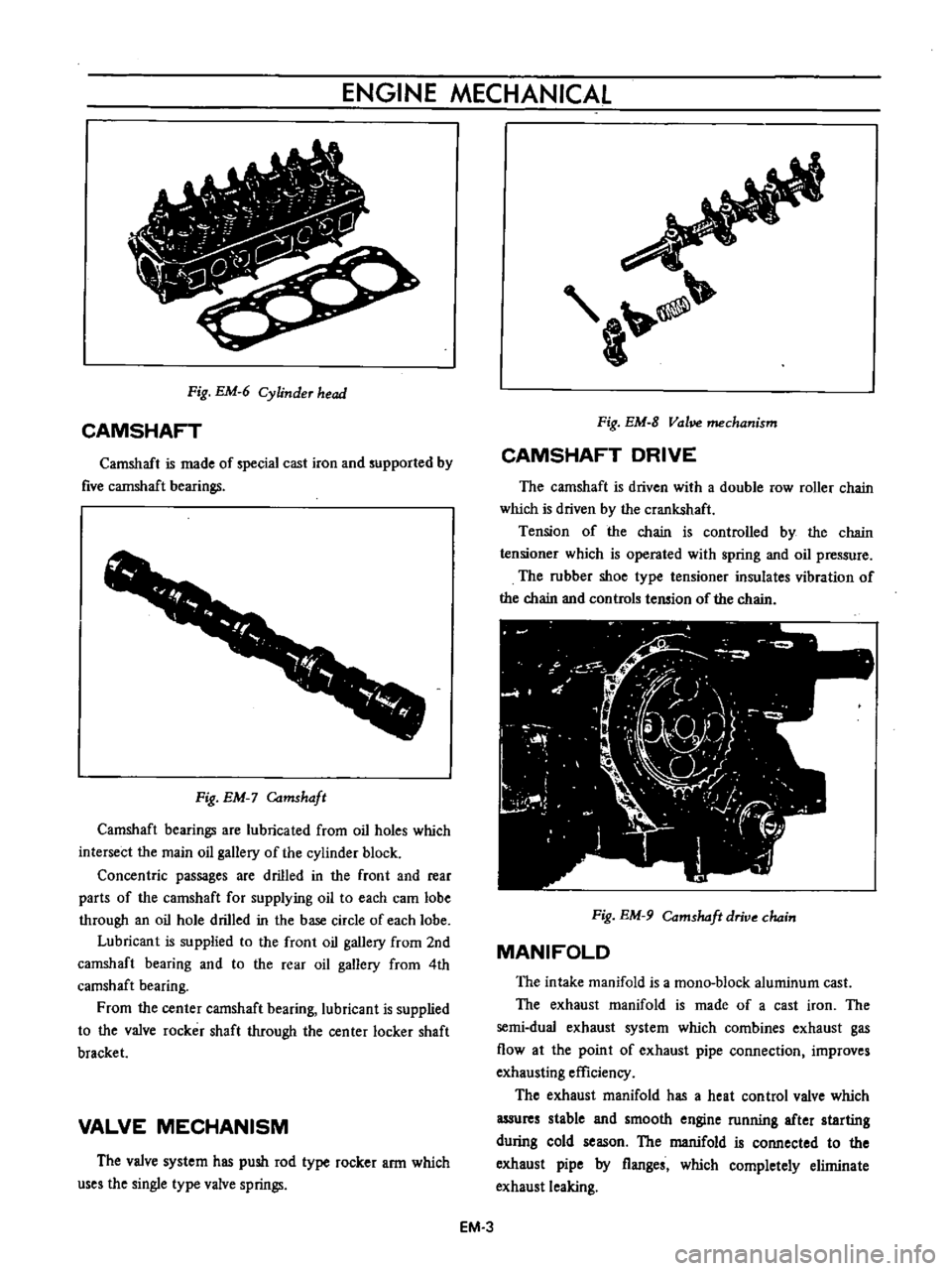
Fig
EM
6
Cylinder
head
CAMSHAFT
Camshaft
is
made
of
special
cast
iron
and
supported
by
five
cannshaft
bearings
1
1
f
r
f
r
I
Fig
EM
Camshaft
Camshaft
bearings
are
lubricated
from
oil
holes
which
intersect
the
main
oil
gallery
of
the
cylinder
block
Concentric
passages
are
drilled
in
the
front
and
rear
parts
of
the
camshaft
for
supplying
oil
to
each
cam
lobe
through
an
oil
hole
drilled
in
the
base
circle
of
each
lobe
Lubricant
is
supplied
to
the
front
oil
gallery
from
2nd
camshaft
bearing
and
to
the
rear
oil
gallery
from
4th
camshaft
bearing
From
the
center
camshaft
bearing
lubricant
is
supplied
to
the
valve
rocker
shaft
through
the
center
locker
shaft
bracket
VALVE
MECHANISM
The
valve
system
has
push
rod
type
rocker
arm
which
uses
the
single
type
valve
springs
a
Fig
EM
8
Vol
mechanism
CAMSHAFT
DRIVE
The
camshaft
is
driven
with
a
double
row
roller
chain
which
is
driven
by
the
crankshaft
Tension
of
the
chain
is
controlled
by
the
chain
tensioner
which
is
operated
with
spring
and
oil
pressure
The
rubber
shoe
type
tensioner
insulates
vibration
of
the
chain
and
controls
tension
of
the
chain
Fig
EM
9
Comshdft
drive
chain
MANIFOLD
The
intake
manifold
is
a
mono
block
aluminum
cast
The
exhaust
manifold
is
made
of
a
cast
iron
The
semi
dual
exhaust
system
which
combines
exhaust
gas
flow
at
the
point
of
exhaust
pipe
connection
improves
exhausting
efficiency
The
exhaust
manifold
has
a
heat
control
valve
which
assures
stable
and
smooth
engine
running
after
starting
during
cold
season
The
manifold
is
connected
to
the
exhaust
pipe
by
flanges
which
completely
eliminate
exhaust
leaking
EM
3
Page 366 of 513
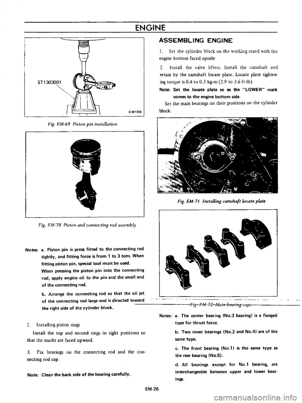
ENGINE
ST130300
1
EM156
Fig
EM
69
Piston
pin
installation
Fig
EM
70
Piston
and
connecting
rod
assembly
Notes
8
Piston
pin
is
press
fitted
to
the
connecting
rod
tightly
and
fitting
force
is
from
1
to
3
tons
When
fitting
piston
pin
special
tool
must
be
used
When
pressing
the
piston
pin
into
the
connecting
rod
apply
engine
oil
to
the
pin
and
the
small
end
of
the
connecting
rod
b
Arrange
the
connecting
rod
so
that
the
oil
jet
of
the
connecting
rod
large
end
is
directed
toward
the
right
side
of
the
cylinder
block
2
Installing
piston
rings
Install
the
top
and
second
fings
in
right
positions
so
that
the
marks
are
faced
upward
3
Fix
bearings
on
the
connecting
rod
and
the
con
necting
rod
cap
Note
Clean
the
back
side
of
the
bearing
carefully
ASSEMBLING
ENGINE
Set
the
cylinder
block
on
the
working
stand
with
the
engine
bottom
faced
upside
2
Install
the
valve
lifters
Install
the
camshaft
and
retain
by
the
camshaft
locate
plate
Locate
plate
tighten
ing
torque
is
0
4
to
0
5
kg
m
2
9
to
3
6
ft
lb
Note
Set
the
locate
plate
so
as
the
LOWER
mark
comes
to
the
engine
bottom
side
Set
the
main
bearings
on
their
positions
on
the
cylinder
block
Fig
EM
71
Installing
camshaft
ocate
plate
Fig
E1U
7
2
lvlajn
betlrj
lg
cap
Notes
a
The
center
bearing
No
3
bearing
is
a
flanged
type
for
thrust
force
b
Two
inner
bearings
No
2
and
No
4
are
of
the
same
type
c
The
front
bearing
No
1
is
the
same
type
a
the
rear
bearing
No
5
d
All
bearings
except
for
No
1
bearing
are
interchangeable
between
upper
and
lower
bear
ings
EM
26
Page 370 of 513
ENGINE
17
Install
the
oil
strainer
and
the
oil
pan
using
the
gasket
Apply
sealing
agent
on
hath
surfaces
of
the
gasket
especially
on
the
front
and
rear
portions
of
the
oil
pan
Oil
pan
tightening
torque
0
4
to
0
6
kg
m
I
9
to
4
3
ft
lbJ
I
R
I
nvcrt
the
engine
and
install
the
cylinder
head
assembly
and
gasket
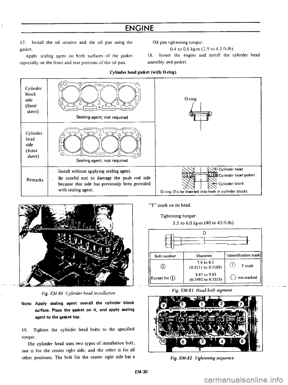
Cylinder
head
gasket
with
O
ring
Cylinder
block
side
Steel
sheet
D
QCO
0
0
i
O
1
nrr
11
I
Li
I
I
Vo
o
f
C
C
r
c
Sealing
agent
not
required
Cylinder
head
side
Joint
sheet
Remarks
Install
without
applying
sealing
agent
Be
careful
not
to
damage
the
push
rod
side
because
this
side
has
previously
been
provided
with
sealing
agent
Fig
EM
80
Cy
linder
head
installatjo
1
Note
Apply
sealing
agent
overall
the
cylinder
block
surface
Place
the
gasket
on
it
and
apply
sealing
agent
to
the
gasket
top
19
Tighten
the
cylinder
head
bolts
to
the
specified
torque
The
cylinder
head
uses
two
types
of
installation
bolt
one
is
for
the
center
right
side
and
the
other
is
for
all
other
positions
The
bolt
for
the
center
right
side
has
a
O
ring
j
I
Y
J
CYlinder
head
I
I
Cvlinderheadgasket
I
Cylinder
block
O
ring
To
be
inserted
into
hole
in
cylinder
block
T
mark
on
its
head
Tightening
torque
5
5
to
6
0
kg
m
40
to
43
ft
lb
fI
J
D
Bolt
number
Diameter
Identification
mark
CD
7
9
to
8
1
1
0
3111
to
0
3189
T
mark
Except
for
CD
8
87
to
9
03
o
not
marked
0
3492
to
0
3555
Fig
EM
8t
Head
bolt
segment
l
Fig
EM
82
Tightening
sequenc
EM
3D
Page 382 of 513
ENGINE
lUBRICATION
SYSTEM
LUBRICATION
SYSTEM
CONTENTS
DESCRIPTION
LUBRICATION
CIRCUIT
OIL
PUMP
Description
Removal
EL
1
EL
2
EL
2
EL
2
EL
2
Disassembly
I
nspection
and
repair
OIL
PRESSURE
REGULATOR
VALVE
OIL
FILTER
EL
2
EL
3
EL
3
EL
3
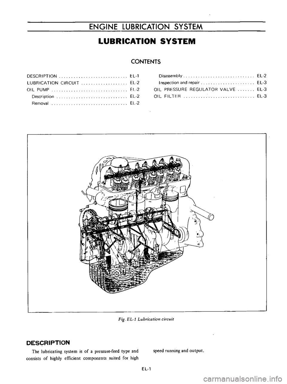
Fig
EL
l
Lubrication
circuit
DESCRIPTION
The
lubricating
system
is
of
a
pressure
feed
type
and
consists
of
highly
efficient
components
suited
for
high
speed
running
and
output
EL
1