1973 DATSUN B110 oil type
[x] Cancel search: oil typePage 88 of 513
CHASSIS
DESCRIPTION
The
front
suspension
is
of
a
strut
lype
The
shock
absurber
and
spindle
are
combined
to
a
single
unit
which
is
supported
by
the
coil
spring
at
the
upper
end
aod
by
the
transverse
link
at
the
lower
end
The
spindle
is
ins
tailed
on
the
bottom
of
the
strut
outer
casing
by
means
of
welding
A
ball
joint
is
attached
to
the
lower
part
of
the
spindle
The
ball
joint
and
the
transverse
link
lower
link
are
connected
and
they
are
fitted
to
the
suspension
member
through
a
rubber
bushing
The
shock
absorber
mechanism
is
built
in
the
strut
outer
casing
A
coil
spring
is
applied
between
the
upper
spring
seat
filled
to
the
upper
end
of
the
piston
rod
and
spring
seat
welded
to
the
outer
casing
These
components
assembled
to
a
single
unit
are
fitted
tu
the
chassis
frame
at
their
upper
part
through
the
thrust
bearing
Moreover
the
transverse
link
supports
the
overall
forward
and
backward
strut
movements
by
means
of
the
tension
rod
filled
to
the
chassis
frame
through
a
rubber
bushing
The
rubber
bushing
adopts
a
non
linear
shape
with
which
the
forward
and
rearward
rigidities
are
changed
The
torsion
bar
type
stabilizer
adopted
in
this
suspension
system
is
used
so
that
the
strut
maintains
connection
between
both
side
struts
Thus
this
suspension
mechanism
absorbs
shocks
toward
all
directions
into
the
chassis
effectively
and
efficiently
the
tension
rod
absorbs
forward
and
backward
shocks
the
strut
absorbs
vertical
shock
and
the
transverse
link
absorbs
shock
applied
toward
sideway
t
J
f
II
L
II
I
7
f
1
I
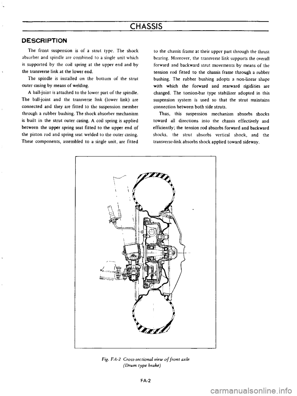
Fig
F
1
2
Cross
sectional
view
of
front
axle
Drum
type
brake
FA
2
Page 97 of 513
FRONT
AXLE
FRONT
SUSPENSION
t
t
Fig
FA
26
Returning
wheel
bearing
lock
nut
4
Turn
the
wheel
hub
a
few
turns
both
clockwise
and
counterclockwise
again
to
allow
the
bearing
breaking
in
measure
bearing
rotation
starting
torque
apply
a
cotter
pin
to
secure
the
nut
if
the
measured
starting
torque
is
within
the
rated
value
and
install
the
hub
cap
hub
cap
Wheel
bearing
rotation
starting
torque
9
0
kg
cm
7
8
in
1b
4
0
kg
cm
3
4
7
in
1b
At
the
hub
bolt
1
57
kg
3
461b
New
bearing
0
7
kg
1
54lb
Used
bearing
No
slackness
should
exist
toward
the
axis
direction
New
bearing
Used
bearing
J
o
i
@
j
Be
sure
to
remove
the
brake
pad
Disc
type
brake
Correctly
measure
starting
force
toward
tangential
direction
against
the
hub
bolt
Fig
FA
27
Measuring
wheel
bearing
ro
ation
starting
torque
STRUT
ASSEMBLY
The
strut
assembly
consisting
of
a
strut
outer
casing
with
spindle
forms
a
cylinder
between
the
piston
rod
guide
and
bottom
valve
The
inner
components
are
precisely
assembled
and
no
dirt
and
foreign
matter
intrusions
are
permitted
The
components
such
as
piston
rod
piston
rod
guide
cylinder
and
bottom
valve
are
handled
together
as
an
assembly
When
replacing
them
be
sure
to
replace
the
inner
components
as
an
assembly
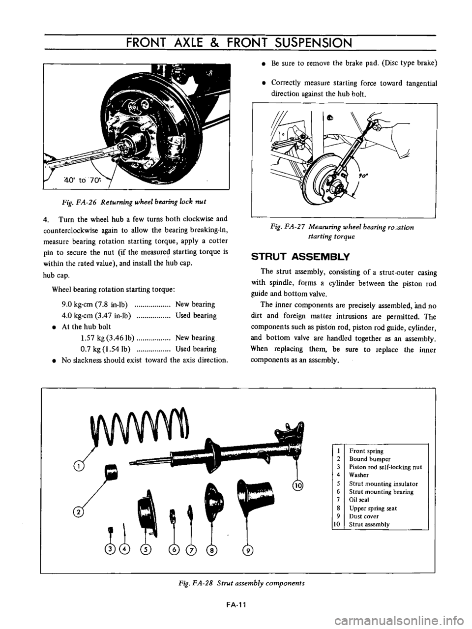
1
2
3
4
5
6
7
8
9
10
Front
spring
Bound
bumper
Piston
rod
self
locking
nut
Washer
Strut
mounting
insulator
Strut
mounting
bearing
Oil
seal
Upper
spring
seat
Dust
cover
Strut
assembly
Fig
FA
28
Strut
assembly
components
FA
l1
Page 103 of 513
FRONT
AXLE
FRONT
SUSPENSION
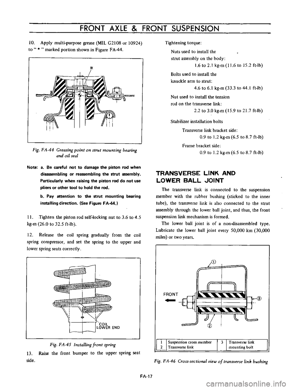
10
Apply
multi
purpose
grease
MIL
G2108
or
10924
to
marked
portion
shown
in
Figure
FA
44
Fig
FA
44
Greasing
point
on
strut
mounting
bearing
and
oil
seal
Note
a
Be
careful
not
to
damage
the
piston
rod
when
disassembling
or
reassembling
the
strut
assembly
Particularly
when
raising
the
piston
rod
do
not
use
pliers
or
other
tool
to
hold
the
rod
b
Pay
attention
to
the
strut
mounting
bearing
installing
direction
See
Figure
FA
44
1
L
Tighten
the
piston
rod
self
locking
nut
to
3
6
to
4
5
kg
m
26
0
to
32
5
ft
1b
12
Release
the
coil
spring
gradually
from
lhe
coil
spring
compressor
and
set
the
spring
to
the
upper
and
lower
spring
seats
correctly
f
I
I
COIL
l
J
LOWER
EN
D
Fig
FA
45
Installing
front
spring
13
Raise
the
front
bumper
to
the
upper
spring
seat
side
Tightening
torque
Nuts
used
to
install
the
strut
assembly
on
the
body
1
6
to
2
1
kg
m
11
6
to
15
2
ft
lb
Bolts
used
to
install
the
knuckle
arm
to
strut
4
6
to
6
1
kg
m
33
3
to
44
I
ft
lb
Nut
used
to
install
the
tension
rod
on
the
transverse
link
2
2
to
3
0
kg
m
15
9
to
21
7
ft
Ib
Stabilizer
inst
llation
bolts
Transverse
link
bracket
side
0
9
to
1
2
kg
m
6
5
to
8
7
ft
lb
Frame
bracket
side
0
9
to
1
2
kg
m
6
5
to
8
7
ft
lb
TRANSVERSE
LINK
AND
LOWER
BALL
JOINT
The
transverse
link
is
connected
to
the
suspension
member
with
the
rubher
bushing
sticked
to
the
inner
tube
the
transverse
link
is
also
connected
to
the
strut
assembly
through
the
lower
ball
joint
and
thus
the
front
suspension
link
mechanism
is
formed
The
lower
ball
joint
is
of
a
non
lisassembled
type
Lubricate
the
lower
ball
joint
every
50
000
km
30
000
miles
or
two
years
JD
y
I
II
I
II
F
T
ill
3
YJ
t
tjli
t
11
I
Suspension
cross
member
I
3
I
Transverse
link
2
Transverse
link
mounting
bolt
Fig
FA
46
Cross
sectional
view
of
transverse
link
bushing
FA
17
Page 116 of 513
REAR
AXLE
REAR
SUSPENSION
REAR
AXLE
CONTENTS
DESCRIPTION
REAR
AXLE
SHAFTS
Removal
RA
1
RA
l
RA
l
8
Inspection
Assembly
RA
3
RA
3
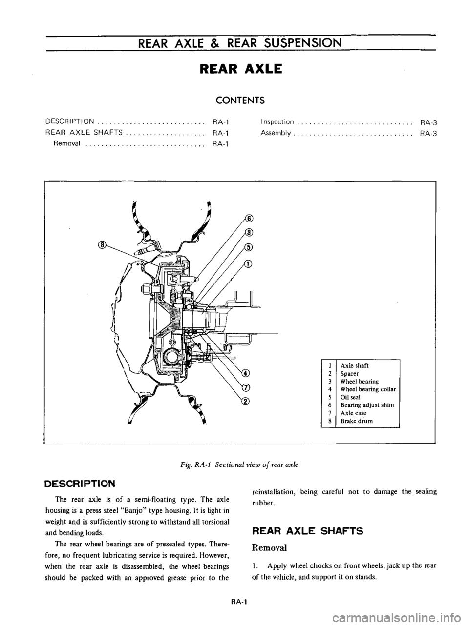
1
Axle
shaft
2
Spacer
3
Wheel
bearing
4
Wheel
bearing
collar
5
Oil
seal
6
Bearing
adjust
shim
7
Axle
case
8
Brake
drum
DESCRIPTION
Fig
RA
l
Sectional
view
of
rear
axle
The
rear
axle
is
of
a
semi
floating
type
The
axle
housing
is
a
press
steel
Banjo
type
housing
It
is
light
in
weight
and
is
sufficiently
strong
to
withstand
all
torsional
and
bending
loads
The
rear
wheel
bearings
are
of
presea1ed
types
There
fore
no
frequent
lubricating
service
is
required
However
when
the
rear
axle
is
disassembled
the
wheel
bearings
should
be
packed
with
an
approved
grease
prior
io
the
reinstallation
being
careful
not
to
damage
the
sealing
rubber
REAR
AXLE
SHAFTS
Removal
Apply
wheel
chocks
on
front
wheels
jack
up
the
rear
of
the
vehicle
and
support
it
on
stands
RA
l
Page 127 of 513
BRAKE
TANDEM
MASTER
CYLINDER
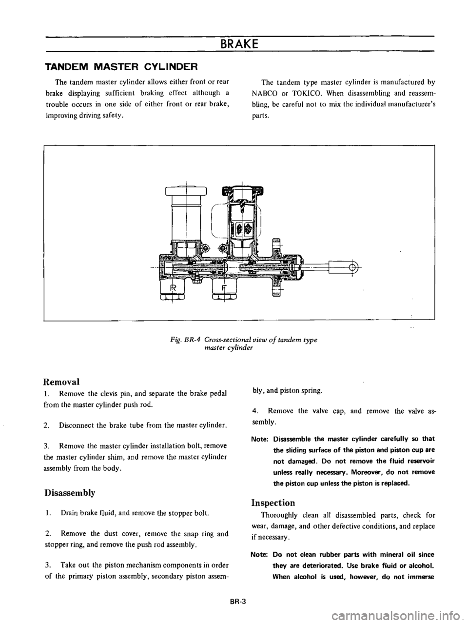
The
tandem
master
cylinder
allows
either
front
or
rear
brake
displaying
sufficient
braking
effect
although
a
trouble
occurs
in
one
side
of
either
front
or
rear
brake
improving
driving
safety
The
tandem
type
master
cylinder
is
manufactured
by
NABCO
or
TOKlCO
When
disassembling
and
reassem
bling
be
careful
not
to
mix
the
individual
manufacturer
s
parts
t
I
Fig
BR
4
Cross
sectional
view
of
tandem
type
master
cylinder
Removal
L
Remove
the
clevis
pin
and
separale
the
brake
pedal
from
the
master
cylinder
push
rod
2
Disconnect
the
brake
tube
from
the
master
cylinder
3
Remove
the
master
cylinder
installation
bolt
remove
the
master
cylinder
shim
and
remove
the
master
cylinder
assembly
from
the
body
Disassembly
L
Drain
brake
fluid
and
remove
the
stopper
bolt
2
Remove
the
dust
cover
remove
the
snap
ring
and
stopper
ring
and
remove
the
push
rod
assembly
3
Take
out
the
piston
mechanism
components
in
order
of
the
primary
piston
assembly
secondary
piston
assem
bly
and
piston
spring
4
Remove
the
valve
cap
and
remove
the
valve
as
sembly
Note
Disassemble
the
master
cylinder
carefully
so
that
the
sliding
surface
of
the
piston
and
piston
cup
are
not
damaged
Do
not
remove
the
fluid
reservoir
unless
really
necessary
Moreover
do
not
remove
the
piston
cup
unless
the
piston
is
replaced
Inspection
Thoroughly
clean
all
disassembled
parts
check
for
wear
damage
and
other
defective
conditions
and
replace
if
necessary
Note
Do
not
clean
rubber
parts
with
mineral
oil
since
they
are
deteriorated
Use
brake
fluid
or
alcohol
When
aloohol
is
used
however
do
not
immerse
BR
3
Page 161 of 513
STEERING
DESCRIPTION
The
steering
system
consists
of
recirculating
ball
type
gear
box
and
parallelogram
linkage
These
systems
give
good
response
light
handling
and
utmost
durability
Moreover
the
steering
linkage
is
equipped
with
a
torsion
rubber
system
idler
arm
which
absorbs
shock
from
the
wheel
Check
the
lubricant
of
gear
box
every
10
000
km
6
000
miles
and
replenish
recommended
oil
as
required
The
steering
linkage
should
be
greased
up
with
wheel
bearing
grease
every
50
000
km
30
000
miles
All
necessary
service
procedures
for
the
steering
lock
system
are
described
in
the
BODY
ELECTRICAL
SECTION
of
this
manual
and
therefore
no
instruction
is
given
here
STEERING
CONTENTS
REMOVAL
DISASSEMBL
Y
Ball
nut
assembly
ST
2
ST
3
ST
4
INSPECTION
AND
REPAIR
ASSEMBL
Y
AND
ADJUSTMENT
INSTALLATION
ST
4
ST
5
ST
7
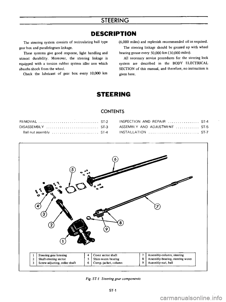
1
Steering
gear
housing
2
Shaft
steering
sector
3
Screw
adjusting
roller
shaft
4
Cover
sector
shaft
5
Shim
worm
bearing
6
Comp
jacket
column
7
Assembly
column
steering
8
Assembly
bearing
steering
worm
9
Assembly
nut
ball
Fig
ST
1
Steering
gear
components
ST
1
Page 177 of 513
STEERING
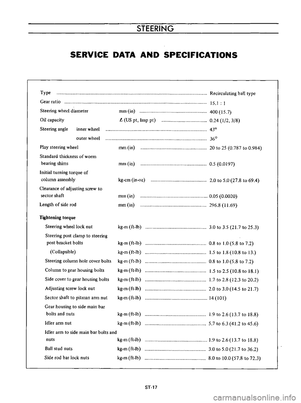
SERVICE
DATA
AND
SPECIFICATIONS
Type
Gear
ratio
Steering
wheel
diameter
Oil
capacity
Steering
angle
inner
wheel
outer
wheel
Play
steering
wheel
Standard
thickness
of
worrn
bearing
shims
Initial
turning
torque
of
column
assembly
Clearance
of
adjusting
screw
to
sector
shaft
Length
of
side
rod
Tightening
torque
Steering
wheel
lock
nut
Steering
post
clamp
to
steering
post
bracket
bolls
Collapsible
Steering
column
hole
cover
bolts
Column
to
gear
housing
bolts
Side
cover
to
gear
housing
bolts
Adjusting
screw
lock
nut
Sector
shaft
to
pitman
arm
nut
Gear
housing
to
side
main
bar
bolts
and
nuts
Idler
arm
nut
Recirculating
ball
type
mm
in
L
US
pt
Imp
pt
15
I
I
400
157
0
24
I
2
3
8
430
360
mm
in
20
to
25
0
787
to
0
984
mm
in
0
5
0
0197
kg
em
in
oz
2
0
to
5
0
27
8
to
69
4
mrn
in
mm
in
0
05
0
0020
296
8
11
69
kg
m
ft
lb
3
0
to
3
5
217
to
25
3
kg
m
ft
lb
kg
m
ft
Ib
kg
m
ft
lb
kg
m
ft
lb
kg
m
ft
lb
kg
m
ft
lb
kg
m
ft
lb
0
8
to
1
0
5
8
to
7
2
1
5
to
1
8
10
8
to
13
0
8
to
1
0
5
8
to
7
2
1
5
to
2
5
10
8
to
18
1
I
7
to
2
8
12
3
to
20
2
2
0
to
3
0
14
5
to
21
7
14
101
kg
m
ft
lb
kg
m
ft
lb
1
9
to
2
6
13
7
to
18
8
57
to
6
3
41
2
to
45
6
Idler
arm
to
side
main
bar
bolts
and
nuts
kg
m
ft
Ib
Ball
stud
nuts
kg
m
ft
lb
Side
rod
bar
lock
nuts
kg
m
ft
lb
1
9
to
2
6
13
7
to
18
8
3
0
to
5
0
21
7
to
36
2
8
0
to
10
0
57
8
to
72
3
ST
17
Page 228 of 513
@
c
@
CD
w
1
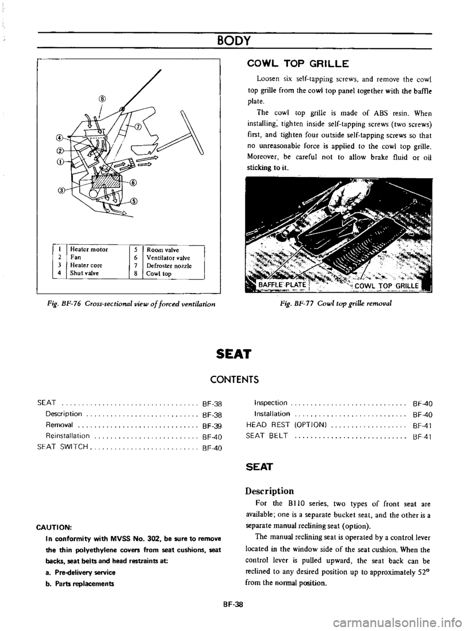
Heater
motor
2
Fan
3
Heater
core
4
Shut
valve
5
Room
valve
6
Ventilator
valve
7
Defroster
nozzle
8
Cowl
top
Fig
BF
76
Cross
sectional
view
of
forced
ventilation
BODY
COWL
TOP
GRILLE
Loosen
six
self
tapping
screws
and
remove
the
cowl
top
grille
from
the
cowl
top
panel
together
with
the
baffle
plate
The
cowl
top
grille
is
made
of
ABS
resin
When
installing
tighten
inside
self
tapping
screws
two
screws
first
and
lighten
four
outside
self
tapping
screws
so
that
no
unreasonable
force
is
applied
to
the
cowl
top
grille
Moreover
be
careful
not
to
allow
brake
fluid
or
oil
sticking
to
it
Fig
BF
77
Cowl
top
grille
removal
SEAT
CONTENTS
SEAT
Description
Removal
Reinstallation
SEAT
SWI
TCH
BF
38
BF
38
BF
39
BF
40
BF
40
CAUTION
I
n
conformity
with
MVSS
No
302
be
sure
to
remove
the
thin
polyethylene
covers
from
seat
cushions
seat
backs
seat
belts
and
head
restraints
at
a
Pi
Helivery
service
b
Parts
replacements
Inspection
Installation
HEAD
REST
OPTIONI
SEAT
BELT
BF
40
BF
40
BF
41
BF
41
SEAT
Description
For
the
BHO
series
two
types
of
front
seat
are
available
one
is
a
separate
bucket
seat
and
the
other
is
a
separate
manual
reclining
seat
option
The
manual
reclining
seat
is
operated
by
a
control
lever
located
in
the
window
side
of
the
seat
cushion
When
the
control
lever
is
pulled
upward
the
seat
back
can
be
reclined
to
any
desired
position
up
to
approximately
520
from
the
normal
position
BF
38