1973 DATSUN B110 tow
[x] Cancel search: towPage 170 of 513

CHASSIS
The
construction
of
the
steering
column
is
as
such
that
the
lower
shaft
is
fitted
into
the
upper
tube
when
a
compressing
force
is
applied
to
the
lower
shaft
r
I
1
V
f
7
Steering
torque
is
transmitted
by
the
lower
shaft
and
upper
tube
The
lower
shaft
adopts
a
special
shape
a
circle
with
two
straight
cut
edges
and
the
upper
tube
interior
is
tightly
fitted
against
the
lower
shaft
exterior
toward
the
entire
area
In
addition
four
plastic
pins
completely
eliminate
gap
between
the
lower
shaft
exterior
and
upper
tube
interior
I
I
Jacket
lube
2
Shaft
stopper
I
3
I
Column
coUar
4
Column
shaft
When
a
compressing
force
is
applied
the
above
described
plastic
pins
are
cut
and
the
lower
shaft
is
fitted
into
the
upper
tube
When
the
lower
shaft
is
once
fitted
into
the
upper
tube
the
shaft
end
spreads
and
the
lower
shaft
cannot
be
withdrawn
unless
an
extremely
high
load
is
applied
Fig
ST
1
7
Shaft
stopper
Moreover
for
rearward
column
shaft
projection
the
collar
for
steering
lock
installed
on
the
shaft
runs
against
stoppers
in
three
places
on
the
jacket
tube
which
allows
the
column
shaft
fitting
and
thus
reaIWard
projection
is
prevented
Note
In
no
event
should
an
impact
or
large
power
be
applied
to
the
shaft
with
a
hammer
or
other
matter
during
disassembly
or
reassembly
The
column
shaft
lower
end
and
upper
end
are
supported
respectively
by
two
worm
hearings
and
a
colwnn
bushing
JACKET
TUBE
w
1
U
II
I
II
I
r
liJl
I
I
D
I
1
1
Mesh
tube
I
2
Jacket
tube
Fig
ST
18
Jacket
tube
ST
10
Page 172 of 513
CHASSIS
The
sliding
block
is
secured
on
the
steering
post
bracket
with
bolts
upper
half
of
the
steering
column
is
supported
on
the
bracket
and
thus
the
steering
post
clamp
is
installed
on
the
body
When
a
large
impact
is
applied
from
the
driver
side
the
plastic
pins
are
cut
off
and
leaving
the
sliding
block
in
the
steering
post
bracket
side
the
clamp
proper
is
disengaged
downward
together
with
the
jacket
tube
For
any
force
applied
from
front
direction
of
the
vehicle
the
steering
post
clamp
sliding
block
does
not
move
rearward
This
construction
is
called
One
way
slide
system
and
with
this
construction
projection
of
the
column
shaft
toward
the
driver
is
prevented
completely
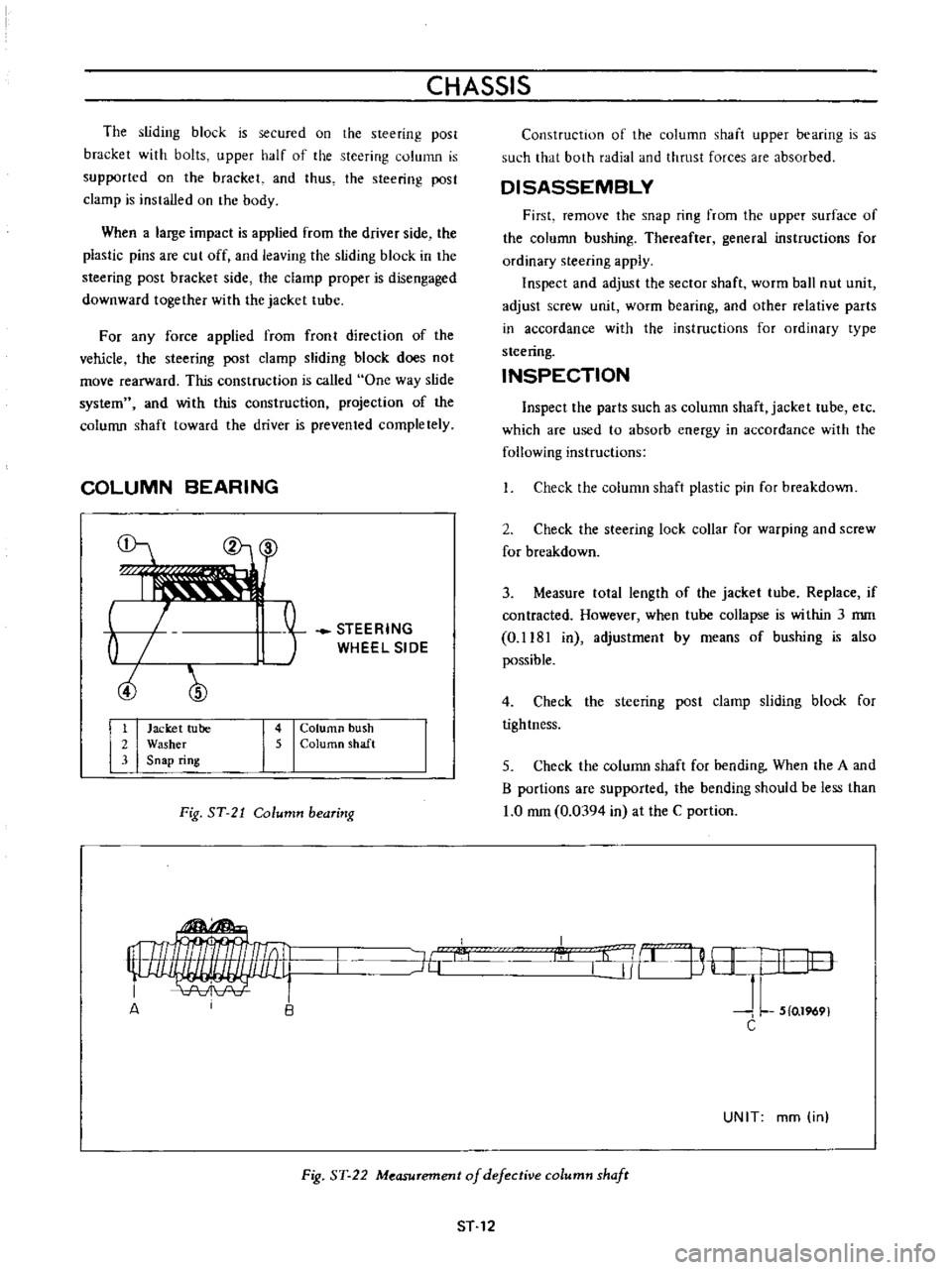
COLUMN
BEARING
b
ciJ
STEERING
WHEEL
SIDE
1
Jacket
tube
2
Washer
3
Snap
ring
4
Column
bush
5
ColurtlO
shaft
Fig
ST
21
Column
bearing
Construction
of
the
column
shaft
upper
bearing
is
as
such
that
both
radial
and
thrust
forces
are
absorbed
DISASSEMBLY
First
remove
the
snap
ring
from
the
upper
surface
of
the
column
bushing
Thereafter
general
instructions
for
ordinary
steering
apply
Inspect
and
adjust
the
sector
shaft
worm
ball
nut
unit
adjust
screw
unit
worm
bearing
and
other
relative
parts
in
accordance
with
the
instructions
for
ordinary
type
steering
INSPECTION
Inspect
the
parts
such
as
column
shaft
jacket
tube
etc
which
are
used
to
absorb
energy
in
accordance
with
the
following
instructions
Check
the
column
shaft
plastic
pin
for
breakdown
2
Check
the
steering
lock
collar
for
warping
and
screw
for
breakdown
3
Measure
tolal
length
of
the
jacket
tube
Replace
if
contracted
However
when
tube
collapse
is
within
3
mm
0
1181
in
adjustmenl
by
means
of
bushing
is
also
possible
4
Check
the
steering
post
clamp
sliding
block
for
tightness
5
Check
the
column
shaft
for
bending
When
the
A
and
B
portions
are
supported
the
bending
should
be
less
than
1
0
mm
0
0394
in
at
the
C
portion
I
l
j
B
H
I
I
lO
J
L
5
0
1969
C
J6
A
UNIT
mm
in
Fig
ST
22
Measurement
of
defective
column
shafr
ST
12
Page 181 of 513
CHASSIS
Description
The
accelerator
linkage
is
lightv
eighL
and
onstfuction
is
such
that
the
linkage
operates
smoothly
and
is
unaffected
bv
engine
vibration
Adjustment
Play
of
accelerator
wire
I
Install
the
pedal
arm
side
securely
with
a
spring
clamp
2
Set
the
dash
board
side
Quter
case
stationarily
with
a
cap
nut
Do
not
set
the
carburetor
side
adjusting
unit
stationarily
3
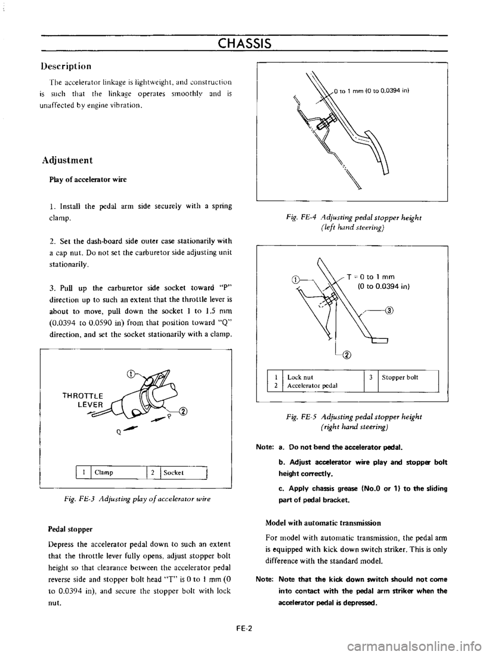
Pull
up
the
carburetor
side
socket
toward
P
direction
up
to
such
an
extent
that
the
throttle
lever
is
about
to
move
pull
down
the
socket
I
to
1
5
mm
0
0394
to
0
0590
in
frorn
that
position
toward
Q
direction
and
set
the
socket
stationarily
with
a
clamp
THROTTLE
LEVER
Q
I
I
I
Clamp
I
2
I
Sockel
Fig
FJ
3
Adjusting
play
of
a
ccelerator
wire
Pedal
stopper
Depress
the
accelerator
pedal
down
to
such
an
extent
that
the
throttle
lever
fully
opens
adjust
stopper
bolt
height
so
that
clearance
between
the
accelerator
pedal
reverse
side
and
stopper
bolt
head
T
is
0
to
I
mm
0
to
0
03Q4
in
and
secure
the
stopper
bolt
with
lock
nut
Fig
FE
4
1djusting
pedal
stopper
height
left
hand
steering
T
0
to
1
mm
0
to
0
0394
in
@
I
I
Lo
k
nut
2
Accelerator
pedal
I
3
I
Stopper
bolt
Fig
FE
5
Adjusting
pedal
stopper
height
right
hand
steering
Note
8
Do
not
bend
the
accelerator
pedal
b
Adjust
accelerator
wire
play
and
stopp
bolt
height
correctly
c
Apply
chassis
grease
No
a
or
1
to
the
sliding
part
of
pedal
bracket
Model
with
automatic
transmission
For
model
with
automatic
transmission
the
pedal
ann
is
equipped
with
kick
down
switch
striker
This
is
only
difference
with
the
standard
model
Note
Note
that
the
kick
down
switch
should
not
come
into
contact
with
the
pedal
arm
striker
when
the
accelerator
pedal
is
depressed
FE
2
Page 204 of 513

BODY
HOOD
CONTENTS
REMOVAL
AND
INSTAllATION
Removal
Installation
SF
14
SF
14
SF
14
REMOVAL
AND
INSTALLATION
Removal
Disconnect
the
windshield
washer
hose
at
the
nozzle
2
In
order
to
protect
the
hood
from
damaging
place
rag
in
both
sides
of
the
hood
rear
end
loosen
the
hood
hinge
installation
bolts
and
remove
the
hood
supporting
it
from
both
sides
as
shown
in
the
following
figure
Two
workers
are
required
Fig
BF
16
Removing
hood
hinge
I
i
7
r
r
o
r
il
Zc
h
2
Fig
BF
17
Remvoing
hood
HOOD
lOCK
Removal
Adjustment
Lubrication
Installation
SF
14
SF
14
SF
15
SF
16
Install
the
hood
in
reverse
sequence
of
removal
carefully
so
that
the
hood
is
flush
with
the
fender
top
and
clearance
between
the
hood
and
fender
is
aligned
evenly
toward
overall
circumferenc
e
of
the
hood
when
the
hood
is
closed
HOOD
LOCK
@
OJ
d
@
Q
o
1
Dovetail
bolt
2
Dovetail
bolt
retaining
nut
3
Spring
4
Safety
catch
lever
5
Female
lever
6
Spring
7
Hood
lock
control
lever
8
Rubber
grommet
Fig
BF
18
Hood
lock
mechanism
Removal
I
Remove
the
radiator
grille
loosen
the
installation
bolts
and
remove
the
male
side
of
the
hood
lock
2
Disconnect
the
hood
lock
wire
from
the
female
side
of
the
hood
lock
and
remOve
the
female
side
of
the
hood
lock
BF
14
Page 205 of 513
BODY
Fig
BF
19
R
g
male
side
of
the
hood
lock
Fig
BF
20
Removing
female
side
of
the
hood
lock
3
Remove
three
screws
and
remove
the
hood
lock
control
lever
Fig
BF
21
Removing
hood
lock
control
lever
Adjustment
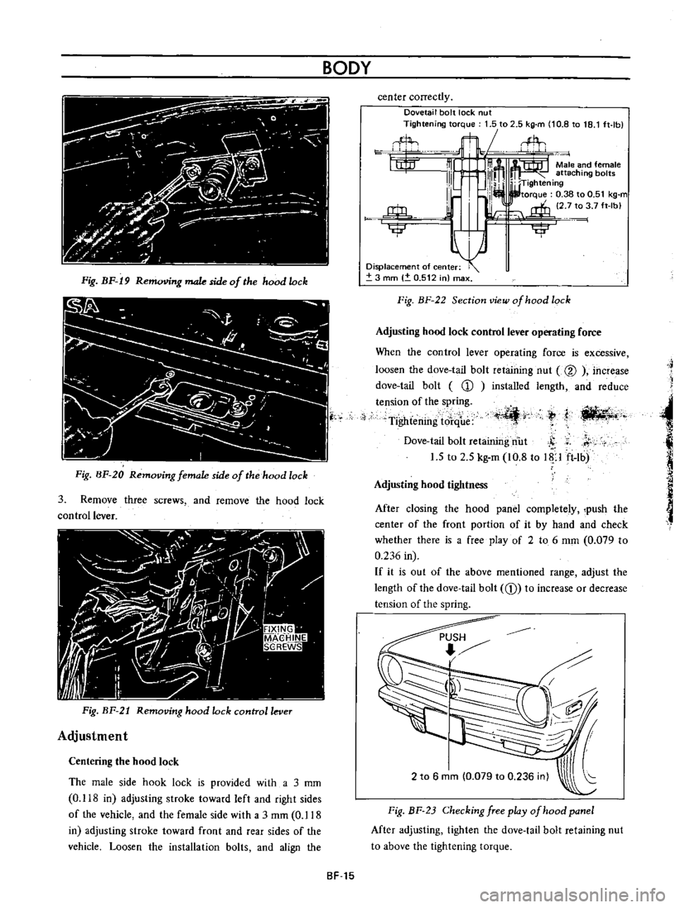
Centering
the
hood
lock
The
male
side
hook
lock
is
provided
with
a
3
mm
0
118
in
adjusting
stroke
toward
left
and
right
sides
of
the
vehicle
and
the
female
side
with
a
3
rnm
0
118
in
adjusting
stroke
toward
front
and
rear
sides
of
the
vehicle
Loosen
the
installation
bolts
and
align
the
center
correctly
Dovetail
bolt
lock
nut
Tightening
torque
1
5
to
2
5
kg
m
10
8
to
18
1
ft
lb
flL
t1t
m
m
Male
and
female
111
l
111m
attaching
bol
W
TIghtening
I
lb
I
I
torque
0
38
to
0
51
kg
m
l
i
2
7
to
3
7
ft
Ibl
j
rffi
u
Ilillr
iji
Displacement
of
center
3
mm
0
512
in
max
Fig
BF
22
Section
view
of
hood
lock
Adjusting
hood
lock
control
lever
operating
force
When
the
control
lever
operating
force
is
excessive
loosen
the
dove
tail
bolt
retaining
nut
@
increase
dove
tail
bolt
CD
installed
length
and
reduce
tension
of
the
spring
Tightening
tore
ue
t
I
ili
4r
ti
llt4
t
j
Dove
tail
bolt
retaining
nut
S
r
1
5
to
2
5
kg
m
10
8
to
Up
ft
lb
Adjusting
hood
tightness
After
closing
the
hood
panel
completely
push
the
center
of
the
front
portion
of
it
by
hand
and
check
whether
there
is
a
free
play
of
2
to
6
mm
0
079
to
0
236
in
If
it
is
out
of
the
above
mentioned
range
adjust
the
length
of
the
dove
tail
bolt
CD
to
increase
or
decrease
tension
of
the
spring
2
to
6
mm
0
079
to
0
236
inl
Fig
BF
23
Checking
free
play
of
hood
panel
After
adjusting
tighten
the
dove
tail
bolt
retaining
nut
to
above
the
tightening
torque
SF
15
Page 210 of 513
BODY
SEDAN
AND
COUPE
CD
@
h
r
1
@
@
II
I
Trunk
lid
2
Trunk
lid
lock
assembly
13
I
Trunk
lid
weatherstrip
4
Hinge
fixing
pin
15
I
Trunk
lid
hinge
6
Striker
assembly
Fig
BF
35
Trunk
lid
and
hinge
construction
Sedan
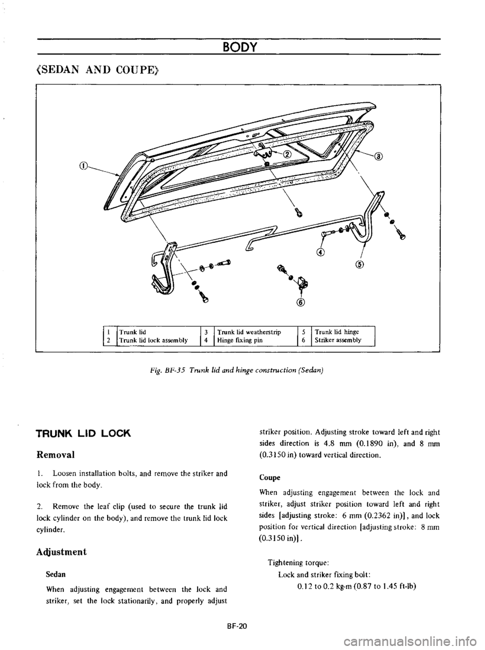
Removal
striker
position
Adjusting
stroke
toward
left
and
right
sides
direction
is
4
8
mm
0
1890
in
and
8
mm
0
3150
in
toward
vertical
direction
TRUNK
LID
LOCK
1
Loosen
installation
bolts
and
remove
the
striker
and
lock
from
the
body
Coupe
When
adjusting
engagement
between
the
lock
and
striker
adjust
striker
position
toward
left
and
right
sides
adjusting
stroke
6
mm
0
2362
in
and
lock
position
for
vertical
direction
adjusting
stroke
8
mm
0
3150
in
2
Remove
the
leaf
clip
used
to
secure
the
trunk
lid
lock
cylinder
on
the
body
and
remove
the
trunk
lid
lock
cylinder
Adjustment
When
adjusting
engagement
between
the
lock
and
striker
set
the
lock
stationarily
and
properly
adjust
Tightening
torque
Lock
and
striker
fIxing
bolt
0
12
to
0
2
kg
m
0
87
to
I
45
ft
Ib
Sedan
SF
20
Page 212 of 513
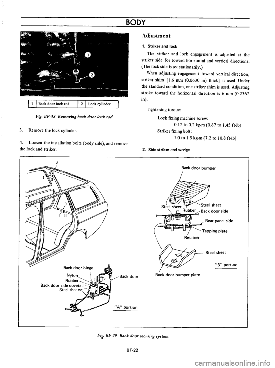
I
1
I
Back
door
lock
rod
I
2
I
Lock
cylinder
Fig
BF
38
Removing
back
door
lock
rod
3
Remove
the
lock
cylinder
4
Loosen
the
installation
bolts
body
side
and
remove
the
lock
and
striker
A
Back
door
hinge
Nylon
A
ubber
Back
door
side
dovetail
Steel
sheets
Back
door
A
portion
BODY
Adjustment
1
Striker
and
lock
The
striker
and
lock
engagement
is
adjusted
at
the
striker
side
for
toward
horizontal
and
vertical
directions
The
lock
side
is
sel
stationariIy
When
adjusting
engagement
toward
vertical
direction
striker
shim
1
6
mm
0
0630
in
thick
is
used
Under
the
standard
condition
one
striker
shim
is
used
Adjusting
stroke
toward
the
horizontal
direction
is
6
mm
0
2362
in
Tightening
torque
Lock
fIXing
machine
screw
0
12
to
0
2
kg
m
0
87
to
I
45
ft
lb
Striker
fIxing
bolt
1
0
to
1
5
kg
m
7
2
to
10
8
ft
Ib
2
Side
striker
and
wedge
Back
door
bumper
r
Steel
sheet
Steel
sheet
Rubber
Back
door
side
I
Rear
panel
side
Tapping
plate
Steel
sheet
8
portion
Back
door
bumper
plate
FiS
BF
39
Back
door
securing
system
SF
22
Page 213 of 513
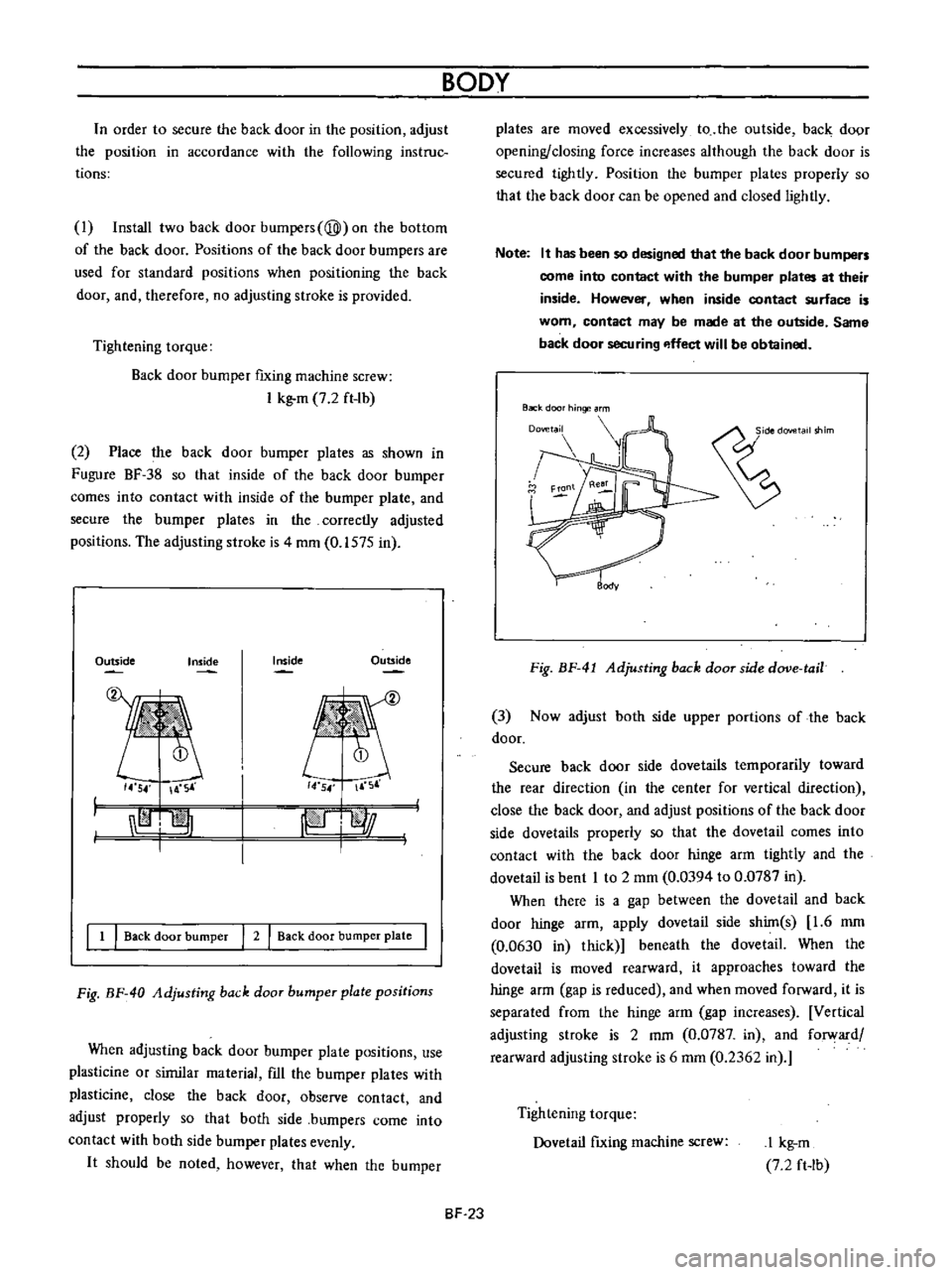
n
order
to
secure
the
back
door
in
the
position
adjust
the
position
in
accordance
with
the
following
instruc
tions
I
Install
two
back
door
bumpers
@
on
the
bottom
of
the
back
door
Positions
of
the
back
door
bumpers
are
used
for
standard
positions
when
positioning
the
back
door
and
therefore
no
adjusting
stroke
is
provided
Tightening
torque
Back
door
bumper
fixing
machine
screw
I
kg
m
7
2
ft
lb
2
Place
the
back
door
bumper
plates
as
shown
in
Fugure
BF
38
so
that
inside
of
the
back
door
bumper
comes
into
contact
with
inside
of
the
bumper
plate
and
secure
the
bumper
plates
in
the
correctly
adjusted
positions
The
adjusting
stroke
is
4
mm
0
1575
in
Outside
Inside
Outside
Inside
14
54
A
S
14
54
F
r
I
I
jpiJ
l
l
j
I
1
I
Back
door
bumper
I
2
I
Back
door
bumper
plate
I
Fig
BF
40
Adjusting
back
door
bumper
plate
positions
When
adjusting
back
door
burnper
plate
positions
use
plasticine
or
sirnilar
material
fIll
the
bumper
plates
with
plasticine
close
the
back
door
observe
contact
and
adjust
properly
so
that
both
side
bumpers
come
into
contact
with
both
side
bumper
plates
evenly
It
should
be
noted
however
that
when
the
bumper
BODY
BF
23
plates
are
moved
excessively
to
the
outside
back
door
opening
closing
force
increases
although
the
back
door
is
secured
tightly
Position
the
bumper
plates
properly
so
that
the
back
door
can
be
opened
and
closed
lightly
Note
It
has
been
so
designed
that
the
back
door
bumpers
come
into
contact
with
the
bumper
plates
at
their
inside
However
when
inside
contact
surface
is
worn
contact
may
be
made
at
the
outside
Same
back
door
securing
p
ffect
will
be
obtained
Back
door
hinge
rm
Fig
BF
41
Adjusting
back
door
side
dove
tail
3
Now
adjust
both
side
upper
portions
of
the
back
door
Secure
back
door
side
dovetails
temporarily
toward
the
rear
direction
in
the
center
for
vertical
direction
close
the
back
door
and
adjust
positions
of
the
back
door
side
dovetails
properly
so
that
the
dovetail
comes
into
contact
with
the
back
door
hinge
arm
tightly
and
the
dovetail
is
bent
I
to
2
mm
0
0394
to
0
0787
in
When
there
is
a
gap
between
the
dovetail
and
back
door
hinge
arm
apply
dovetail
side
shim
s
1
6
mm
0
0630
in
thick
beneath
the
dovetail
When
the
dovetail
is
moved
rearward
it
approaches
toward
the
hinge
arm
gap
is
reduced
and
when
moved
forward
it
is
separated
from
the
hinge
arrn
gap
increases
Vertical
adjusting
stroke
is
2
mm
0
0787
in
and
forward
rearward
adjusting
stroke
is
6
mm
0
2362
in
Tightening
torque
Dovetail
fIxing
machine
screw
I
kg
m
7
2
ft
Ib