1973 DATSUN B110 tow
[x] Cancel search: towPage 88 of 513
CHASSIS
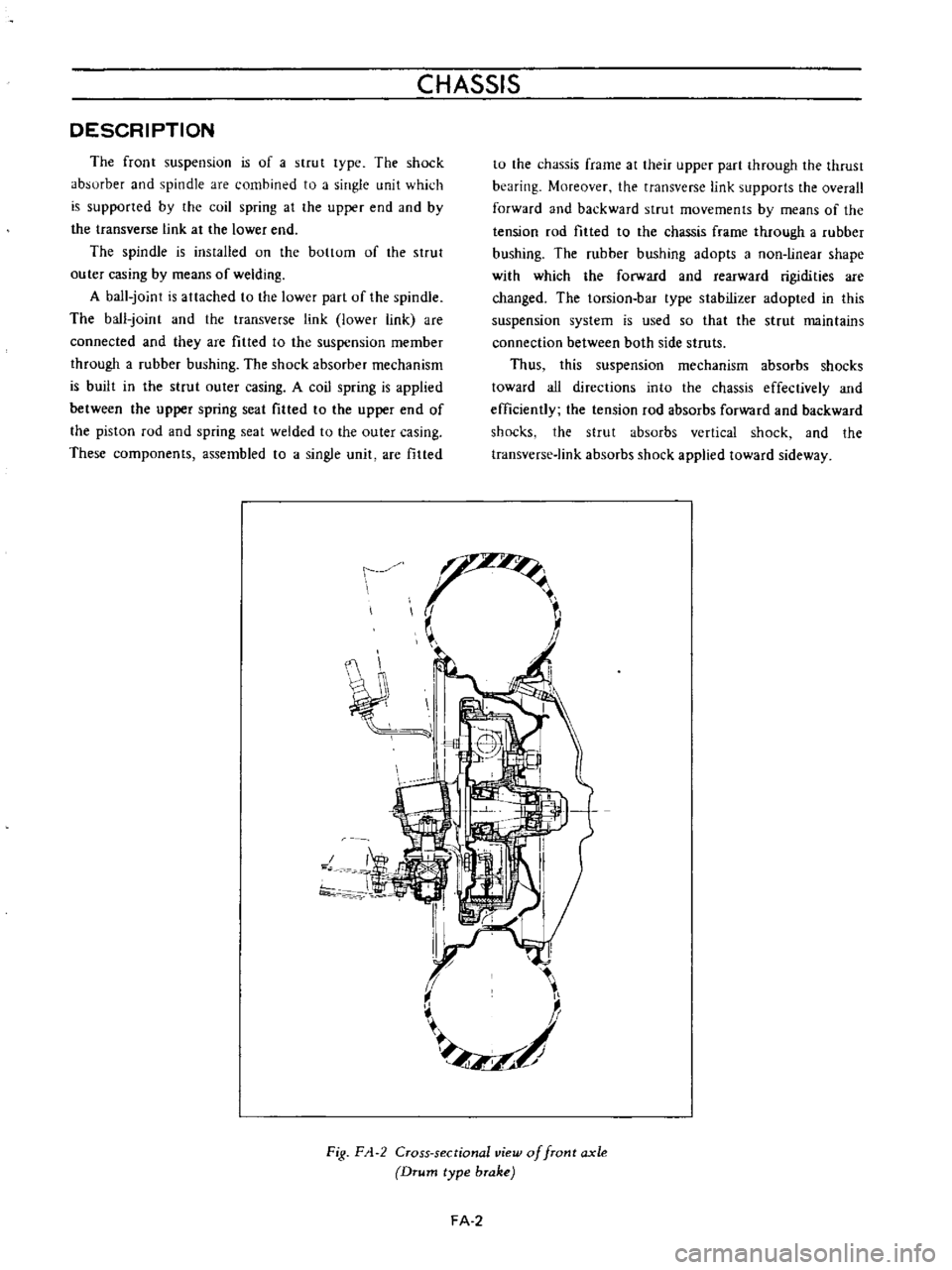
DESCRIPTION
The
front
suspension
is
of
a
strut
lype
The
shock
absurber
and
spindle
are
combined
to
a
single
unit
which
is
supported
by
the
coil
spring
at
the
upper
end
aod
by
the
transverse
link
at
the
lower
end
The
spindle
is
ins
tailed
on
the
bottom
of
the
strut
outer
casing
by
means
of
welding
A
ball
joint
is
attached
to
the
lower
part
of
the
spindle
The
ball
joint
and
the
transverse
link
lower
link
are
connected
and
they
are
fitted
to
the
suspension
member
through
a
rubber
bushing
The
shock
absorber
mechanism
is
built
in
the
strut
outer
casing
A
coil
spring
is
applied
between
the
upper
spring
seat
filled
to
the
upper
end
of
the
piston
rod
and
spring
seat
welded
to
the
outer
casing
These
components
assembled
to
a
single
unit
are
fitted
tu
the
chassis
frame
at
their
upper
part
through
the
thrust
bearing
Moreover
the
transverse
link
supports
the
overall
forward
and
backward
strut
movements
by
means
of
the
tension
rod
filled
to
the
chassis
frame
through
a
rubber
bushing
The
rubber
bushing
adopts
a
non
linear
shape
with
which
the
forward
and
rearward
rigidities
are
changed
The
torsion
bar
type
stabilizer
adopted
in
this
suspension
system
is
used
so
that
the
strut
maintains
connection
between
both
side
struts
Thus
this
suspension
mechanism
absorbs
shocks
toward
all
directions
into
the
chassis
effectively
and
efficiently
the
tension
rod
absorbs
forward
and
backward
shocks
the
strut
absorbs
vertical
shock
and
the
transverse
link
absorbs
shock
applied
toward
sideway
t
J
f
II
L
II
I
7
f
1
I
Fig
F
1
2
Cross
sectional
view
of
front
axle
Drum
type
brake
FA
2
Page 97 of 513
FRONT
AXLE
FRONT
SUSPENSION
t
t
Fig
FA
26
Returning
wheel
bearing
lock
nut
4
Turn
the
wheel
hub
a
few
turns
both
clockwise
and
counterclockwise
again
to
allow
the
bearing
breaking
in
measure
bearing
rotation
starting
torque
apply
a
cotter
pin
to
secure
the
nut
if
the
measured
starting
torque
is
within
the
rated
value
and
install
the
hub
cap
hub
cap
Wheel
bearing
rotation
starting
torque
9
0
kg
cm
7
8
in
1b
4
0
kg
cm
3
4
7
in
1b
At
the
hub
bolt
1
57
kg
3
461b
New
bearing
0
7
kg
1
54lb
Used
bearing
No
slackness
should
exist
toward
the
axis
direction
New
bearing
Used
bearing
J
o
i
@
j
Be
sure
to
remove
the
brake
pad
Disc
type
brake
Correctly
measure
starting
force
toward
tangential
direction
against
the
hub
bolt
Fig
FA
27
Measuring
wheel
bearing
ro
ation
starting
torque
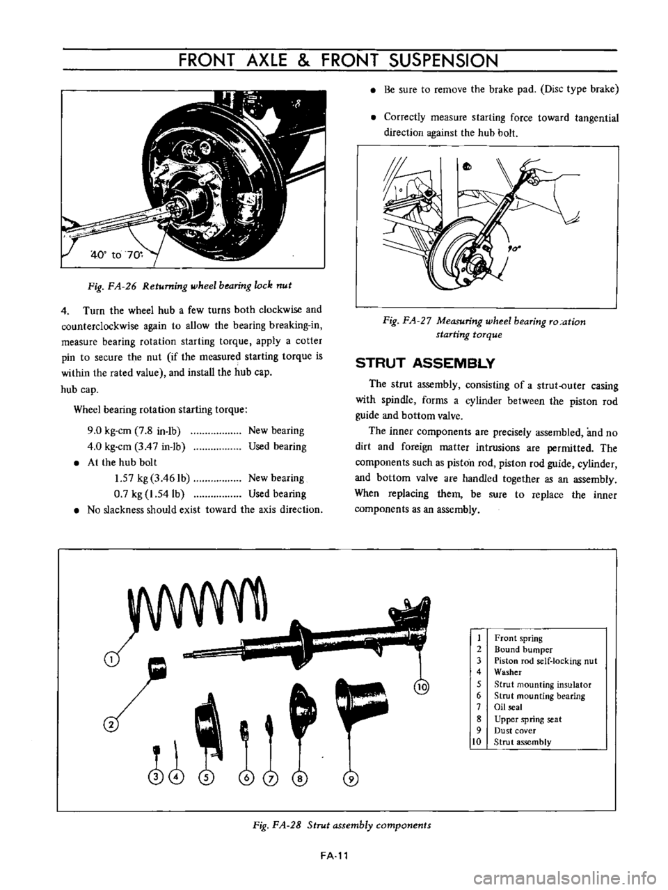
STRUT
ASSEMBLY
The
strut
assembly
consisting
of
a
strut
outer
casing
with
spindle
forms
a
cylinder
between
the
piston
rod
guide
and
bottom
valve
The
inner
components
are
precisely
assembled
and
no
dirt
and
foreign
matter
intrusions
are
permitted
The
components
such
as
piston
rod
piston
rod
guide
cylinder
and
bottom
valve
are
handled
together
as
an
assembly
When
replacing
them
be
sure
to
replace
the
inner
components
as
an
assembly
1
2
3
4
5
6
7
8
9
10
Front
spring
Bound
bumper
Piston
rod
self
locking
nut
Washer
Strut
mounting
insulator
Strut
mounting
bearing
Oil
seal
Upper
spring
seat
Dust
cover
Strut
assembly
Fig
FA
28
Strut
assembly
components
FA
l1
Page 100 of 513
CHASSIS
Fig
FA
35
Removing
O
ring
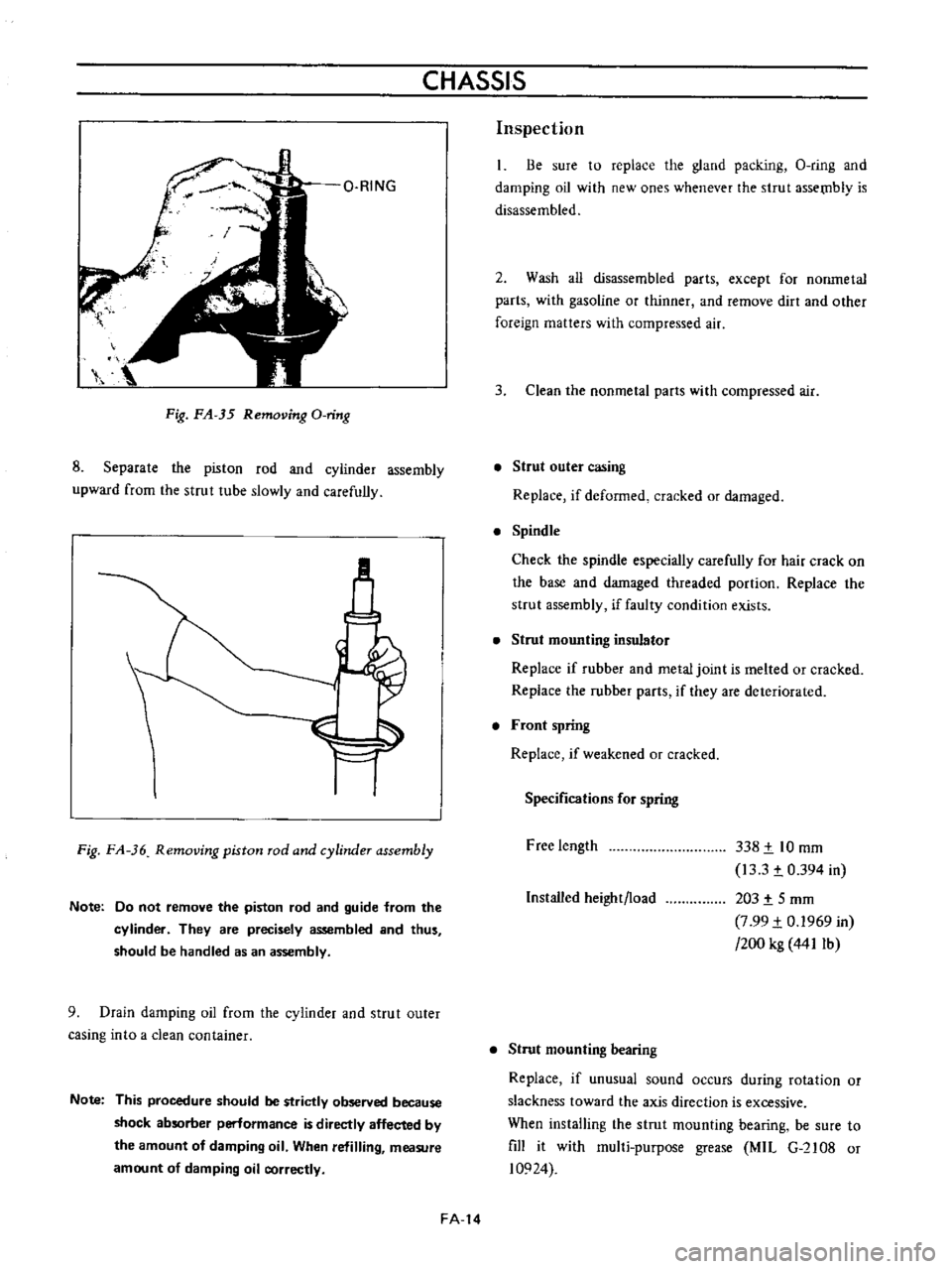
8
Separate
the
piston
rod
and
cyiinder
assembly
upward
from
the
strut
tube
slowly
and
carefully
M
Fig
FA
36
Removing
piston
rod
and
cylinder
assembly
Note
Do
not
remove
the
piston
rod
and
guide
from
the
cylinder
They
are
precisely
assembled
and
thus
should
be
handled
as
an
assembly
9
Drain
damping
oil
from
the
cylinder
and
strut
outer
casing
into
a
clean
container
Note
This
procedure
should
be
strictly
observed
because
shock
absorber
perlormance
is
directly
affected
by
the
amount
of
damping
oil
When
refilling
measure
amount
of
damping
oil
correctly
FA
14
Inspection
Be
sure
to
replace
the
gland
packing
O
ring
and
damping
oil
with
new
ones
whenever
the
strut
assetnb1y
is
disassembled
2
Wash
all
disassembled
parts
except
for
nonmetal
parts
with
gasoline
or
thinner
and
remove
dirt
and
other
foreign
matters
with
compressed
air
3
Clean
the
nonmetal
parts
with
compressed
air
Strut
outer
casing
Replace
if
deformed
cracked
or
damaged
Spindle
Check
the
spindle
especially
carefully
for
hair
crack
on
the
base
and
damaged
threaded
portion
Replace
the
strut
assembly
if
faulty
condition
exists
Strut
mounting
insulator
Replace
if
rubber
and
metal
joint
is
melted
or
cracked
Replace
the
rubber
parts
if
they
are
deteriorated
Front
spring
Replace
if
weakened
or
cracked
Specifications
for
spring
Free
length
338
t
10
mm
13
3
t
0
394
in
203
t
5
mm
7
99
t
0
1969
in
200
kg
441Ib
Installed
height
load
Strut
mounting
bearing
Replace
if
unusual
sound
occurs
during
rotation
or
slackness
toward
the
axis
direction
is
excessive
When
installing
the
strut
mounting
bearing
be
sure
to
fill
it
with
mul1i
purpose
grease
MIL
G
2108
or
10924
Page 105 of 513
FRONT
AXLE
FRONT
SUSPENSION
I
ST36721
000
ST36722000
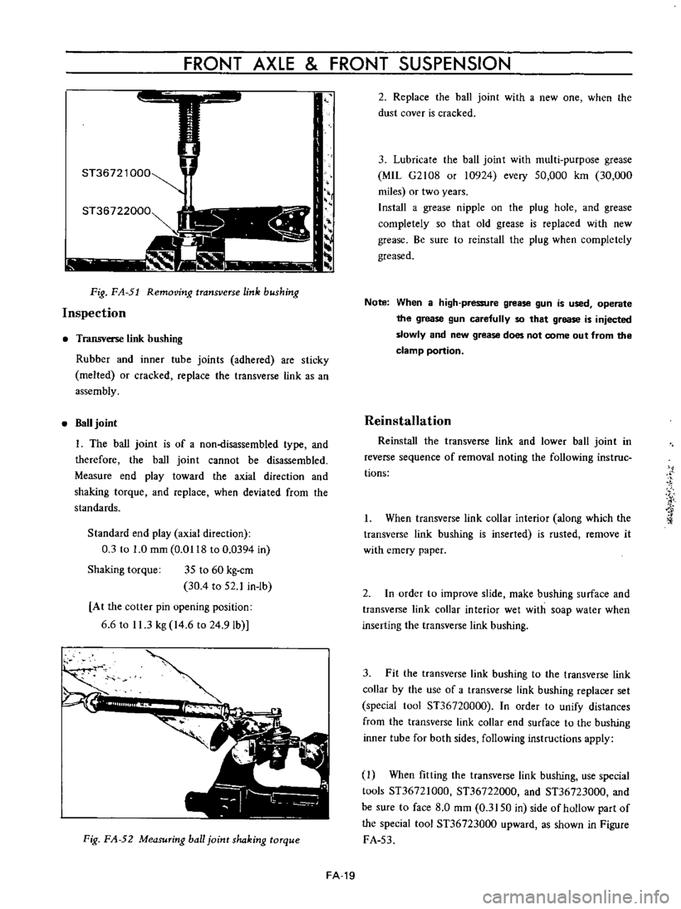
Fig
FA
51
Removing
transverse
link
bushing
Inspection
Transverse
link
bushing
Rubber
and
inner
tube
joints
adhered
are
sticky
melted
or
cracked
replace
the
transverse
link
as
an
assembly
Ball
joint
I
The
ball
joint
is
of
a
non
disassembled
type
and
therefore
the
ball
joint
cannot
be
disassembled
Measure
end
play
toward
the
axial
direction
and
shaking
torque
and
replace
when
deviated
from
the
standards
Standard
end
play
axial
direction
0
3
to
1
0
mm
0
0118
to
0
0394
in
Shaking
torque
35
to
60
kg
cm
30
4
to
52
1
in
ib
At
the
cotter
pin
opening
position
6
6
to
11
3
kg
14
6
to
24
9Ib
I
Fig
FA
52
Measuring
ball
joint
shaking
torque
2
Replace
the
ball
joint
with
a
new
one
when
the
dust
cover
is
cracked
3
Lubricate
the
ball
joint
with
multi
purpose
grease
MIL
G2108
or
10924
every
50
000
km
30
000
miles
or
two
years
Install
a
grease
nipple
on
the
plug
hole
and
grease
completely
so
that
old
grease
is
replaced
with
new
grease
Be
sure
to
reinstall
the
plug
when
completely
greased
Note
When
a
high
pressure
grease
gun
is
used
operate
the
grease
gun
carefully
so
that
grease
is
injected
slowly
and
new
grease
does
not
come
out
from
the
clamp
portion
Reinstallation
Reinstall
the
transve
l
e
link
and
lower
ball
joint
in
reverse
sequence
of
removal
noting
the
following
ins
true
tions
I
When
transverse
link
collar
interior
along
which
the
transverse
link
bushing
is
inserted
is
rusted
remove
it
with
emery
paper
2
In
order
to
improve
slide
make
bushing
surface
and
transverse
link
collar
interior
wet
with
soap
water
when
inserting
the
transverse
link
bushing
3
Fit
the
transverse
link
bushing
to
the
transverse
link
collar
by
the
use
of
a
transverse
link
bushing
replacer
set
special
1001
ST36720000
In
order
to
unify
distances
from
the
transverse
link
collar
end
surface
to
the
bushing
inner
tube
for
both
sides
following
instructions
apply
1
When
fitting
the
transve
l
e
link
bushing
use
special
tools
ST36721000
ST36722000
and
ST36723000
and
be
sure
to
face
8
0
mm
0
3150
in
side
of
hollow
part
of
the
special
tool
ST36723000
upward
as
shown
in
Figure
FA
53
FA
19
Page 120 of 513
REAR
AXLE
REAR
SUSPENSION
DESCRIPTION
Rear
suspension
consists
of
semi
elliptic
leaf
springs
telescopic
hydraulic
shock
absorbers
and
rubber
bumpers
The
rear
spring
center
pin
is
off
set
110
mm
4
33
in
toward
the
front
from
the
center
of
the
spring
This
is
done
to
reduce
spring
wind
up
and
to
decrease
the
arc
while
the
rear
wheel
swings
through
Thereby
minimizing
the
possibility
of
the
rear
suspension
effecting
vehicle
stability
Iso
clamp
devices
are
used
for
attaching
the
axle
housing
to
the
spring
The
leaf
springs
shock
absorbers
and
rear
axle
housing
are
mounted
on
rubber
bushings
at
each
end
to
minimize
noise
and
vibration
of
the
transmission
to
the
car
body
and
passenger
compartment
REAR
SPRING
Removal
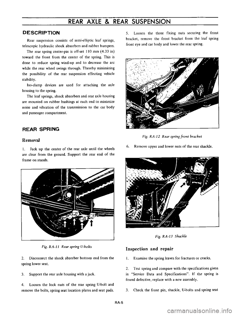
1
Jack
up
the
center
of
the
rear
axle
until
the
wheels
are
clear
from
the
ground
Support
the
rear
end
of
the
frame
on
stands
Fig
RA
l1
Rear
spring
U
bo
ts
2
Disconnect
the
shock
absorber
bottom
end
from
the
spring
lower
seat
3
Support
the
rear
axle
housing
with
a
jack
4
Loosen
the
lock
nuts
of
the
rear
spring
U
bolt
and
remove
the
bolts
spring
seat
location
plates
and
seat
pads
5
Loosen
the
three
fixing
nuts
securing
the
front
bracket
remove
the
front
bracket
from
the
leaf
spring
front
eye
and
car
body
and
lower
the
rear
spring
Fig
RA
12
Rear
spring
front
bracket
6
Remove
upper
and
lower
nuts
of
the
rear
shackle
Fig
RA
13
Shackle
Inspection
and
repair
1
Examine
the
spring
leaves
for
fractures
or
cracks
2
Test
spring
and
compare
with
the
specifications
given
in
Service
Data
and
Specifications
If
the
spring
is
found
defective
replace
with
a
new
assembly
3
Check
the
front
pin
shackle
U
bolts
and
spring
seat
RA
5
Page 131 of 513

Tightening
torque
3
way
connector
1
5
to
1
8
kg
m
10
8
to
13
0
ft
lh
1
5
to
1
8
kg
m
10
8
to
13
0
ft
lh
1
5
to
1
8
kg
m
10
8
to
13
0
ft
lb
0
7
to
0
9
kg
m
5
1
to
6
5
ft
1b
Master
cylinder
Brake
hose
Air
bleeder
5
Fill
the
master
cylinder
brake
fluid
reservoir
with
brake
fluid
and
perform
air
bleeding
complele1y
Note
a
Do
not
use
brake
fluid
other
than
specified
b
The
specified
brake
fluid
is
used
for
both
single
and
tandem
type
master
cylinders
6
Upon
completion
of
air
bleeding
make
sure
that
the
brake
operates
correctly
and
check
the
brake
tube
and
hose
connectors
for
fluid
leaking
Fully
depress
the
brake
pedal
continue
to
depress
the
brake
pedal
for
several
seconds
and
make
sure
that
no
brake
fluid
leaks
from
any
part
of
the
brake
line
Replace
defective
part
if
required
Brake
line
pressure
differential
warning
light
switch
A
warning
light
is
located
on
the
instrument
panel
to
warn
the
driver
when
a
pressure
difference
of
13
to
17
kg
cm2
185
to
2421bJsq
in
exists
between
the
front
and
rear
b
rake
systems
A
hydraulically
actuated
warning
light
switch
is
located
in
the
engine
compartment
Both
front
and
rear
brake
systems
are
connected
to
this
switch
assembly
When
a
pressure
difference
of
13
to
17
kgJcm2
185
to
242
lbJsq
in
occurs
between
the
front
and
rear
brake
systems
the
valves
will
shuttle
toward
the
side
with
the
low
pressure
The
valve
contacts
with
the
switch
terminal
BRAKE
the
ground
circuit
for
the
warning
light
is
completed
and
thus
the
warning
light
lights
In
this
case
correct
the
hydraulic
brake
problem
and
bleed
the
brakes
Check
the
warning
light
switch
assembly
for
a
proper
operation
Check
the
switch
assembly
for
fluid
leakage
Note
Do
not
attempt
to
repair
switch
for
any
reason
replace
switch
assembly
completely
1
To
front
brake
L
H
2
From
master
cylinder
F
3
From
master
cylinder
R
4
To
rear
brake
L
B
R
M
5
To
front
brake
R
H
Fig
BR
12
Warning
light
switch
r
I
@
I
I
3
I
Valve
assembly
4
Piston
load
spring
Wire
terminal
Brake
tube
Fig
BR
13
Sectional
view
of
warning
light
switch
BR
7
Page 143 of 513
Removal
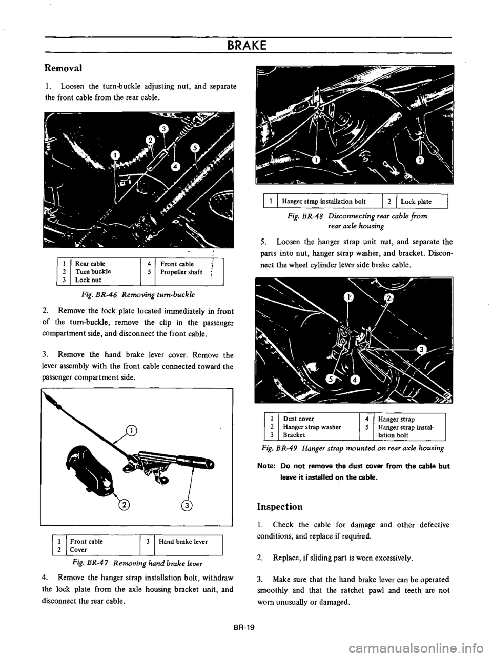
Loosen
the
turn
buckle
adjusting
nut
and
separate
the
front
cable
from
the
rear
cable
1
Rear
cable
2
Turn
buckle
3
Lock
nut
4
Front
cable
5
Propeller
shaft
Fig
BR
46
Removing
turn
buckle
2
Remove
the
lock
plate
located
immediately
in
front
of
the
turn
buckle
remove
the
clip
in
the
passenger
compartment
side
and
disconnect
the
front
cable
3
Remove
the
hand
brake
lever
cover
Remove
the
lever
assembly
with
the
front
cable
connected
toward
the
passenger
compartment
side
1
I
Front
cable
2
Cover
I
3
Hand
brake
lever
Fig
BR
47
Removing
hand
brake
lever
4
Remove
the
hanger
strap
installation
bolt
withdraw
the
lock
plate
from
the
axle
housing
brncket
unit
and
disconnect
the
rear
cable
BRAKE
I
1
I
Hanger
strap
installation
bolt
r
2
I
Lock
plate
Fig
BR
48
Disconnecting
Tear
cable
from
rear
axle
housing
5
Loosen
the
hanger
slrap
unit
nut
and
separate
the
parts
into
nut
hanger
strap
washer
and
bracket
Discon
nect
the
wheel
cylinder
lever
side
brake
cable
r
v
I
j
1
r
1fil
lt
J
l
1
1
I
c
2
1
Dust
cover
2
Hanger
strap
washer
3
Bracket
4
Hanger
strap
5
Hanger
strap
instal
lation
bolt
Fig
BR
49
Hanger
strap
mounted
on
rear
axle
housing
Note
Do
not
remove
the
dust
cover
from
the
cable
but
leave
it
installed
on
the
cable
Inspection
Check
the
cable
for
damage
and
other
defective
conditions
and
replace
if
required
2
Replace
if
sliding
part
is
worn
excessively
3
Make
sure
that
the
hand
brake
lever
can
be
operated
smoothly
and
that
the
ratchet
pawl
and
teeth
are
not
wom
unusually
or
damaged
BR
19
Page 163 of 513
STEERING
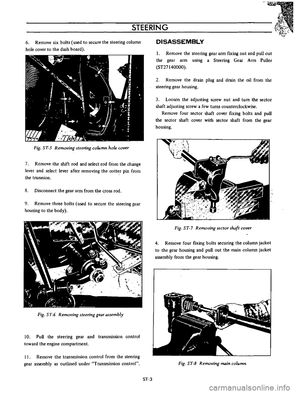
6
Remove
six
bolts
used
to
secure
the
steering
column
hole
cover
to
the
dash
board
Fig
ST
5
Removing
steering
column
hole
cover
7
Remove
the
shift
rod
and
select
rod
from
the
change
lever
and
select
lever
after
removing
the
cotter
pin
from
the
trunnion
8
Disconnect
the
gear
arm
from
the
crOSS
rod
9
Remove
three
bolts
used
to
secure
the
steering
gear
housing
to
the
body
Fig
ST
6
Removing
steering
gear
assembly
10
Pull
the
steering
gear
and
transmission
control
toward
the
engine
compartment
11
Remove
the
transmission
control
from
the
steering
gear
assembly
as
outlined
under
Transmission
control
DISASSEMBLY
1
Remove
the
steering
gear
arm
fIxing
nut
and
pull
out
the
gear
arm
using
a
Steering
Gear
Arm
Puller
ST27140000
2
Remove
the
drain
plug
and
drain
the
oil
from
the
steering
gear
housing
3
Loosen
the
adjusting
screw
nut
and
turn
the
sector
shaft
adjusting
screw
a
few
turns
counterclockwise
Remove
four
sector
shaft
cover
fIxing
bolts
and
pull
the
sector
shaft
cover
with
sector
shaft
from
the
gear
housing
t
I
gJ
I
I
Fig
ST
7
Removing
sector
shaft
cover
4
Remove
four
fIxing
bolts
securing
the
column
jacket
to
the
gear
housing
and
pull
out
the
main
column
jacket
assembly
from
the
gear
housing
Fig
ST
8
Removing
main
column
ST
3