1973 DATSUN B110 tow
[x] Cancel search: towPage 307 of 513
ENGINE
operating
mechanism
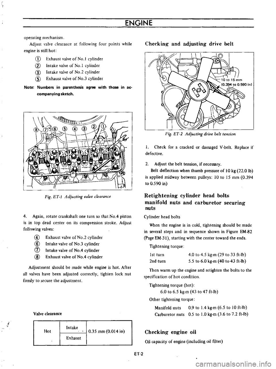
Adjust
valve
clearance
at
following
four
points
while
engine
is
still
hot
G
Exhaust
valve
of
No
1
cylinder
CV
Intake
valve
of
No
1
cylinder
CID
Intake
valve
of
No
2
cylinder
CID
Exhaust
valve
of
No
3
cylinder
Note
Numbers
in
parenthesis
agree
with
those
in
ac
companying
sketch
I
Fig
BY
1
Adjusting
valve
clearance
4
Again
rotate
crankshaft
one
turn
so
that
No
4
piston
is
in
top
dead
ce
lter
on
its
compression
stroke
Adjust
follnwing
valves
@
Exhaust
valve
of
No
2
cylinder
@
Intake
valve
of
No
3
cylinder
f
Intake
valve
of
No
4
cylinder
@
Exhaust
valve
of
No
4
cylinder
Adjustment
should
be
made
while
engine
is
hot
After
all
valves
have
been
adjusted
correctly
tighten
lock
nut
firmly
to
secure
the
adjustment
Vah
e
clearance
Hot
Intake
0
35
mm
0
014
in
Exhaust
Checking
and
adjusting
drive
belt
II
I
Fig
ET
2
Adjusting
drive
belt
tension
I
Check
for
a
cracked
or
damaged
V
belt
Replace
if
defective
2
Adjust
the
belt
tension
if
necessary
Belt
deflection
when
thumb
pressure
of
10
kg
22
0
lb
is
applied
midway
between
pulleys
10
to
15
mm
0
394
to
0
590
in
Retightening
cylinder
head
bolts
manifold
nuts
and
carburetor
securing
nuts
Cylinder
head
bolts
When
the
engine
is
in
cold
tightening
should
be
made
in
several
steps
and
in
sequence
shown
in
Figure
EM
82
page
EM
31
starting
with
the
center
toward
the
ends
Tightening
torque
1st
turn
2nd
turn
4
0
to
4
5
kg
m
29
to
33
ft
lb
5
5
to
6
0
kg
m
40
to
43
ft
lb
Then
warm
up
the
engine
and
retighten
the
bolts
to
the
specification
of
hot
condition
Tightening
torque
hot
6
0
to
6
5
kg
m
43
to
47
ft
lb
Other
tightening
torque
Manifold
nuts
0
9
to
14
kg
m
6
5
to
10
ft
lb
Carburetor
nuts
0
5
to
LO
kg
m
3
6
to
7
2
ft
lb
Checking
engine
oil
Oil
capacity
of
engine
including
oil
filter
ET
2
Page 312 of 513

EMISSION
CONTROL
AND
TUNE
UP
Fig
ET
11
Checking
spark
plug
gap
Checking
distributor
ignition
wiring
and
ignition
coil
Distributor
Check
centrifugal
advance
unit
for
loose
connection
or
improper
operation
If
it
is
not
operating
properly
the
trouble
may
be
due
to
a
sticky
spring
or
excessively
worn
parts
This
operation
needs
a
distributor
tester
As
to
inspection
procedure
and
reference
data
refer
to
relative
topic
under
Distributor
in
Section
EE
Page
EE
32
If
vacuum
advance
mechanism
fails
to
operate
proJr
erly
check
for
the
following
items
and
correct
the
trouble
as
required
1
Check
vacuum
inlet
for
signs
of
leakage
at
its
connection
If
necessary
retighten
or
replace
with
a
new
one
2
Check
vacuum
diaphragm
for
air
leak
If
leak
is
found
replace
diaphragm
with
a
new
one
3
Inspect
breaker
plate
for
smooth
moving
If
plate
does
not
move
smoothly
this
condition
could
be
due
to
sticky
steel
balls
or
pivot
Apply
grease
to
steel
balls
or
if
necessary
replace
breaker
plate
as
an
assembly
For
vacuum
advance
characteristics
refer
to
Distribu
tor
in
Section
EE
Page
EE
32
Ignition
wiring
Use
an
ohmmeter
to
check
resistance
of
secondary
cables
Disconnect
cables
from
spark
plugs
and
install
the
proper
adapter
between
cable
and
spark
plug
Remove
distributor
cap
from
the
distributor
with
secondary
cables
attached
Do
not
remove
the
cables
from
the
cap
Check
the
resistance
of
one
cable
at
a
time
Connect
the
ohmmeter
between
the
spark
plug
adapter
and
the
corresponding
electrode
inside
the
cap
If
resistance
is
more
than
30
000
ohms
remove
the
cable
from
the
cap
and
check
cable
resistance
only
If
the
resistance
is
still
more
than
30
000
ohms
replace
cable
assembly
T
I
II
Fig
ET
12
Checking
high
tension
cables
Ignition
coil
Check
ignition
coil
for
appearance
oil
leakage
or
performance
For
details
refer
to
Section
EE
Page
EE36
Checking
distributor
cap
and
rotor
Note
This
operation
is
to
be
performed
while
chekcing
distribuotr
points
Inspect
distributor
cap
for
cracks
and
flash
over
External
surfaces
of
all
parts
of
secondary
system
must
be
cleaned
to
reduce
possibility
of
voltage
loss
All
wires
should
be
removed
from
distributor
cap
and
coil
so
that
terminals
can
be
inspected
and
cleaned
Burned
or
corroded
terminals
indicate
that
wires
were
not
fully
seated
which
causes
arcing
between
end
of
wire
and
terminal
When
replacing
wires
in
terminal
be
sure
they
are
fully
seated
before
pushing
rubber
nipple
down
over
tower
Check
distributor
rotor
for
damage
and
distributor
cap
for
cracks
ET
7
Page 366 of 513
ENGINE
ST130300
1
EM156
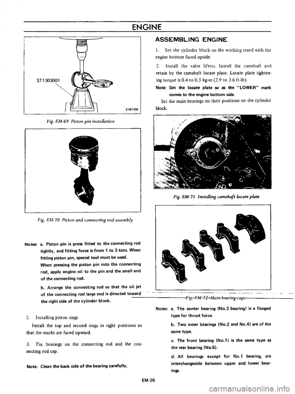
Fig
EM
69
Piston
pin
installation
Fig
EM
70
Piston
and
connecting
rod
assembly
Notes
8
Piston
pin
is
press
fitted
to
the
connecting
rod
tightly
and
fitting
force
is
from
1
to
3
tons
When
fitting
piston
pin
special
tool
must
be
used
When
pressing
the
piston
pin
into
the
connecting
rod
apply
engine
oil
to
the
pin
and
the
small
end
of
the
connecting
rod
b
Arrange
the
connecting
rod
so
that
the
oil
jet
of
the
connecting
rod
large
end
is
directed
toward
the
right
side
of
the
cylinder
block
2
Installing
piston
rings
Install
the
top
and
second
fings
in
right
positions
so
that
the
marks
are
faced
upward
3
Fix
bearings
on
the
connecting
rod
and
the
con
necting
rod
cap
Note
Clean
the
back
side
of
the
bearing
carefully
ASSEMBLING
ENGINE
Set
the
cylinder
block
on
the
working
stand
with
the
engine
bottom
faced
upside
2
Install
the
valve
lifters
Install
the
camshaft
and
retain
by
the
camshaft
locate
plate
Locate
plate
tighten
ing
torque
is
0
4
to
0
5
kg
m
2
9
to
3
6
ft
lb
Note
Set
the
locate
plate
so
as
the
LOWER
mark
comes
to
the
engine
bottom
side
Set
the
main
bearings
on
their
positions
on
the
cylinder
block
Fig
EM
71
Installing
camshaft
ocate
plate
Fig
E1U
7
2
lvlajn
betlrj
lg
cap
Notes
a
The
center
bearing
No
3
bearing
is
a
flanged
type
for
thrust
force
b
Two
inner
bearings
No
2
and
No
4
are
of
the
same
type
c
The
front
bearing
No
1
is
the
same
type
a
the
rear
bearing
No
5
d
All
bearings
except
for
No
1
bearing
are
interchangeable
between
upper
and
lower
bear
ings
EM
26
Page 367 of 513
ENGINE
MECHANICAL
3
Apply
engine
oil
to
the
main
bearing
surfaces
on
both
sides
of
the
cylinder
block
and
cap
Install
the
crankshaft
4
Install
the
main
bearing
cap
and
tighten
the
bolts
with
specified
torque
Tightening
torque
5
0
to
6
0
kg
m
36
to
43
ft
lb
Notes
a
Arrange
the
parts
so
that
the
arrow
mark
on
the
bearing
cap
is
faced
toward
the
front
of
the
engine
b
Prior
to
tightening
the
bearing
cap
bolts
place
the
bearing
cap
at
a
proper
position
by
shifting
the
crankshaft
in
the
axial
direction
c
Tighten
the
bearing
cap
bolts
gradually
in
separating
two
to
three
stages
and
outwardly
from
the
center
beari
ng
d
After
securing
the
bearing
cap
bolts
ascertain
that
the
crankshaft
can
be
easily
rotated
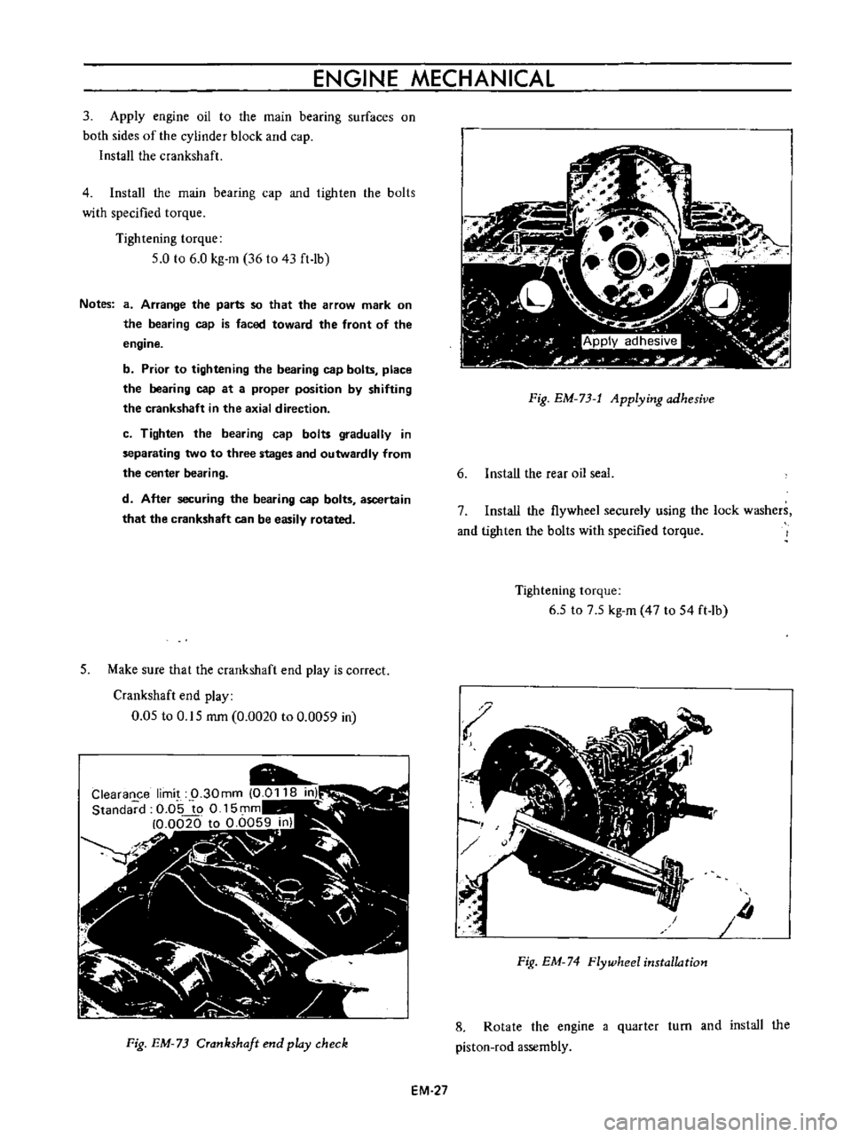
5
Make
sure
that
the
crankshaft
end
play
is
correct
Crankshaft
end
play
0
05
to
0
15
rom
0
0020
to
0
0059
in
Fig
EM
73
Crankshaft
end
play
check
EM
27
Fig
EM
73
t
Applying
adhesive
6
Install
the
rear
oil
seal
7
Install
the
flywheel
securely
using
the
lock
washers
and
tighten
the
bolts
with
specified
torque
Tightening
torque
6
5
to
7
5
kg
m
47
to
54
ft
lb
Iii
Fig
EM
74
Flywheel
installation
8
Rotate
the
engine
a
quarter
turn
and
install
the
piston
rod
assembly
Page 368 of 513
ENGINE
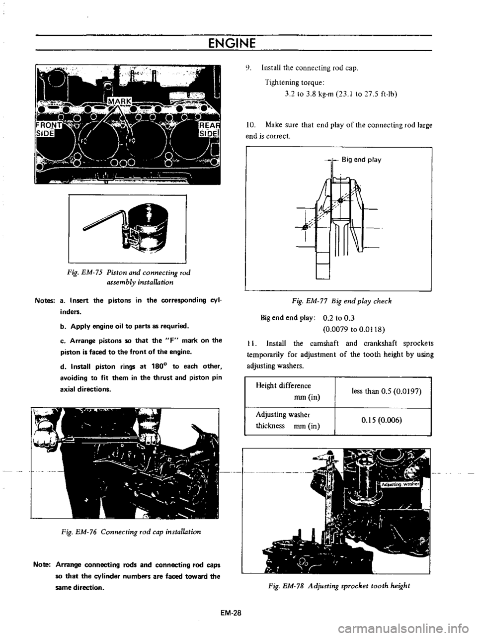
Fig
EM
75
Piston
and
connecting
rod
assembly
installation
Notes
8
I
nsert
the
pistons
in
the
corresponding
cyl
inders
b
Apply
engine
oil
to
parts
as
requried
c
Arrange
pistons
so
that
the
F
mark
on
the
piston
is
faced
to
the
front
of
the
engine
d
Install
piston
rings
at
180
to
each
other
avoiding
to
fit
them
in
the
thrust
and
piston
pin
axial
directions
Fig
EM
76
Connecting
rod
cap
installation
Note
Arrange
connecting
rods
and
connecting
rod
caps
so
that
the
cylinder
numbers
are
faced
toward
the
same
direction
EM
28
q
Install
the
connecting
rod
cap
Tightening
torque
32
to
3
8
kg
m
23
I
to
7
S
ft
lb
10
Make
sure
that
end
play
of
the
connecting
rod
large
end
is
correct
Big
end
play
j
I
Fig
EM
77
Big
end
play
check
Big
end
end
play
0
2
to
0
3
0
0079
to
0
0118
11
Install
the
camshaft
and
crankshaft
sprockets
temporarily
for
adjustment
of
the
tooth
height
by
using
adjusting
washers
Height
difference
mm
in
less
than
O
S
0
0197
Adjusting
washer
thickness
mm
in
O
IS
0
006
Fig
EM
78
Adjusting
sprocket
tooth
height
Page 469 of 513
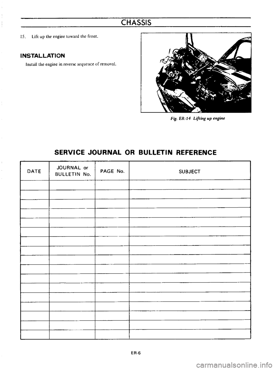
15
Lift
up
the
engine
toward
the
front
INSTALLATION
Install
the
engine
in
reverse
sequence
of
removal
CHASSIS
Fig
ER
14
Lifting
up
engine
SERVICE
JOURNAL
OR
BULLETIN
REFERENCE
DATE
JOURNAL
or
BULLETIN
No
PAGE
No
ER
6
SUBJECT
Page 494 of 513
TRANSMISSION
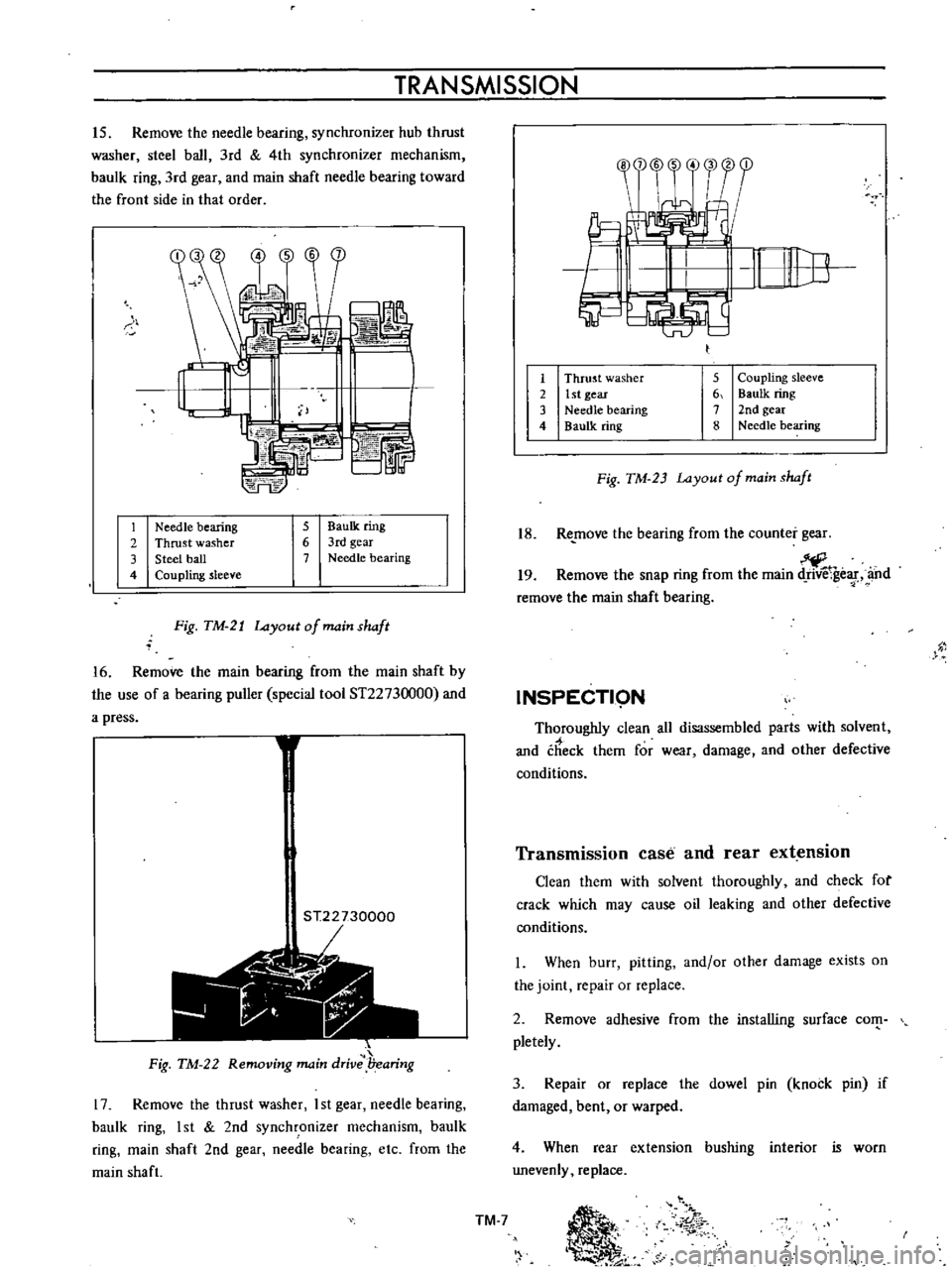
15
Remove
the
needle
bearing
synchronizer
hub
thrust
washer
steel
ball
3rd
4th
synchronizer
mechanism
baulk
ring
3rd
gear
and
main
shaft
needle
bearing
toward
the
front
side
in
that
order
S
b
L
74FE
r
1
Needle
bearing
2
Thrust
washer
3
Steel
ball
4
Coupling
sleeve
5
BauIk
ring
6
3rd
gear
7
Needle
bearing
Fig
TM
21
Layout
of
main
shaft
16
Remove
the
main
bearing
from
the
main
shaft
by
the
use
of
a
bearing
puller
special
tool
ST2273
000
and
a
press
1
ST22730000
r
1
t
Jii
Fig
TM
22
Removing
main
drive
l7earing
17
Remove
the
thrust
washer
I
st
gear
needle
bearing
baulk
ring
1st
2nd
synchronizer
mechanism
baulk
ring
main
shaft
2nd
gear
needle
bearing
etc
from
the
main
shaft
1
2
3
4
5
Coupling
sleeve
6
Baulk
ring
7
2nd
gear
8
Needle
bearing
Thrust
washer
1st
gear
Needle
bearing
Baulk
ring
Fig
TM
23
Layout
of
main
shaft
18
Re
move
the
bearing
from
the
counter
gear
19
Remove
the
snap
ring
from
the
main
ge
f
and
remove
the
main
shaft
bearing
INSPECTI9N
Thoroughly
clean
all
disassembled
parts
with
solvent
and
check
them
for
wear
damage
and
other
defective
conditions
Transmission
case
and
rear
extension
Clean
them
with
solvent
thoroughly
and
check
for
crack
which
may
cause
oil
leaking
and
other
defective
conditions
I
When
burr
pitting
and
or
other
damage
exists
on
the
joint
repair
or
replace
2
Remove
adhesive
from
the
installing
surface
com
pletely
3
Repair
or
replace
the
dowel
pin
knock
pin
if
damaged
bent
or
warped
4
When
rear
extension
bushing
interior
is
worn
unevenly
replace
TM
7
Ii
01
r
Page 503 of 513
CHASSIS
REINSTALLATION
Remount
the
transmission
in
reverse
sequence
of
dismounting
TRANSMISSION
GEAR
CONTROL
CONTENTS
DESCRIPTION
COLUMN
SHIFT
CONTROL
SYSTEM
Removal
TM
16
TM
17
TM
17
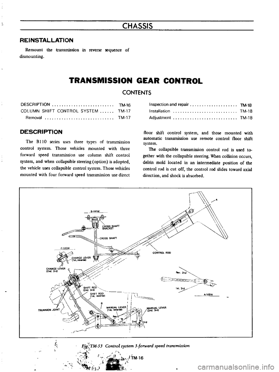
DESCRIPTION
The
B
10
series
uses
three
types
of
transmission
control
system
Those
vehicles
mounted
with
three
forward
speed
transmission
use
column
shift
control
system
and
when
collapsible
steering
option
is
adopted
the
vehicle
uses
collapsible
control
system
Those
vehicles
mounted
with
four
forward
speed
transmission
use
direct
B
VIEW
CROSS
SHAFT
BRACKET
CROSS
SHAfT
C
VIEW
HANGE
LEVER
l
rwIl
CHANGE
LEVER
C
2
3rdl
r
X
h
Inspection
and
repair
Installation
Adjustment
TM
18
TM
18
TM
18
floor
shift
control
system
and
those
mounted
with
automatic
transmission
use
remote
control
floor
shift
system
The
collapsible
transmission
control
rod
is
used
to
gether
with
the
collapsible
steering
When
collision
occurs
delrin
mold
located
in
an
intermediate
position
of
the
control
rod
is
cut
off
the
control
rod
slides
toward
axial
direction
and
shock
is
absorbed
c
0
CONTROL
ROD
r
A
v
t
c
t
IT
Ii
A
VIEW
MANUAL
LEVER
II
l
MANUAl
lEVER
11st
r
lW1
11nd3rd
IIooV
j
II
1
0SI
2nd
Jrd
I
I
j
tl
Control
system
3
forward
speed
transmission
Ffg
TM
53
t
f
Voo
1
ITM
16