Page 169 of 200

Attaching the windscreen wiper blade›Slide the windscreen wiper blade in the opposite direction to arrow 3 until it
locks into place. Check that the windscreen wiper blade is correctly attached.›
Fold the windscreen wiper arm back to the windscreen.
›
Turn on the ignition and press the lever in the direction of the arrow
» Fig. 189 .
The windscreen wiper arms move into the home position.
Replacing the rear window wiper blade
Fig. 191
Changing the rear window wiper blade
Read and observe
on page 166 first.
Removing the wiper blade
›
Lift the wiper arm » page 167 from the window in the direction of arrow
1
» Fig. 191.
›
Tilt the wiper blade to the stop in the same direction.
›
Grip the wiper arm and press securing latch
A
down in the direction of arrow
2
.
›
Remove the wiper blade in the direction of the arrow
3
.
Attaching the windscreen wiper blade
›
Slide the windscreen wiper blade in the opposite direction to arrow
3
until it
locks into place. Check that the windscreen wiper blade is correctly attached.
›
Fold the windscreen wiper arm back to the windscreen.
Fuses and light bulbs
Fuses
Introduction
Fig. 192
Blown fuse
This chapter contains information on the following subjects:
Fuses in the dashboard
168
Fuse arrangement in the dashboard
168
Fuses in the engine compartment
169
Fuse arrangement in the engine compartment
169
Individual electrical circuits are protected by fuses. A blown fuse is recognisa-
ble from the melted-through metal strip » Fig. 192.
WARNINGAlways read and observe the warnings before completing any work in the
engine compartment » page 142.
CAUTION
■
Replace the faulty fuse with a new one of the same amperage.■If a newly inserted fuse again blows after a short time, then seek assistance
from a specialist garage.■
“Do not repair” the fuses and do not replace them with stronger fuses -
There is a risk of fire and damage to another electrical system.
Note
■ We recommend always carrying replacement fuses in the vehicle.■There can be several power consuming devices for one fuse. Multiple fuses
may exist for a single power consuming device.167Fuses and light bulbs
Page 170 of 200

Fuses in the dashboardFig. 193
Distribution board cover.
Read and observe and on page 167 first.
The fuses are located on the left side of the dash panel behind a cover.
Replacing fuses
›
Remove the ignition key, turn off the lights and all electrical consumers.
›
Insert a screwdriver into the opening in the cover in the direction of the ar-
row » Fig. 193 .
›
Remove the cover of the fuse box and remove.
›
Remove the plastic clip from the holder in the fuse box cover in the dash
panel.
›
Use the clip to pull the fuse out, then insert a new fuse.
›
Re-insert the cover of the fuse box .
›
Replace the bracket at the original position.
Fuse arrangement in the dashboard
Fig. 194
Fuses
Read and observe and on page 167 first.No.Consumer1Heating of the gearbox vent (diesel engine)
Automatic gearbox2Towing hitch - left light3Trailer device - electrical outlet4Instrument cluster control lever under the steering wheel, camera5Air blower for heating, radiator fan, air conditioning system, Clima-
tronic6Rear window wiper7emergency call8Towing hitch - right light9Interior lighting, rear fog light10Rain sensor, light switch, diagnostic socket11Left side front headlight12Right side front headlight13Radio14Central control system, engine management system15Light switch16All-wheel drive17KESSY, steering lock18Diagnostic connector, engine control system, brake sensor, four-
wheel drive, START-STOP19ABS, ESP, switch for tyre air pressure control, parking aid, switch for
OFF ROAD mode, START STOP button20Airbag21Variable Service Interval - WIV, reversing lamps, dimmable mirrors,
pressure sensor, telephone preparation, air mass meter, headlamp
levelling and swivelling headlights22Instrument cluster, electromechanical power steering, databus23Central locking, boot lid24Electric windows - Rear25Rear window heater, auxiliary heating and ventilation26Power socket in the boot 168Do-it-yourself
Page 171 of 200

No.Consumer27Panoramic tilt / slide sunroof, electric operation of sun blinds28Fuel pump, injectors, AdBlue®
heating29Electric windows - front, outside mirror - Heating, fold-in function,
Adjusting the mirror surface3012 volt power outlet - front and rear31Headlight cleaning system32Heated front seats33Heating, air conditioning, Climatronic, remote control for auxiliary
heating34Car alarm, reserve horn35Automatic gearbox36Tow hitch
Fuses in the engine compartment
Fig. 195
Distribution board cover.
Read and observe and on page 167 first.
With some equipment, the battery cover must be opened before removing the
cover for the fuse box » page 148.
Replacing fuses
›
Turn the securing bracket
A
» Fig. 195 in direction of the arrow. The symbol
is displayed behind the catches. .
›
Remove the cover.
›
Replace the appropriate fuse.
›
Replace the cover on the fuse box and the safety clip
A
move against the
arrow. The symbol is displayed behind the catches .
CAUTIONThe cover of the fuse box in the engine compartment must always be used
correctly, otherwise water may penetrate into the fuse box – there is a risk of
damage to the vehicle!
Fuse arrangement in the engine compartment
Fig. 196
Fuses
Read and observe and on page 167 first.
No.Consumer1Not assigned2Automatic gearbox, AdBlue control system3Battery data module4ABS5Automatic gearbox6Not assigned7Power supply for terminal 15, starter8Radio, instrument cluster, telephone9Not assigned10Engine control system11Aux. heating and ventilation12Databus13Engine control system14Ignition15Lambda probe, fuel pump, glow plug system16Right headlight, right taillight17Horn 169Fuses and light bulbs
Page 172 of 200

No.Consumer18Music amplifier19Windscreen wipers20Control valve for fuel pressure, high pressure pump21Lambda probe22Clutch pedal switch, brake pedal switch23Coolant pump, loading pressure control valve, switchover valve for
radiator, fuel pump24Active charcoal filter, exhaust gas recirculation valve, radiator fan25ABS26Left front headlight, left taillight27Glow plug system28Windscreen heater29Power to the internal fuse carrier (fuses no. 24,27,31,32), electrically
adjustable seats30Terminal X a)a)
In order not to drain the battery unnecessarily when starting the engine, the electrical components of
this terminal are automatically switched off.
Bulbs
Introduction
This chapter contains information on the following subjects:
Bulb arrangement in the front headlights
171
Changing bulbs for low and main beam (Halogen headlights)
171
Remove protective guard for foglights
171
Protective grille for removing fog lights- plug for Park Assist sensor
172
Changing light bulbs for fog lights
172
Changing the bulb for the licence plate light
173
Removing/installing taillights
173
Replacing the bulbs in the taillight assembly
174
We recommend having bulbs replaced by a specialist garage or seeking other
expert help in the event of any uncertainties.
▶ Switch off the ignition and all of the lights before replacing a bulb.
▶ Faulty bulbs must only be replaced with the same type of bulbs. The designa-
tion is located on the light socket or the glass bulb.
We recommend having the headlight settings checked by a specialist garage after replacing a bulb in the low, high or fog beam.
In the case of failure of a Xenon gas discharge bulb or an LED diode, visit a
specialist garage.WARNING■ Always read and observe the warnings before completing any work in the
engine compartment » page 142.■
Accidents can be caused if the road in front of the vehicle is not suffi-
ciently illuminated and the vehicle cannot or can only be seen with difficul-
ty by other road users.
■
Bulbs H7 and H4 are pressurised and may burst when changed - there is a
risk of injury. We therefore recommended wearing gloves and safety
glasses when changing a bulb.
■
Do not carry out any work on the Xenon gas discharge lamps - risk of
death!
CAUTION
Do not take hold of the glass bulb with naked fingers (even the smallest
amount of dirt reduces the working life of the light bulb). Use a clean cloth,
napkin, or similar.
Note
■ This Owner's Manual only describes the replacement of bulbs where it is pos-
sible to replace the bulbs on your own without any complications arising. Other
bulbs must be replaced by a specialist garage.■
We recommend that a box of replacement bulbs always be carried in the ve-
hicle.
170Do-it-yourself
Page 173 of 200

Bulb arrangement in the front headlightsFig. 197
Left headlight
Read and observe and on page 170 first.
Bulb arrangement » Fig. 197
Low beam with halogen bulb or Xenon gas discharge bulb
Main beam
Changing bulbs for low and main beam (Halogen headlights)
Fig. 198
Replacing the bulb for low beam and main beam
Read and observe
and on page 170 first.
›
Turn the respective protective cap » Fig. 197 on page 171 counter-clockwise
and remove.
When removing the cap, make sure that this does not fall into the engine com-
partment.
›
Disconnect the relevant connector with the light bulb in the direction of ar-
row
1
» Fig. 198 .
AB›Remove the connector to the bulb in the direction of arrow 2.›Remove the connector.›
Insert the connector with the new bulb so that the fixing lug
A
fits on the
bulb » Fig. 198 into the recess on the reflector.
›
Insert the respective protective cap » Fig. 197 on page 171 and rotate it clock-
wise until it stops.
Note
We recommend you have the bulb replacement performed by a specialist ga-
rage.
Remove protective guard for foglights
Fig. 199
Guard: Version 1/version 2
Read and observe
and on page 170 first.
›
Undo the protective grille in the direction of the arrow » Fig. 199 using the
clamp for removing the wheel trims.
›
Remove the protective grille.
171Fuses and light bulbs
Page 174 of 200

Protective grille for removing fog lights- plug for Park AssistsensorFig. 200
Guard: Version 1/version 2
Fig. 201
Remove the plug
Read and observe
and on page 170 first.
›
Remove the plastic cover for the guard in the arrow direction » Fig. 200 using
the bow to pull the full wheel covers.
›
Remove the remaining part of the grille.
›
Pull the latch out of the connector in the direction of arrow
1
» Fig. 201 .
›
Undo the latch on the connector in the direction of arrow
2
.
›
Remove the key in the direction of the arrow
3
.
Insertion of the ashtray takes place in reverse order.
Changing light bulbs for fog lightsFig. 202
Remove the number plate light / replace the bulb
Read and observe
and on page 170 first.
First remove the grille for the fog lights and before changing bulbs » Fig. 199
on page 171 and / or » Fig. 200 on page 172 .
Removing the headlight
›
Unscrew the screws
A
» Fig. 202 with the screwdriver from the tool kit.
›
Remove the headlight in the direction of arrow
1
.
›
Remove the headlight in the direction of arrow
2
.
Replacing the light bulb
›
Pull the plug on the lamp base.
›
Turn the socket with the bulb to the stop in the direction of the arrow
3
» Fig. 202 .
›
Insert the new bulb into the headlight and turn counter to the direction of
arrow
3
as far as the stop.
›
Attach the connector on the lamp base.
Refit the headlight and grille
›
Replace the fog light by inserting it in the opposite direction of the arrow
2
» Fig. 202 and tighten.
›
Attach the connector on guard carefully » Fig. 201 on page 172 1)
.
›
Insert the protective grille and press it in.
›
Replace the plastic cover and press into the guard » Fig. 200 on page 172 1 )
.
The protective grille must engage firmly.
1)
Applies to vehicles with parking assistance system.
172Do-it-yourself
Page 175 of 200

CAUTIONFor vehicles with parking assistance, we recommend that after changing the
light bulb in the fog lights, the system is checked by a specialist.
Changing the bulb for the licence plate light
Fig. 203
Remove / replace the bulb for the number plate light
Read and observe
and on page 170 first.
›
Open the boot lid.
›
Push the light in the direction of arrow
1
» Fig. 203 until it comes loose.
›
Swivel out the lamp in the direction of the arrow
2
and remove it.
›
Remove the faulty bulb from the holder in the direction of the arrow
3
.
›
Insert a new bulb into the holder.
›
Reinsert the lamp in the opposite direction to the arrow
1
.
›
Push on the light until the spring clicks into place.
›
Close the boot lid.
Removing/installing taillightsFig. 204
Remove light / pull out connector
Read and observe
and on page 170 first.
Removing
›
Open the boot lid.
›
Use the screwdriver from the tool kit to unscrew the lamp » Fig. 204.
›
Grasp the light and carefully remove with shaky movements in the direction
of arrow
1
» Fig. 204 .
›
Disconnect the plug connection by pressing the catches in direction of arrow
2
and by pulling them in direction of arrow
3
.
Fitting
›
Insert the connector into the light and lock it securely.
›
Insert the light into the mounts in the body » Fig. 204.
›
Carefully press the light into the body so that the bolts
1
» Fig. 205 on
page 174 or » Fig. 206 on page 174 on the light engage into the mounts on
the body »
.
›
Screw the light with the screws into place » Fig. 204.
›
Close the boot lid.
CAUTION
Ensure that the vehicle paintwork and the tail lamp are not damaged when re-
moving and installing the tail lamp.173Fuses and light bulbs
Page 176 of 200

Replacing the bulbs in the taillight assemblyFig. 205
Inner part of the light: Ground light
Fig. 206
Inner part of the light: Light with LED diodes
Read and observe
and on page 170 first.
Ground light
›
With the spanner from the vehicle tools unscrew the securing screw
A
» Fig. 205 .
›
Unlock the bulb holder using the locking latches in the areas » Fig. 205
marked with arrows and remove the bulb holder from the light.
›
Turn the respective bulb
B
until it stops counter-clockwise and remove it
from the bulb holder.
›
Insert a new bulb
B
into the holder and turn in a clockwise direction to the
stop.
›
Pull bulb
C
out of the socket and insert a new bulb.
›
Insert the lamp holder in the lamp and screw in the locking screw
A
» Fig. 205 .
Light with LED diodes›Unlock the bulb holder using the locking latches in the areas » Fig. 206
marked with arrows and remove the bulb holder from the light.›
Turn the respective light bulb » Fig. 206 until it stops counter-clockwise and
remove it from the bulb holder.
›
Insert a new bulb into the holder and turn in a clockwise direction to the
stop.
›
Insert the lamp holder in the lamp until it is secure.
174Do-it-yourself
 1
1 2
2 3
3 4
4 5
5 6
6 7
7 8
8 9
9 10
10 11
11 12
12 13
13 14
14 15
15 16
16 17
17 18
18 19
19 20
20 21
21 22
22 23
23 24
24 25
25 26
26 27
27 28
28 29
29 30
30 31
31 32
32 33
33 34
34 35
35 36
36 37
37 38
38 39
39 40
40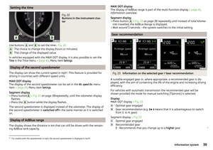 41
41 42
42 43
43 44
44 45
45 46
46 47
47 48
48 49
49 50
50 51
51 52
52 53
53 54
54 55
55 56
56 57
57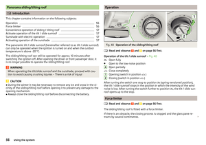 58
58 59
59 60
60 61
61 62
62 63
63 64
64 65
65 66
66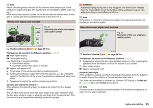 67
67 68
68 69
69 70
70 71
71 72
72 73
73 74
74 75
75 76
76 77
77 78
78 79
79 80
80 81
81 82
82 83
83 84
84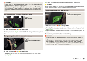 85
85 86
86 87
87 88
88 89
89 90
90 91
91 92
92 93
93 94
94 95
95 96
96 97
97 98
98 99
99 100
100 101
101 102
102 103
103 104
104 105
105 106
106 107
107 108
108 109
109 110
110 111
111 112
112 113
113 114
114 115
115 116
116 117
117 118
118 119
119 120
120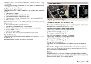 121
121 122
122 123
123 124
124 125
125 126
126 127
127 128
128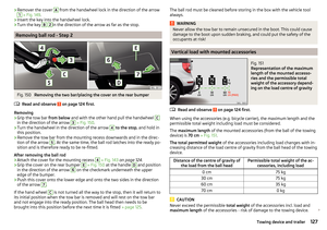 129
129 130
130 131
131 132
132 133
133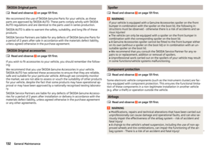 134
134 135
135 136
136 137
137 138
138 139
139 140
140 141
141 142
142 143
143 144
144 145
145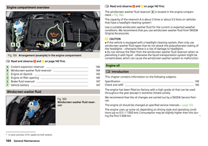 146
146 147
147 148
148 149
149 150
150 151
151 152
152 153
153 154
154 155
155 156
156 157
157 158
158 159
159 160
160 161
161 162
162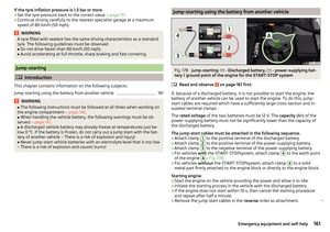 163
163 164
164 165
165 166
166 167
167 168
168 169
169 170
170 171
171 172
172 173
173 174
174 175
175 176
176 177
177 178
178 179
179 180
180 181
181 182
182 183
183 184
184 185
185 186
186 187
187 188
188 189
189 190
190 191
191 192
192 193
193 194
194 195
195 196
196 197
197 198
198 199
199