Page 121 of 200

▶The display shows instructions and information before the start and during
the parking.
▶ Based on the calculated road surface, the front wheels will be automatically
rotated during the parking.
Conditions for the system function
The system can look for a parking space only if the following basic conditions
are met.
The system is activated.
The vehicle is travelling at less than 40 km/h.
The vehicle is travelling at less than 20 km/h.
The distance to a number of parked vehicles is approximately 0.5-1.5 m.
TCS is activated » page 111.
The system can only carry out the parking procedure if the following basic con- ditions are met.
The vehicle is travelling at less than 7 km/h.
The parking procedure takes less than 6 minutes.
There is no driver intervention in the automatic steering operation.
TCS is activated » page 111.
The TCS does not engage.
No trailer or other accessory is connected to the trailer socket.
Activation/deactivation
The system can be activated/deactivated by pressing the button
» Fig. 139
on page 119 -
.
When the system is activated, the symbol illuminates.Parking space searchFig. 139
System button / display
Read and observe
and on page 118 first.
The system searches for a parking space in a number of parallel and transverse
parked vehicles on the passenger or driver's side.
Search for a parking space parallel to the roadway
›
Slowly drive past a row of parallel parked vehicles.
›
Press the button once
» Fig. 139 -
.
The display shows the following - .
Search for a parking space traverse to the roadway
›
Slowly drive past a row of traverse parked vehicles.
›
Press the button twice
» Fig. 139 -
.
The display shows the following -
Change sides for the parking
The system will automatically search for a parking space on the passenger
side.
Activate the turn signal on the driver's side if you wish to look fro a parking
space on this side of the road. The display changes and the system searches
for a parking space on the driver's side.
Note
If the symbol (km / h) is shown in the display while you are looking for a
parking space, the vehicle speed should be reduced below 40 km / hr (parallel parking) or below 20 km / hr (Transverse parking).119Assist systems
Page 122 of 200

ParkingFig. 140
Display
Read and observe
and on page 118 first.
The system supports the driver when reverse parking in the parking space
found in a number of traverse and parallel parked vehicles.
Display » Fig. 140
Parking space recognised with the information to drive on
Parking space recognised with the information to reverse
Note to drive on to the parking space
Note to reverse to the parking space
Parking manoeuvre
The parking space found is shown in the display » Fig. 140 -
.
›
Continue driving forwards until
appears in the display.
›
Stop and ensure that the vehicle does not continue to move forward until
the parking procedure starts.
›
Select reverse gear or move the selector lever into position R.
›
As soon as the following message is shown in the display:
Steering int. active.Monitor area around veh.!
, let go of the steering wheel. The steering will be taken
over by the system.
›
Observe the direct vicinity of the vehicle and reverse carefully.
If necessary, the parking procedure can be continued with further steps.
›
If the arrow in the information display is flashing to the front , engage
1 gear or move the selector lever into the position D.
The display shows the icon (brake pedal).
›Depress the brake pedal and wait until the steering wheel automatically ro-
tates into the required position, the symbol goes out.›
Carefully drive forwards.
›
If the backwards arrow is flashing in the display -
, select reverse gear
again or move the selector lever into position R.
The display shows the
icon (brake pedal).
›
Depress the brake pedal and wait until the steering wheel automatically ro-
tates into the required position, the symbol
goes out.
›
Carefully move backwards.
You can repeat these steps several times in succession.
As soon as the parking procedure is complete, an audible signal sounds and the following message appears in the display.
Departing from a parallel parking space
Read and observe
and on page 118 first.
The system supports the driver when leaving a parking space of a parallel
parking space.
Leaving a parking space process
›
Press the symbol key
» Fig. 139 on page 119 .
The following message is displayed:
PARK ASSIST Turn on turn signal and select reversegear.›
Activate the turn signal for side of the vehicle where the parking space is out
of which you wish to manoeuvre.
›
Select reverse gear or move the selector lever into position R.
The further procedure is analogous to that for reverse parking.
›
Follow the system instructions shown in the display.
As soon as the parking procedure is complete, an audible signal sounds and
the following message appears in the display.
If the parking space is too small, it is not possible to use the system to leave
the parking space. A corresponding message is shown in the information clus-
ter display.
120Driving
Page 123 of 200

Automatic brake assistRead and observe
and on page 118 first.
Automatic brake assist when speeding
If a velocity of 7 km / h is exceeded during the parking manoeuvre for the first
time, the speed will be automatically reduced by the system to less than 7 km /
h. This prevents the parking manoeuvre from aborting.
Automatic emergency braking
If the system detects a risk of collision during parking, automatic emergency
braking takes place to prevent a collision.
The parking is terminated by the emergency braking.
CAUTION
The automatic emergency braking is not triggered by the system when the
parking process stops due to the speed of 7 km / hr being exceeded!
Malfunctions
Read and observe
and on page 118 first.
If, for some unknown reason, the system is not available, an appropriate mes-
sage appears in the display of the instrument cluster.
System unavailable
If the system is not available because the vehicle has a fault, a message ap-
pears concerning the unavailability. Seek help from a specialist garage.
System fault
In the case of a system fault, an error message appears. Seek help from a spe-
cialist garage.
Cruise Control System
Introduction
This chapter contains information on the following subjects:
Operation
121
Operation description
122The Cruise Control System (CCS) maintains a set speed without you having to
actuate the accelerator pedal. The state where the CCS maintains the speed is
referred to hereinafter as the control.WARNINGThe general information relating to the use of assistance systems must be
observed » page 110, in section General information .
Operation
Read and observe
on page 121 first.
Basic requirements for start of control The CCS is activated.
On vehicles with a manual transmission , the second gear or higher is en-
gaged.
On vehicles with an automatic transmission , the selector lever is in the
D/S position or in the Tiptronic position.
The current speed is higher than 20 km/h.
This, however, is only possible to the extent permitted by the engine output
and braking power of the vehicle.
WARNINGIf the engine output or engine braking effect is insufficient to maintain the
set speed, the driver must assume control of the accelerator and brake
pedals!121Assist systems
Page 124 of 200
 I")
Operation descriptionFig. 141
Cruise control system controls
Read and observe on page 121 first.
Overview of the CCS controls » Fig. 141AActivate CCS (control deactivated) Interrupt control (sprung position) Deactivate CCS (delete set speed)BTake control again a)
/ Increase speedCLaunch control / reduce speeda)
If no speed is set the current speed is adopted.
Once the controls are activated, the CCS maintains the vehicle at the set
speed; the warning light lights up in the instrument cluster.
After the interruption in control, the stored speed can be resumed by pressing
the
B
button.
Controls are automatically interrupted if any of the following occur.
▶ By pressing the brake or clutch pedal.
▶ When one of the brake assist systems (e.g. ESC) intervenes.
▶ Through an airbag deployment.
WARNING■ Always deactivate the cruise control system after use to prevent the sys-
tem being switched on unintentionally.■
Control may only be resumed if the set speed is not too high for the cur-
rent traffic conditions.
NoteDuring control, speed can be increased by pressing the accelerator pedal. Re-
leasing the accelerator pedal will cause the speed to drop again to the set
speed.
Fatigue detection
The fatigue detection system (hereinafter referred to as system) recommends
the driver takes a break from driving when driver fatigue can be detected due
to the driver's steering behaviour.
From the starting of the journey, the system evaluates the steering behaviour
at speeds 65-200 km/h. If, while driving, there have been changes in the steer-
ing behaviours that are evaluated by the system as indicating possible fatigue,
a break recommendation is issued.
Conditions under which a break from driving is detected by the system ▶ The vehicle is stopped and the ignition switched off.
▶ The vehicle is stopped, the seat belt removed and the driver's door opened.
▶ The vehicle is stopped for more than 15 minutes.
If none of these conditions are met or if the driving style is not changed, the
system recommends a driving break again after 15 minutes.
The system can be activated / deactivated in MAXI DOT display » page 43.
Pause recommendation
The icon appears and the following message for a few seconds in the display
of the instrument cluster and a message about the detected fatigue. An au-
dible signal is also emitted.
WARNING■ The general information relating to the use of assistance systems must
be observed » page 110, in section General information .■
For the driving ability is always the driver's responsibility. Never drive if
you feel tired.
■
The system may not detect all cases where a break is needed.
■
Therefore, take regular, sufficient breaks during long trips.
■
There will be no system warning during the so-called micro-sleep.
122Driving
Page 125 of 200
.■
The sys")
Note■In some situations, the system may evaluate the driving incorrectly and thus
mistakenly recommend a break (e.g. sporty driving, adverse weather condi-
tions or poor road conditions).■
The system is designed primarily for use on motorways.
Tyre pressure monitoring
Fig. 142
Key for storing the pressure val-
ues
The tyre pressure monitoring function (hereinafter referred to as the system)
monitors the tyre pressure while driving.
If the tyre inflation pressure changes, the warning light
lights up in the in-
strument cluster and an audible signal is heard » page 36,
Tyre pressure .
The system can only function properly if the tyres have the prescribed inflation
pressure and these pressure values are stored in the system.
Procedure for storing the tyre pressure values
›
Inflate all the tyres to the specified pressure.
›
Switch on the ignition.
›
Press the button
» Fig. 142 and hold.
The warning light
lights up in the instrument cluster.
An acoustic signal and the control indicator provide information about the
storage of the tyre pressure values.
›
Release the button
.
Always save the tyre pressure values in the system if one of the following
events occurs.
▶ Change of tyre inflation pressure.
▶ Change one or more wheels.
▶ Change in position of a wheel on the vehicle.
▶ Illumination of the warning light
in the instrument cluster.
WARNING■
The general information relating to the use of assistance systems must
be observed » page 110, in section General information .■
Having the correct tyre inflation pressure is always the driver's responsi-
bility. Tyre pressure should be checked regularly » page 151.
■
The system cannot warn in case of very rapid tyre inflation pressure loss,
e.g. in case of sudden tyre damage.
■
Before storing the pressures, the tyres must be inflated to the specified
inflation pressure » page 151. If the wrong pressure valuesare stored, the
system may not issue any warnings, even if the tyre pressure is too low.
CAUTION
Save the tyre pressure values every 10,000 km or 1x annually to ensure correct
system functioning.123Assist systems
Page 126 of 200

Towing device and trailer
Hitch
Introduction
This chapter contains information on the following subjects:
Description
124
Setting the ready position
125
Check the setting of the standby position
125
Assemble the ball rod
125
Check proper mounting
126
Removing ball rod - Step 1
126
Removing ball rod - Step 2
127
Vertical load with mounted accessories
127
The maximum trailer nose weight when towing a trailer is 80 kg, for vehicles
with four-wheel drive and the 2.0 l / 103 kW TDI CR or 2.0 l / 110 kW TDI CR
engine, it is 85 kg. Other information (e.g. on the nameplate of the trailer de-
vice) provide only about the test values of the device information.
WARNING■ Check that the tow bar is seated correctly and is secured in the mounting
recess before the start of every journey.■
When the ball rod is not used and properly secured in the receiving shaft,
this could be damaged or incomplete and must not be used -There is a risk
of an accident.
■
Do not modify or adapt the towing device in any way.
■
Keep the mounting recess of the towing equipment clean at all times.
Such dirt prevents the ball head from being attached securely.
DescriptionFig. 143
Carrier for the towing device/tow bar
Read and observe
on page 124 first.
The ball rod is detachable and is located in the stowage compartment for the
spare / emergency wheel.
Support for the towing device and tow bar » Fig. 143
13-pin power socket
Mounting recess
Safety eyelet
Cover for the mounting recess
Dust cap
Locking ball
Green marking on the handwheel
Handwheel
Key
Lock cap
Red marking on the handwheel
Green box on the tow bar
Tow ball
12345678910111213124Driving
Page 127 of 200

Setting the ready positionFig. 144
Lock unlock / pull out hand wheel and turn
Read and observe
on page 124 first.
The tow bar must be set to the ready position prior to installation » page 125,
Check the setting of the standby position .
›
Grip the tow bar below the protective cap.
›
Remove the cap from the lock.
›
Insert the key into the hand wheel lock.
›
Turn the key
A
in direction of the arrow
1
to the stop » Fig. 144.
›
Pull the handwheel
B
in the direction of the arrow
2
and drag in the direc-
tion of the arrow
3
to the stop. The hand wheel
B
remains locked in this
position.
Check the setting of the standby position
Fig. 145
Ready position
Read and observe on page 124 first.
Correctly adjusted standby position » Fig. 145
The locking balls
A
can be pushed fully into the tow bar.
The red marking
B
on the hand wheel is located in the green box on the
tow bar.
The key
C
is in the unlocked position and cannot be removed.
There is a clear gap of approx. 5 mm
D
between the hand wheel and the
tow bar.
When in the ready position, the key cannot be removed from the lock. The ball
bar is thus set ready for installation.
Assemble the ball rod
Fig. 146
Removing the cap on the rear bumper/inserting the tow bar
125Towing device and trailer
Page 128 of 200

Fig. 147
Locking the lock and removing the key/replacing the lock cap
Read and observe
on page 124 first.
›
Grip the cap on the rear bumper
B
» Fig. 146 at the handle
A
, release in the
direction of the arrow
1
and remove in the direction of the arrow
2
.
›
Remove the cover for the mounting recess
4
» Fig. 143 on page 124 in a
downwards direction.
›
Adjust the ball rod to the ready position » page 125.
›
Grasp the ball rod from underneath » Fig. 146 and install into the receiving
shaft in the direction of arrow
3
until it stops. The ball rod must audibly
snap into place » .
The handwheel
C
» Fig. 146 returns automatically and rests on the tow bar
» .
›
Lock the handwheel lock by turning the key
D
» Fig. 147 to the left in the
direction of the arrow
4
to the stop, and remove the key in the direction of
the arrow
5
.
›
Put the cap
E
onto the handwheel lock in the direction of the arrow
6
.
›
Check that the tow bar is securely attached » page 126.
WARNING■
When attaching the tow bar, do not hold the handwheel by hand - risk of
injuring fingers!■
Carefully remove the cap for the mounting recess - there is a risk of hand
injury!
Check proper mountingFig. 148
Correctly secured ball head
Read and observe on page 124 first.
Correctly secured ball rod » Fig. 148
The tow bar does not come out of the mounting recess even after heavy
“shaking”.
The green marking
A
on the handwheel is located in the green box on the
tow bar.
The steering wheel is tight against the ball rod.
The key is removed and the cap
C
is attached to the lock.
Removing ball rod - Step 1
Fig. 149
Removing the lock cover/releasing the lock
Read and observe
on page 124 first.
No trailer or other accessory is connected to the ball rod. We recommend put-
ting the protective cover onto the ball head before removing the ball rod.
126Driving
 1
1 2
2 3
3 4
4 5
5 6
6 7
7 8
8 9
9 10
10 11
11 12
12 13
13 14
14 15
15 16
16 17
17 18
18 19
19 20
20 21
21 22
22 23
23 24
24 25
25 26
26 27
27 28
28 29
29 30
30 31
31 32
32 33
33 34
34 35
35 36
36 37
37 38
38 39
39 40
40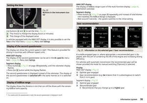 41
41 42
42 43
43 44
44 45
45 46
46 47
47 48
48 49
49 50
50 51
51 52
52 53
53 54
54 55
55 56
56 57
57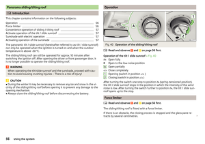 58
58 59
59 60
60 61
61 62
62 63
63 64
64 65
65 66
66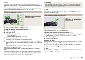 67
67 68
68 69
69 70
70 71
71 72
72 73
73 74
74 75
75 76
76 77
77 78
78 79
79 80
80 81
81 82
82 83
83 84
84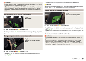 85
85 86
86 87
87 88
88 89
89 90
90 91
91 92
92 93
93 94
94 95
95 96
96 97
97 98
98 99
99 100
100 101
101 102
102 103
103 104
104 105
105 106
106 107
107 108
108 109
109 110
110 111
111 112
112 113
113 114
114 115
115 116
116 117
117 118
118 119
119 120
120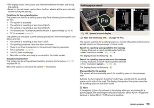 121
121 122
122 123
123 124
124 125
125 126
126 127
127 128
128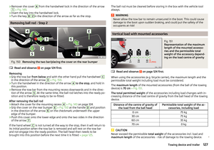 129
129 130
130 131
131 132
132 133
133 134
134 135
135 136
136 137
137 138
138 139
139 140
140 141
141 142
142 143
143 144
144 145
145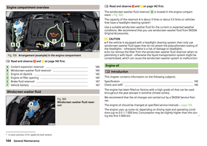 146
146 147
147 148
148 149
149 150
150 151
151 152
152 153
153 154
154 155
155 156
156 157
157 158
158 159
159 160
160 161
161 162
162 163
163 164
164 165
165 166
166 167
167 168
168 169
169 170
170 171
171 172
172 173
173 174
174 175
175 176
176 177
177 178
178 179
179 180
180 181
181 182
182 183
183 184
184 185
185 186
186 187
187 188
188 189
189 190
190 191
191 192
192 193
193 194
194 195
195 196
196 197
197 198
198 199
199