Page 25 of 200

Child safety and the side airbagFig. 13
Incorrect seated position of a
child who is not properly secured
– risk from the side airbag/Child
properly protected by safety seat
Read and observe on page 21 first.
The child must not be positioned in the deployment area of the side airbag
» Fig. 13 -
.
There must be sufficient room between the child and the deployment area of
the side airbag that the airbag can provide as much protection as possible
» Fig. 13 –
.
Classification of child seats
Read and observe
on page 21 first.
Classification of child seats according to the ECE-R 44 standard.
GroupWeight of the child0up to 10 kg0up to 13 kg19-18 kg215-25 kg322-36 kg
Use of child safety seats which are secured using a seat belt
Never use a rear-facing child seat on the front passenger seat if the front passenger airbag is activated. This child safety seat is positioned in the deployment
area of the front passenger airbag. The airbag may cause the child severe, or even fatal injuries, in the event of it being deployed.
Read and observe
on page 21 first.
Overview of the usability of child seats fastened with a seat belt on each of the seats in accordance with the ECE-R 16 standard.GroupFront passenger seatRear seatsExternalRear seat Centre0
up to 10 kgUUU0
up to 13 kgUUU1
9-18 kgUUUGroupFront passenger seatRear seatsExternalRear seat Centre2
15-25 kgUUU a)3
22-36 kgUUU a)a)
If the middle rear seat is not provided with a headrest, then a child seat of Group 2 or 3 is only to be used
if this has its own built-in headrest. If the child seat of Group 2 or 3 does not have its own built-in head-
rest, the child seat must be attached to the outer rear seat.
“Universal” child seat category - a child seat designed to be attached to
the seat using the seat belt.
U23Transporting children safely
Page 26 of 200

Fastening systems
Introduction
This chapter contains information on the following subjects:
attachment points of the
system
24
Use of child safety seats with the
system
24
Attachment points of the
system
25
attachment points of the system
Fig. 14
Labels of the system
is a system for securing child seats quickly and safely.
There are two fixing eyes between the seat backrest and the seat cushion of
the front passenger seat for fixing a child seat with the
system.
On the rear outside seats, the fixing eyes are located below the upholstery.
The places are marked with labels with the
logo » Fig. 14 .WARNING■
Always refer to the instructions of the manufacturer of the child seat
when installing and removing a child seat with the system.■
Never attach other child seats, belts or objects to the attachment points
intended for the installation of a child seat with the
system – risk of
death!
Note
■ A child seat fitted with the system can only be mounted in a vehicle fit-
ted with a system if the child seat has been approved for this type of ve-
hicle. Further information is available from a ŠKODA Partner.■
Child seats with the
system can be purchased from ŠKODA Original Ac-
cessories.
Use of child safety seats with the system
Never use a rear-facing child seat on the front passenger seat if the front passenger airbag is activated. This child safety seat is positioned in the deployment
area of the front passenger airbag. The airbag may cause the child severe, or even fatal injuries, in the event of it being deployed.Overview of the use-ability of the child seats fastened with the system on each of the seats in accordance with the ECE-R 16 standard.GroupSize class of
the child seat a)Front passenger seat
b)Outer rear seatsRear seat middle0
up to 10 kgEXIL-SUX0
up to 13 kgE
XIL-SUX
DC 24Safety
Page 27 of 200
Front passenger seat
b)Outer rear seatsRear seat middle
1
9-18 kg
D
XIL-SU IUFX
CBB1A2
15-25 kg-XIL-SUX3
22-36 kg-XIL-SUXa)
The size category is shown on the label")
GroupSize class of
the child seat a)Front passenger seat
b)Outer rear seatsRear seat middle
1
9-18 kg
D
XIL-SU IUFX
CBB1A2
15-25 kg-XIL-SUX3
22-36 kg-XIL-SUXa)
The size category is shown on the label attached to the child seat.
b)
If the front passenger seat is fitted with system attachment points, it is suitable for the installation of an
child seat with “Semi-Universal” approval.
IL-SUThe seat is suitable for the use of approved child seats in
in the “Semi-Universal”category. The “Semi-Universal” category means that the child seat
with the
system is approved for your vehicle. Observe the list of vehicles that comes with the child seat.IUFThe seat is suitable for the installation of a child seat with “Universal” approval and attachment with the system belt.XThe seat is not fitted with system attachment points.Attachment points of the systemFig. 15
Attachment points of the
-system
is a fastening system, which restricts the movement of the upper part
of the child seat.
The locking eyes
A
for attaching the belt of a child seat with the
sys-
tem are located on the rear side of the outer rear seat backrests » Fig. 15.
WARNING■
Always refer to the instructions from the manufacturer of the child seat
when installing and removing a child seat with the system.■
Only use child seats with the
system on the seats with the at-
tachment points.
■
Only ever attach one belt from the child seat to a locking eye.
25Transporting children safely
Page 28 of 200
Fig. 16
Cockpit example for LHD models
26Using the system
Page 29 of 200
:
▶ Direction and high beam")
Using the system
Cockpit
OverviewDoor opening lever
50
Electric exterior mirror adjustment
67
Air outlet vents
96
Ticket holder
75
Operating lever (depending on equipment):
▶ Direction and high beam
59
▶Speed regulating system
121
Steering wheel with horn / with driver's front airbag
16
Buttons for operating the information system
38
Instrument cluster
28
Operating lever:
▶ Windscreen wipers and washers
64
▶Information system
38
Warning light for the front passenger airbag
20
Button for hazard warning light system
61
Storage compartment
76
Interior rear-view mirror
66
Depending on specification:
▶ Radio
▶ Infotainment
Storage compartment on the front passenger side
82
Front passenger airbag
16
Electric window in the front passenger door
54
Electric windows
54
Storage compartment
76
Light switch
58
Bonnet release lever
143
Regulator for instrument lighting and regulator for headlight
beam range adjustment
29, 58
Steering wheel locking lever
111234567891011121314151617181920212223Depending on equipment fitted:
▶ Ignition lock101
▶Starter button
101
Bar with keys depending on the equipment fitted:
▶ START STOP
102
▶
Traction control TCS
111
▶
Electronic Stability Control ESC
110
▶
Parking aid
114
▶
OFF ROAD-mode
112
▶
Tyre pressure control indicator
123
▶
Park Assist
118
Handbrake lever
104
Central locking system
49
Depending on equipment fitted:
▶ 12-Volt power socket
79
▶Cigarette lighter
78
Depending on equipment fitted:
▶ Gearshift lever (manual gearbox)
105
▶Selector lever (automatic gearbox)
106
Storage compartment
76
Controls for heating / air conditioning
93
Key switch for switching off the front passenger airbag (in front
passenger storage compartment)
20
Note
The layout of the controls on right-hand drive vehicles differs partially from
that shown in this layout » Fig. 16.24252627282930313227Cockpit
Page 30 of 200

Instruments and Indicator Lights
Instrument cluster
Introduction
Fig. 17
Instrument cluster
This chapter contains information on the following subjects:
Rev counter
28
Coolant temperature gauge
29
Fuel gauge
29
Lighting of the instrument cluster
29
Auto Check Control
30
Engine revolutions counter » page 28
▶ with warning lights » page 31
Speedometer
▶ with warning lights » page 31
Operation key:
▶ Setting the time » page 39
▶ Switching the display for the second speedometer on/off 1)
» page 39
123▶
Displaying the distance and days until the next service interval 1)
» page 44
▶ Show AdBlue range 1)
» page 39
Coolant temperature gauge » page 29
Display » page 38
Fuel gauge » page 29
Operation key: ▶ Reset counter for distance travelled (trip) » page 38
▶ Setting the time
▶ Enable / disable the mode selected using the3
button
Rev counter
The tachometer
1
» Fig. 17 on page 28 shows the actual engine speed per mi-
nute.
The beginning of the tachometer red scale range indicates the maximum per-
mitted speed for an engine that has been driven-in and has reached operating
temperature.
You should shift into the next highest gear before the red scale of the revolu-
tion counter is reached, or select mode D / S on the automatic gearbox.
The gear recommendation is important to note in order to maintain the opti-
mum engine speed » page 39.
CAUTION
The rev counter pointer may only move into the red area for a short time - oth-
erwise there is a risk of engine damage!45671)
Applies to vehicles with a segment display.
28Using the system
Page 31 of 200

Coolant temperature gaugeFig. 18
Coolant temperature gauge
The display » Fig. 18 only works if the ignition is switched on.
Cold range - the pointer is in the range
A
, the engine has not yet reached its
operating temperature. Avoid high speeds and high engine loads.
Operating range - the pointer is in the range
B
.
High temperature range - the pointer is in the range
C
. The coolant tempera-
ture is too high. The warning light » page 32
illuminates in the instrument
cluster .
Fuel gauge
Fig. 19
Fuel gauge
The display » Fig. 19 only works if the ignition is switched on.
The tank capacity is 55 litres or approximately 60 litres for Yeti 4x4.
If the fuel level reaches the reserve level
A
» Fig. 19 , the warning light
illu-
minates in the instrument cluster » page 36.
WARNINGFor the vehicle systems to function correctly, and thus for safe driving,
there must be sufficient fuel in the tank. Never drain the fuel tank com-
pletely – risk of accident!
CAUTION
Never drive until the fuel tank is completely empty! Irregular supply of fuel can
cause misfiring, which can result in damage to parts of the engine and the ex-
haust system.
Note
After filling up, it can occur that during dynamic driving (e.g. numerous curves,
braking, driving downhill and climbing a steep hill) the fuel gauge indicates a
fraction less.
Lighting of the instrument cluster
Fig. 20
Controller for instrument cluster
lighting
The brightness of the of the instrument cluster lighting can be adjusted indi-
vidually when the dipped beam / parking light is switched.
›
To Control of lighting brightness the regulator of the instrument cluster
turn » Fig. 20 .
Note
On vehicles with MAXI DOT display, the brightness of the instrument lighting is
set automatically. A manual brightness adjustment can therefore only have a
limited effect.29Instruments and Indicator Lights
Page 32 of 200

Auto Check Control
Vehicle condition
Certain functions and conditions of individual vehicle systems are checked
continuously when the ignition is switched on. If there is a system failure, the
relevant message is displayed in the MAXI DOTDisplay, in conjunction with in-
dicator lights, if necessary, indicator light illumination takes place in the instru-
ment cluster » page 31, Warning lights .
The menu item Vehicle status
is shown in the main menu of the MAXI DOT dis-
play whenever at least one fault message exists. After selecting this menu,
the first of the error messages is displayed.
Several error messages are shown on the display under the message e.g. 1/3.
This indicates that the first of a total of three error messages is being dis-
played.
Warning lights in the MAXI DOT display
Engine oil pressure too low» page 33Check engine oil level
Engine oil sensor defective» page 145Engine-speed limitation» page 30Water in fuel filter (diesel engine).» page 30Automatic gearbox DSG overheated» page 30
AdBlue ®
level too low» page 30
Engine-speed limitation
The information about the maximum permissible engine speed is displayed to-
gether with this indicator light.
▶ Do not exceed the indicated maximum engine speed!
▶ Continued driving is possible with appropriate caution. Seek assistance from
a specialist garage immediately.
Water in the fuel filter (diesel engine)
The fuel filter with water separator, filters out dirt and water from the fuel.
If too much water is present in the separator, the following information ap-
pears on the instrument cluster display.
The indicator light is only shown in the MAXI DOTdisplay.
Illuminates
Water in fuel filter. Log book!FUEL FILTER SEE MANUAL
▶ Continued driving is possible with appropriate caution. Seek assistance from
a specialist garage immediately.
Automatic gearbox DSG
Gearbox overheated. Stop! Log book!
▶
Stop driving! Stop the vehicle and turn off the engine.
You can continue your journey as soon as the warning light disappears.
▶ If the indicator light does not go out,
stop driving! Seek help from a spe-
cialist garage.
/
AdBlue ®
level too low
The indicator light and
is only shown in the MAXI DOTdisplay.
Further information on refilling of AdBlue ®
is shown in the display.
Refill AdBlue (DEF)! Range: ...ADBLUE RANGE …
The range in the display indicates the distance that can be driven with the re-
maining AdBlue ®
left in the tank.
▶ Add AdBlue ®
» page 142 .
Refill AdBlue (DEF)! No engine start in …ADBLUE NO START IN …
The range in the display indicates the distance to travel, after which no engine
restart is possible, as long as no AdBlue ®
is added.
▶ Add AdBlue ®
» page 142 .
Refill AdBlue (DEF)! No engine start possible.ADBLUE NO RESTART
It is no longer possible to start the engine.
▶ Refill AdBlue ®
» page 142 .
30Using the system
 1
1 2
2 3
3 4
4 5
5 6
6 7
7 8
8 9
9 10
10 11
11 12
12 13
13 14
14 15
15 16
16 17
17 18
18 19
19 20
20 21
21 22
22 23
23 24
24 25
25 26
26 27
27 28
28 29
29 30
30 31
31 32
32 33
33 34
34 35
35 36
36 37
37 38
38 39
39 40
40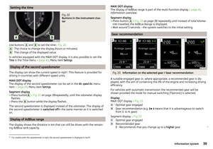 41
41 42
42 43
43 44
44 45
45 46
46 47
47 48
48 49
49 50
50 51
51 52
52 53
53 54
54 55
55 56
56 57
57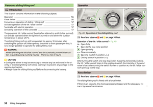 58
58 59
59 60
60 61
61 62
62 63
63 64
64 65
65 66
66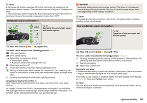 67
67 68
68 69
69 70
70 71
71 72
72 73
73 74
74 75
75 76
76 77
77 78
78 79
79 80
80 81
81 82
82 83
83 84
84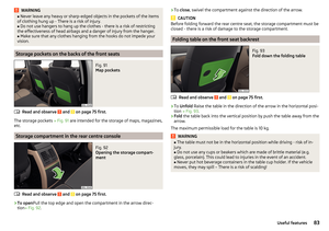 85
85 86
86 87
87 88
88 89
89 90
90 91
91 92
92 93
93 94
94 95
95 96
96 97
97 98
98 99
99 100
100 101
101 102
102 103
103 104
104 105
105 106
106 107
107 108
108 109
109 110
110 111
111 112
112 113
113 114
114 115
115 116
116 117
117 118
118 119
119 120
120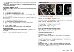 121
121 122
122 123
123 124
124 125
125 126
126 127
127 128
128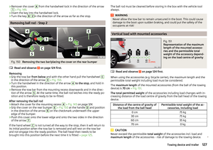 129
129 130
130 131
131 132
132 133
133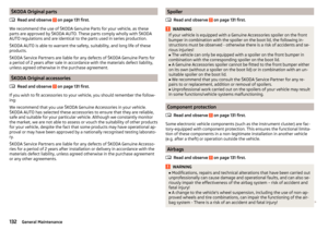 134
134 135
135 136
136 137
137 138
138 139
139 140
140 141
141 142
142 143
143 144
144 145
145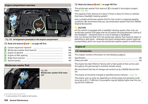 146
146 147
147 148
148 149
149 150
150 151
151 152
152 153
153 154
154 155
155 156
156 157
157 158
158 159
159 160
160 161
161 162
162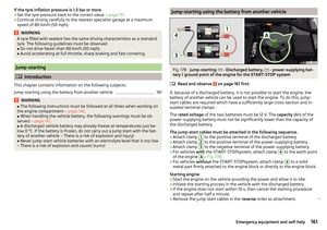 163
163 164
164 165
165 166
166 167
167 168
168 169
169 170
170 171
171 172
172 173
173 174
174 175
175 176
176 177
177 178
178 179
179 180
180 181
181 182
182 183
183 184
184 185
185 186
186 187
187 188
188 189
189 190
190 191
191 192
192 193
193 194
194 195
195 196
196 197
197 198
198 199
199