Page 89 of 200

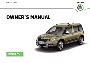
Fastening elementsFig. 100
Fasteners: Version 1/version 2
Read and observe
and on page 86 first.
The fasteners are located on both sides of the luggage compartment.
Overview of the fastening elements » Fig. 100
Lashing eyes for securing items of luggage, fastening nets and multifunc-
tion pocket
Fastening strip with integrated hook for attaching fastening nets and mul-
tifunction pocket
Lashing eyes only for fastening fixing nets
The maximum static load of the individual lashing eyes
A
is 350 kg
C
is 150
kg.
Fixing nets
Fig. 101
Fastening examples for nets
ABCRead and observe and on page 86 first.
Fastening examples for nets » Fig. 101
Horizontal pocket
Floor net
Vertical pocket
The maximum permissible load of each of the nets is 1.5 kg.
Multifunction pocket
Fig. 102
Securing the multifunction pock-
et
Read and observe and on page 86 first.
The pocket » Fig. 102 can be secured to the fastening elements
A
and
B
» Fig. 100 on page 87 .
The maximum permissible load for the bag attached to the fastening element
is 3 kg.
CAUTION
In vehicles with a variable loading floor, it is not possible to attach the bag to
the fastening elements.ABC87Transport of cargo
Page 90 of 200

Fastening bar with sliding hookFig. 103
Sliding hook onto the mounting bar / removing hook
Read and observe
and on page 86 first.
A fastening bar is located on both sides of the luggage compartment with two
moveable hooks each, in order to attach small items of luggage, such as bags,
etc.
The maximum permissible load of each of the hooks is 7.5 kg.
Moving the hook
›
Fold up the hook in direction of arrow
1
» Fig. 103 until an angle of approx.
45° is reached.
›
Move the hook in the direction of the arrow
2
into the desired position and
fold down the hook as far as the stop in direction of arrow
3
.
Removing hooks
The hook can be removed only in the rear region of the attachment bar.
›
Fold the hook upwards in direction of arrow
4
» Fig. 103 until it disengages,
and remove in the direction of arrow
5
.
Inserting hook
›
Position the hook on the fastening strip in a vertical position in direction of
arrow
5
» Fig. 103 and lightly press it on.
›
Fold the hook up to the stop away from arrow
4
until it locks.
Flexible storage compartmentFig. 104
Flexible storage compartment
Read and observe and on page 86 first.
The flexible storage compartment can be installed on the right-hand side of
the boot » Fig. 104 .
The storage compartment is designed for storing small objects with a maxi-
mum total weight of 8 kg.
›
To use ,insert the two ends of the storage compartment into the openings in
the side trim of the luggage compartment and push the shelf down to lock.
›
To remove grasp the storage compartment on both top edges, press the up-
per corners inwards and release the storage compartment by pulling up-
wards.
›
Remove the storage compartment by pulling towards you.
CAUTION
The flexible storage compartment cannot be installed on vehicles with the var-
iable loading floor.
Floor covering on both sides
Read and observe
and on page 86 first.
You can fit a double-sided floor covering in the luggage compartment. One
side is made of fabric, the other side is washable (suitable for transporting wet
or dirty items).
88Using the system
Page 91 of 200

Luggage compartment coverFig. 105
Remove the luggage compartment cover
Read and observe
and on page 86 first.
If the support straps
A
» Fig. 105 are attached to the boot lid, then opening
the lid will raise the boot lid cover (hereafter referred to as cover).
Removing
›
Partially fold the rear seat backrests forward » page 71, Adjusting the angle
of the seat backrest .
›
On both sides of the boot lid, unhook the straps
A
in the direction of arrow
1
» Fig. 105 .
›
Place the cover in the horizontal position.
›
Press on the two sides to the underside of the cover in the region of the
studs
C
in the direction of arrow
2
.
›
Fold the slackened front part of the boot cover over the head restraints of
the rear seats.
›
Slightly tilt the cover and remove.
Fitting
›
Place the cover on the contact surfaces of the side trim panel.
›
Position the mounts on the cover
B
onto the side trim panel via pins
C
» Fig. 105 .
›
Press on the two sides to the upper side of the cover in the region of the
studs
C
.
The fixture
B
must lock into place of the studs
C
on both sides of the lug-
gage compartment.
›
Unhook the straps
A
on both sides of the boot lid.
WARNINGDo not place any objects on the cover during the trip - there is a risk of in-
jury if braking suddenly or colliding!
Net partition
Fig. 106
Net partition behind the rear seats
Read and observe
and on page 86 first.
The net partition can either fitted behind the rear seats or behind the front
seats.
Fitting/removing behind the rear seats
›
Remove the luggage compartment cover » page 89, Luggage compartment
cover .
›
Remove the net partition from the bag.
›
Unfold both parts of the cross rod until they are heard to engage.
›
First insert the rod into the mount
B
» Fig. 106 on one side and push it for-
wards. In the same way, insert the cross rod into the mount
B
on the other
side of the vehicle.
›
Hang the carabines
C
at the belt ends into the lashing eyes behind the rear
seats.
›
Pull the belts through the tensioning clasp.
Removing is carried out in the reverse order.
Packing the net partition
›
Press the red button of the joint
A
» Fig. 106 . The joint is undone.
89Transport of cargo
Page 92 of 200

›Put the net partition folded together in the bag and close it.›Attach the bag with the aid of the plastic carabines to the eyes on the left
and right boot trim panel.
Installing and removing the net partition behind the rear seats with variable
loading floor is carried out in the same way as behind the rear seats without
variable loading floor. Use the lower fixing eyelets on the carrier rails in order
to attach the carabines.
Installing and removing the net partition behind the front seats is carried out
in the same way as behind the rear seats. Use the fixing eyelets on the rear of
the front seats to attach the carabines. To enlarge the boot, the rear seats can
be removed » page 72.
The opening D
» Fig. 106 in the net partition is for passing the three-point
seat belt » page 15 through.
Storage compartments
Fig. 107
Storage compartment on the left / right
Read and observe
and on page 86 first.
The cover for the storage compartment
A
» Fig. 107 can be removed, thus en-
larging the boot.
›
Grasp the top part of the cover
A
and carefully remove it in the direction of
the arrow.
The storage compartment
A
is suitable for stowing small objects weighing up
to 1.5 kg in total, and the compartment
B
up to 0.5 kg.
Removable storage boxFig. 108
Storage box
Read and observe and on page 86 first.
The storage box » Fig. 108 is placed under the variable loading floor and can be
taken out.
There is a storage space for the vehicle tool kit under the storage box
» page 155 , Vehicle tool kit .
WARNINGThe removable storage box must be located under the variable loading
floor for the safe use of the variable loading floor.
Removable lamp
Fig. 109
Removable lamp
90Using the system
Page 93 of 200

Fig. 110
Removable light: Removing / Inserting
Read and observe
and on page 86 first.
The light is located on the right side of the luggage compartment and is used
to light the luggage compartment or as a portable light.
The lamp is fitted with magnets. As a result, this can, for example, be fitted to
the vehicle body.
Description of the light » Fig. 109
Button to turn on / off the light
Part that lights up when the lamp is in the mount
Part that lights up when the lamp is not in the mount
If the light is in the mount, this will illuminate when the boot lid is opened.
›
To remove , hold the light in the area
D
and swivel in the direction of arrow
1
» Fig. 110 .
›
To switch on the removed light, press button
A
» Fig. 109. Pressing the light
again will switched it off .
›
To insert , first of all insert the light with the rear part
E
into the mount
» Fig. 110 and then push the light in the direction of arrow
2
until it audibly
clicks into place.
If the light is not switched off and is correctly inserted in the mount, the LED diodes in the front part of the light
C
» Fig. 109 are automatically switched off.
If the lamp is not correctly inserted into the holder, this does not light up when
the boot lid is opened and the rechargeable batteries are not charged.
ABCLamp charges
The lamp is supplied by three rechargeable type NiMH AAA batteries. The bat-
teries are charged continuously with the engine running (to fully charge the
battery takes approximately 3 hours).
Replace batteries » page 164.
CAUTION
The light is not waterproof, so it must be protected from humidity - otherwise
there is risk of damage.
Class N1 vehicles
Read and observe
and on page 86 first.
On class N1 vehicles, which are not fitted with a protective grille, a lashing set
which complies with the standard EN 12195 (1 - 4) must be used for fastening
the load.
Proper functioning of the electrical installation is essential for safe vehicle op-
eration. It is important to ensure that the electrical installation is not damaged
during the adjustment process or when the storage area is being loaded and
unloaded.
Variable loading floor in the luggage compartment (Estate)
Introduction
This chapter contains information on the following subjects:
Removing/fitting variable loading floor
92
Secure the variable loading floor in the raised position
92
Removing/installing the carrier rails
92
Using the variable loading floor with a spare wheel
92
The variable loading floor makes it easier to handle bulky goods and creates an
even surface when the rear seat backrests are folded forward.
The maximum permissible load of the variable loading floor is 75 kg.
91Transport of cargo
Page 94 of 200

Removing/fitting variable loading floorFig. 111
Fold up / removal variable loading floor
›
To fold together , grasp the variable loading floor on handle
A
and lift in the
direction of arrow
1
» Fig. 111 .
›
Fold up the variable loading floor in direction of arrow
2
.
›
Pull on both sides of the locking levers in direction of arrow
3
.
›
Remove the variable loading floor in direction of arrow
4
.
Insertion takes place in reverse order.
Secure the variable loading floor in the raised position
Fig. 112
Secured loading floor in the
raised position
›
Fold up the hooks on the fastening strip in direction of arrow
1
» Fig. 103 on
page 88 .
›
Fold up the variable loading floor behind the rear back backrests.
›
Fold down the hooks in direction of arrow
3
» Fig. 103 on page 88 as far as
the stop.
›
Support the variable loading floor on the hooks folded downwards » Fig. 112.
Removing/installing the carrier railsFig. 113
Slacken check points/remove carrier rails
Removing
›
Undo the securing points
B
» Fig. 113 on the carrier rails using the vehicle
key or a flat screwdriver.
›
Hold the carrier rail
A
in the front area and remove by pulling in the direction
of arrow
1
.
›
Hold the carrier rail
A
in the rear area and loosen and remove by pulling in
the direction of arrow
2
.
Fitting
›
Position the carrier rails on the sides of the boot.
›
Press the two securing points
B
» Fig. 113 on each carrier rail to the stop.
›
Check the attachment of the carrier rails by pulling it.
Using the variable loading floor with a spare wheel
Fig. 114
Fold up the side panels of the variable loading floor / space under
the variable loading floor
92Using the system
Page 95 of 200

The sides of the variable loading floor can be folded in the direction of arrow
» Fig. 114 - .
The room under the variable loading floor » Fig. 114 -
can be used to stow
the load.
Transportation on the roof rack
Roof load
The maximum permitted weight of the load incl. carriers is 100 kg.
WARNINGThe following instructions must be observed to aid road safety when trans-
porting cargo on the roof rack.■
Always distribute the load on the roof rack evenly and secure properly
with suitable lashing straps or tensioning straps.
■
When transporting heavy objects or objects which take up a large area on
the roof rack system, the handling of the car may change as a result of the
displacement of the centre of gravity. The style of driving and speed must
therefore be adapted to the current circumstances.
■
The permissible roof load, permissible axle loads and permissible total ve-
hicle weight must not be exceeded under any circumstances – risk of acci-
dent!
CAUTION
■ Make sure that the sliding / tilting roof or the boot lid does not collide with
the roof load when opened.■
Ensure the roof aerial is not impaired by the load being transported.
Note
We recommend that you use a roof rack from ŠKODA Original Accessories.Heating and ventilation
Heating, manual air conditioning system, Climatronic
Introduction
This chapter contains information on the following subjects:
Heating and manual air conditioning
94
Climatronic (automatic air conditioning)
94
Climatronic - automatic operation
95
Air distribution control
96
Air outlet vents
96
The heater heats and ventilates the vehicle interior. The air conditioning sys-
tem also cools and dehumidifies the vehicle interior.
The heating effect is dependent upon the coolant temperature, thus full heat
output only occurs when the engine has reached its operating temperature.
The cooling system works under the following conditions. The cooling system is switched on.
The engine is running.
The outside temperature is above 2 °C.
The blower is switched on.
When the cooling system is switched on, it prevents misting of the windscreen
and windows.
It is possible to boost the effectiveness of the cooling system by briefly acti-
vating the air recirculation system » page 96.
Health protection
To reduce health risks (e.g. common colds), the following instructions for the
use of the cooling system are to be observed. ▶ The difference between the outside temperature and the inside temperature
should not be greater than 5 °C.
▶ The cooling system should be turned off about 10 minutes before the end of
the journey.
▶ Once a year, a disinfection of the air conditioner is to be carried out by a spe-
cialist company.
93Heating and ventilation
Page 96 of 200

WARNING■The blower should always be on to prevent the windows from misting.
Otherwise there is a risk of accident.■
Under certain circumstances, air at a temperature of about 5 °C can flow
out of the vents when the cooling system is switched on.
Note
■ The air inlet in front of the windscreen must be free of e.g. ice, snow or
leaves to ensure that the heating and cooling system operates properly.■
After switching on the cooling Condensation from the evaporator of the air
conditioning may drip down and form a puddle below the vehicle. This is not a
leak!
■
If the coolant temperature is too high, the cooling system is switched off to
ensure that the engine cools down.
Heating and manual air conditioning
Fig. 115
Controls of the heating / air conditioning
Read and observe
on page 94 first.
Individual functions can be set or switched on by turning the dial or pressing
the corresponding button » Fig. 115.
Set the temperature
▶ Reduce the temperature /
Increase the temperature
Setting the fan speed (level 0: Fan off, level 4: high-speed)
Set the direction of the air outlet » page 96
Switching the cooling system on/off
Switch on/off the rear window heater » page 63
ABCSwitch the aux. heating and ventilation on/off » page 98
Switch recirculation on/off » page 96
When the function is switched on, the indicator light in the button lights up.
Information on cooling system
After pressing the button
the indicator light on the button lights up, even if
not all the conditions for the cooling system have been met. The cooling sys-
tem starts to work as soon as the following conditions have been met
» page 93 .
Note
To ensure adequate thermal comfort, during operation of the manual air condi-
tioning there could be an increase in the engine idle speed in some circum-
stances.
Climatronic (automatic air conditioning)
Fig. 116
Controls the Climatronic
Read and observe
on page 94 first.
Individual functions can be set or switched on by turning the dial or pressing
the corresponding button » Fig. 116.
Adjust the temperature for the left side (or for both sides)
▶ Reduce the temperature /
Increase the temperature
Interior temperature sensor
Depending on equipment fitted:
▶ Switching the windscreen heater on/off
» page 63
▶ Switch the aux. heating and ventilation on/off
» page 98
Adjust the temperature for the right side ▶ Reduce the temperature /
Increase the temperature
ABCD94Using the system
 1
1 2
2 3
3 4
4 5
5 6
6 7
7 8
8 9
9 10
10 11
11 12
12 13
13 14
14 15
15 16
16 17
17 18
18 19
19 20
20 21
21 22
22 23
23 24
24 25
25 26
26 27
27 28
28 29
29 30
30 31
31 32
32 33
33 34
34 35
35 36
36 37
37 38
38 39
39 40
40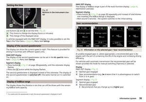 41
41 42
42 43
43 44
44 45
45 46
46 47
47 48
48 49
49 50
50 51
51 52
52 53
53 54
54 55
55 56
56 57
57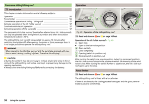 58
58 59
59 60
60 61
61 62
62 63
63 64
64 65
65 66
66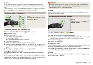 67
67 68
68 69
69 70
70 71
71 72
72 73
73 74
74 75
75 76
76 77
77 78
78 79
79 80
80 81
81 82
82 83
83 84
84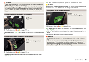 85
85 86
86 87
87 88
88 89
89 90
90 91
91 92
92 93
93 94
94 95
95 96
96 97
97 98
98 99
99 100
100 101
101 102
102 103
103 104
104 105
105 106
106 107
107 108
108 109
109 110
110 111
111 112
112 113
113 114
114 115
115 116
116 117
117 118
118 119
119 120
120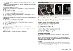 121
121 122
122 123
123 124
124 125
125 126
126 127
127 128
128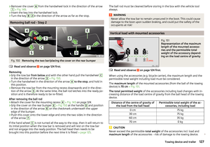 129
129 130
130 131
131 132
132 133
133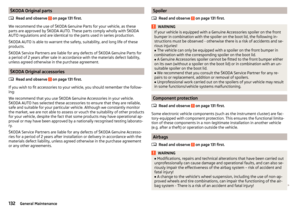 134
134 135
135 136
136 137
137 138
138 139
139 140
140 141
141 142
142 143
143 144
144 145
145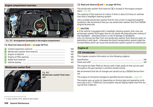 146
146 147
147 148
148 149
149 150
150 151
151 152
152 153
153 154
154 155
155 156
156 157
157 158
158 159
159 160
160 161
161 162
162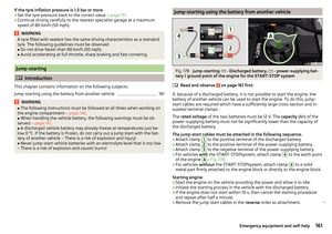 163
163 164
164 165
165 166
166 167
167 168
168 169
169 170
170 171
171 172
172 173
173 174
174 175
175 176
176 177
177 178
178 179
179 180
180 181
181 182
182 183
183 184
184 185
185 186
186 187
187 188
188 189
189 190
190 191
191 192
192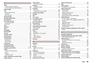 193
193 194
194 195
195 196
196 197
197 198
198 199
199