Page 153 of 200

Tyre pressureFig. 165
Label with a table of tyre sizes and tyre pressure value / inflate
tyres
The prescribed tyre inflation is on the sticker with pictograms
A
» Fig. 165 (for
some countries, the pictograms are replaced with a text).
Tyre pressure is always to match the load .
Inflation pressure for half load
Inflation pressure for environmentally friendly operation (slightly lower
fuel consumption and emissions)
Inflation pressure for full load
Tyre diameter in inches
This information serves merely as information for the prescribed tyre pres-
sure. This is not a list of shared tyre sizes for your vehicle. These are in the
vehicle's technical documentation, in the declaration of conformity (in so-
called COC document) and listed on the vehicle data » page 175.
Tyre pressure value on the front axle
Tyre pressure value on the rear axle
Check tyre pressures
Check the tyre pressure, including that of the spare wheel, at least once a
month and also before setting off on a long journey.
Always check the inflation pressure when the tyres are cold. Do not reduce the
higher pressure of warm tyres.
In vehicles with tyre pressure monitoring, tyre pressure values must be saved
each time the pressures are changed » page 123.
BCDEFGWARNING■
Do not drive with incorrect tyre pressure - There is a risk of accident.■In the event of very rapid pressure loss (e.g. in the event of tyre damage)
an attempt should be made to bring the vehicle carefully to a stop without
sudden steering movements and without any hard braking - risk of acci-
dent.
Note
The declaration of conformity (COC document), can be obtained from a ŠKODA 1)
partner.
Tyre wear and wheel change
Fig. 166
Tyre wear indicator / wheel change
Tyre wear increases in the following circumstances.
▶ Incorrect tyre pressures.
▶ Driving style (e.g. fast cornering, rapid acceleration / braking).
▶ Incorrect wheel balancing (you should have the wheels balanced after
changing/repair tyres or if the steering “is drifting”).
▶ Wheel alignment errors.
There are wear indicator markers in the tyre profiles, indicating whether the
minimum permissible tread depth has been reached » Fig. 166 -
. A tyre
should be regarded as worn out when this indicator is flush with the tread.
Markings on the walls of the tyres with the letters “TWI” and/or other symbols (e.g.
), identify the position of the wear indicators.
1)
Only valid for some countries and some models.
151Wheels
Page 154 of 200

To ensure uniform wear on all tyres, we recommend that you change the
wheels every 10 000 km, in line with the schedule » Fig. 166 - .WARNING■
Change the tyres at the latest when they are worn down to the wear indi-
cators -There is a risk of an accident.■
Faulty wheel alignment affects handling - There is a risk of an accident.
■
Unusual vibrations or the vehicle “pulling ” to one side could be a sign of
tyre damage. Reduce speed and stop! If there are no external signs of tyre
damage, seek the help of a specialist garage.
Spare wheel
Only use this emergency spare wheel to reach the nearest specialist garage, as
it is not intended for permanent use .
A warning label is always placed on the rim of the temporary spare wheel.
Please note the following if you intend to use the temporary spare wheel. ▶ Do not cover the warning sign.
▶ Be particularly observant when driving.
▶ Inflate the emergency spare to the maximum inflation pressure for the vehi-
cle » page 151 .
In vehicles with tyre pressure monitoring, save the tyre pressure values in the
system » page 123 .
WARNING■
Never drive with more than one spare wheel mounted!■Avoid full throttle acceleration, sharp braking and fast cornering when
driving with the temporary spare wheel.■
Do not use snow chains on the temporary spare wheel.
■
Observe instructions on the warning sign of the emergency wheel.
Tyre marking
Explanation of tyre markings - e.g. 225/50 R 17 91 T
225Tyre width in mm50Height/width ratio in %RCode letter for the type of tyre – Radial17Diameter of wheel in inches91Load indexTSpeed symbol
Load index - indicates the maximum permissible load for each individual tyre
Load index90919293949597Load
(In kg)600615630650670690730
Speed symbol - indicates the maximum permissible speed for a vehicle fitted
with tyres in a given category
Speed
symbolSTUHVWYMaximum speed
(in km/h)180190200210240270300WARNINGNever exceed the maximum permissible load bearing capacity and speed
for the tyres fitted – There is a risk of accident.
Operating in winter conditions
All-year (or “winter”) tyres
All-year or “winter”tyres (indicated by an M+S or a mountain peak/snowflake
symbol ) to improve the performance of the vehicle in winter conditions.
To get the best possible driving characteristics, all-year or “winter”tyres, with a
minimum tread depth of 4 mm on all four wheels, should be fitted.
If “winter” tyres are mounted, summer tyres should be fitted again in good
time as they provide better handling properties, a shorter braking distance,
less tyre noise and reduced tyre wear on roads which are free of snow and ice
as well as at temperatures above 7 °C.
Speed symbol
All-year or “winter”tyres (marked with M+S and a peak/snowflake symbol
) of
a lower speed category than listed in the vehicle’s technical documentation
can be used provided that the maximum permissible speed for these tyres is
not exceeded even if the maximum possible speed of the vehicle is higher.
152General Maintenance
Page 155 of 200

The speed limit for all-season or “winter”Tires can be adjusted in MAXI
DOTDisplay in the menu item winter tires
» page 43 .
If the vehicle has all-season or “winter”tires of a lower speed category then
the specified maximum speed of the vehicle (referring to tyres that have not
been delivered by the factory, a warning label with the maximum value of the
speed category provided for the mounted tyres must be fixed in the interior of
the vehicle in a constantly visible place in the driver’s field of vision. The warn-
ing label (sticker) can be replaced by setting maximum value of the mounted
tire speed rating in the MAXI DOTDisplay in the
winter tires
menu item 1)
. This
specification defines the maximum vehicle speed with mounted all-season or
“winter”tyres that may not be exceeded.
Snow chains
The snow chains improve handling in wintry road conditions.
Remove the full wheel trims before installing the snow chains » page 156.
Only fit snow chains with links and locks not larger than 12 mm.
The use of snow chains on vehicles with front-wheel drive and on vehicles
with four-wheel drive differs.
Front-wheel drive
Snow chains must only be fitted on the front wheels and are applicable only to
the following wheel / tyre combinations.
Rim sizePress depth DTyre size6J x 1650 mm205/55 R167J x 1645 mm205/55 R166J x 1745 mm205/50 R17
All-wheel drive
Snow chains can be mounted on the wheels on the front and rear axles.
It is only permissible to fit snow chains on the front wheels with the following
wheel/tyre combinations.
Rim sizePress depth DTyre size6J x 1650 mm205/55 R167J x 1645 mm205/55 R166J x 1745 mm205/50 R17
It is only permissible to fit snow chains on the rear wheels with the following
wheel/tyre combinations.
Rim sizePress depth DTyre size7J x 1645 mm215/60 R167J x 1745 mm225/50 R17WARNINGDo not use chains on snow and ice-free routes - the handling would be im-
paired and there is a risk of damage to the tyres.1)
Valid in certain countries.
153Wheels
Page 156 of 200

Do-it-yourself
Emergency equipment and self-help
Emergency equipment
Introduction
This chapter contains information on the following subjects:
Placement of the first aid kit and warning triangle
154
Location of reflective vest
154
Fire extinguisher
154
Vehicle tool kit
155
Placement of the first aid kit and warning triangle
Fig. 167
Location of the first-aid kit and the warning triangle
The following information applies for the first aid kit and warning triangle from the ŠKODA Original Accessories.
Placing the first-aid kit
The first-aid box can be attached by a strap to the right-hand side of the boot
» Fig. 167 -
.
Placing of the warning triangle
The warning triangle can be attached using the tensioning straps in the recess
of the loading edge » Fig. 167 -
.
The warning triangle, which is included in the equipment with the spare wheel,
can be stowed in a removable box on the right next to the spare wheel
» page 91 .
WARNINGProperly secure the first aid kit and the warning triangle - there is a risk of
injury in the event of sudden braking or a vehicle collision.
Location of reflective vest
Fig. 168
Storage compartment for the re-
flective vest
The reflective vest can be stowed in a holder under the driver's seat » Fig. 168.
Fire extinguisher
Fig. 169
Release the fire extinguisher
The fire extinguisher is attached by two straps in a holder underneath the driv-
er's seat.
›
To remove the fire extinguisher, release the safety catches on the two belts
in the direction of arrow » Fig. 169 and remove the fire extinguisher.
›
To secure , place the fire extinguisher back in the mount and secure with the
belts.
The Owner's Manual is fitted next to the fire extinguisher.
Pay attention to the expiration date of the fire extinguisher. After this date,
the correct function of the device is not guaranteed.
154Do-it-yourself
Page 157 of 200

WARNINGAlways properly secure the fire extinguisher - there is a risk of injury in the
event of sudden braking or a vehicle collision.
Vehicle tool kit
Fig. 170
Vehicle tool kit
The box containing the vehicle tool kit is located in the storage compartment
for the spare wheel, and can be secured with a tape depending on the equip-
ment fitted.
Depending on the vehicle configuration, it may not contain all the compo-
nents listed in the on-board tool kit.
Screwdriver
Key for removing and installing the tail light
Top section for the anti-theft wheel bolts
Towing eye
Clamps for removing the wheel trims
Jack with sign
Wheel wrench
Extraction pliers for the wheel bolt caps
Breakdown kit
123456789WARNING■ The factory-supplied lifting jack is only intended for your model of vehicle.
Under no circumstances attempt to lift other vehicles or loads with it –
there is a risk of injury.■
Always securely stow the tool in the box and make sure that it is secured
to the spare wheel using the tape - Otherwise there is a risk of injury in the
event of sudden braking or a vehicle collision.
CAUTION
Screw the jack back to its starting position prior to putting it back in its box -
There is a risk of damage to the box.
Note
The declaration of conformity is included with the jack or the log folder.
Changing a wheel
Preliminary work
For safety's sake, the following instructions must be observed before
changing a wheel on the road.
›
Park the vehicle as far as possible away from the traffic flow - choose a place
with a flat and firm surface.
›
Switch off the engine.
›
For vehicles with manual transmission , select 1 gear.
›
For vehicles with automatic transmission , place the selector lever in the P
position.
›
Firmly apply the handbrake.
›
Switch on the hazard warning lights and set up the warning triangle at the
prescribed distance.
›
Have all the occupants get out . The passengers should not stand on the
road while the wheel is being changed (they should remain behind a crash
barrier, for instance).
›
Uncouple any trailers.
Changing a wheel
›
Remove the spare wheel » page 156.
›
Remove the full wheel trim » page 156 or caps » page 157 .
›
Loosen the wheel bolts » page 158 » .
155Emergency equipment and self-help
Page 158 of 200
.
›
Remove the wheel c")
›Jack up the vehicle
» page 158 until the wheel that needs changing is clear of
the ground.›
Unscrew the wheel bolts and place them on a clean surface (cloth, paper,
etc.).
›
Remove the wheel carefully.
›
Attach the spare wheel and slightly screw on the wheel bolts.
›
Lower the vehicle.
›
Tighten the wheel bolts opposite each other using the wheel wrench (“pull- ing crossways”) » page 158.
›
Replace the wheel trim » page 156 and caps » page 157 .
When fitting unidirectional tyres, ensure that the direction of rotation is cor-
rect » page 150 .
All bolts must be clean and must turn easily. If screws are corroded and diffi-
cult to move, these must be replaced.
WARNING■ Undo the wheel bolts just a little (about one turn), provided the vehicle
has not yet been jacked up. Otherwise the wheel could come loose and fall
off – risk of injury.■
Under no circumstances must the bolts be greased or oiled - cause an ac-
cident.
Subsequent steps
After changing the wheel, the following work must be carried out.
›
Stow the replaced wheel in the well under the floor covering of the luggage
compartment and secure with a locking screw.
›
Stow the vehicle tool kit in the space provided.
›
Check tyre pressure on the mounted wheel and adjust if necessary and, with
vehicles with tyre pressure monitoring, save the tyre pressure values in the
system » page 123 .
›
Have the tightening torque of the wheel bolts checked as soon as possible.
The prescribed tightening torque is 120 Nm.
Replace the damaged wheel or consult a specialist garage about repair op-
tions.
WARNINGTightening torque which is too high can damage the threads and this can
result in permanent deformation of the contact surfaces on the rim. Where
tightening torque is too low, the wheels may become loose while driving -
There is a risk of an accident. Therefore drive cautiously and only at a mod-
erate speed until the tightening torque has been checked.
Removing /stowing the spare wheel
Fig. 171
Take out the wheel
The spare wheel is located in a well under the floor covering in the luggage
compartment and is fixed in place with a fastening screw.
Take out the wheel
›
Lift up the floor in the luggage compartment.
›
Unscrew the locking screw in the direction of arrow » Fig. 171 and the remove
the wheel.
›
Remove the box with the tool kit.
Store wheel away
›
Store the box for the vehicle tools in the same place.
›
Place the wheel into the wheel well with the wheel rim pointing downwards.
›
Screw the locking screw against the direction of arrow until it stops » Fig. 171.
›
Fold back the floor in the luggage compartment.
Full wheel trim
Remove trim
›
Hang the clamps for removing the full wheel trims on the edge of the full
wheel trim.
›
Push the wheel wrench through the clamp, support on the tyre and pull off
the wheel trim.
156Do-it-yourself
Page 159 of 200

Install trim›Press the wheel trim onto the wheel rim at the designated valve opening.›
Then press the trim into the wheel rim until its entire circumference locks
correctly in place.
The position of the anti-theft wheel bolt is indicated by means of a symbol on
the back of the wheel trim supplied ex-factory or from the ŠKODA Original Ac-
cessories. If using the anti-theft wheel bolt it should be fitted at this point
»
.
WARNINGIf wheel trims are fitted, an adequate flow of air must be assured in order
to cool the brake system - otherwise there is a risk of an accident.
CAUTION
■ If the wheel trim is positioned outside the position marked for the anti-theft
wheel bolt, there is a risk of damaging the wheel cover.■
Only use manual pressure and do not hit the full wheel trim – there is a risk
of damaging the trim.
Note
We recommend that you use wheel trims from ŠKODA Original Accessories.
Wheel bolts
Fig. 172
Remove the cap
›
To remove the cap , insert the extraction pliers as far as they will go on the
cap and pulling them out in the direction of arrow » Fig. 172.
›
To install , insert the cap onto the wheel bolt as far as it will go.
Anti-theft wheel boltsFig. 173
Anti-theft wheel bolt and attach-
ment
The anti-theft wheel bolts protect the wheels from theft. This can only be
B
with attachment » Fig. 173loosened / tightened .
›
Insert the attachment
B
» Fig. 173 as far as it will go on the anti-theft wheel
bolt
A
.
›
Insert the key as far as it will go onto attachment
B
and loosen / tighten the
wheel bolt.
›
Remove the attachment.
The attachment for the anti-theft wheel bolts must always be kept in the ve-
hicle in case of a possible wheel change.
For wheel trims supplied ex-factory or from ŠKODA Original Accessories, the
anti-theft wheel bolt should be installed in the position marked on the back of
the wheel trim » page 156.
Note
The attachment and the anti-theft wheel bolts are provided with a code num-
ber. A replacement attachment can be ordered from ŠKODA Genuine Accesso-
ries using this.157Emergency equipment and self-help
Page 160 of 200

Loosening/tightening wheel boltsFig. 174
Loosening the wheel bolts
›
Insert the wheel wrench onto the wheel bolt to the stop. Use the associated
attachment for the anti-theft wheel bolts » Fig. 173 on page 157 .
›
To loosen the screws , grasp the key end and turn the screw about one turn
rotation in the direction of the arrow » Fig. 174.
›
Totighten the screws , grasp the key end and turn the screw about against
the direction of the arrow » Fig. 174, until it is tight.
WARNINGIf it proves difficult to undo the bolts, carefully apply pressure to the end of
the wrench with your foot. Keep hold of the vehicle when doing so, and
make sure you keep your footing - danger of injury.
Raising the vehicle
Fig. 175
Jacking points for the jack
Fig. 176
Attach lifting jack
Before the vehicle is raised, please take note of the safety instructions »
.
Use the jack from the tool kit to raise the vehicle. Position the car jack at the
jacking point closest to the flat tyre.
The runner connectors for the jack are located directly below the marking on
the lower loading edge of the vehicle » Fig. 175.
›
Position the base plate of the jack with its full area resting on level ground
and ensure that the jack will fit in the jacking point when raised » Fig. 176 -
.
›
Use the crank to raise the jack until its pawl covers the jacking
point » Fig. 176 -
.
›
Raise the vehicle until the wheel is a little off the floor.
WARNINGThe following instructions must be observed, otherwise there is risk of in-
jury.■
Ensure the vehicle cannot unexpectedly roll away.
■
Always ensure the base plate of the lifting jack cannot slip.
■ Place a wide and stable base material under the jack if on a loose surfa-
ces (e.g. gravel).
■ Place an anti-slip base material (e.g. a rubber mat) under the jack if on a
smooth surface (e.g. cobblestones).
■
Always raise the vehicle with the doors closed.
■
Never position any body parts (e.g. arms or legs) under the vehicle while
the vehicle is raised.
■
When the vehicle is raised, never start the engine.
158Do-it-yourself
 1
1 2
2 3
3 4
4 5
5 6
6 7
7 8
8 9
9 10
10 11
11 12
12 13
13 14
14 15
15 16
16 17
17 18
18 19
19 20
20 21
21 22
22 23
23 24
24 25
25 26
26 27
27 28
28 29
29 30
30 31
31 32
32 33
33 34
34 35
35 36
36 37
37 38
38 39
39 40
40 41
41 42
42 43
43 44
44 45
45 46
46 47
47 48
48 49
49 50
50 51
51 52
52 53
53 54
54 55
55 56
56 57
57 58
58 59
59 60
60 61
61 62
62 63
63 64
64 65
65 66
66 67
67 68
68 69
69 70
70 71
71 72
72 73
73 74
74 75
75 76
76 77
77 78
78 79
79 80
80 81
81 82
82 83
83 84
84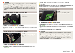 85
85 86
86 87
87 88
88 89
89 90
90 91
91 92
92 93
93 94
94 95
95 96
96 97
97 98
98 99
99 100
100 101
101 102
102 103
103 104
104 105
105 106
106 107
107 108
108 109
109 110
110 111
111 112
112 113
113 114
114 115
115 116
116 117
117 118
118 119
119 120
120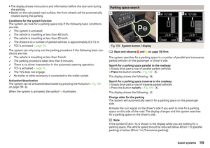 121
121 122
122 123
123 124
124 125
125 126
126 127
127 128
128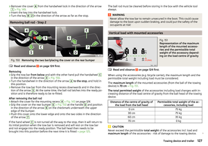 129
129 130
130 131
131 132
132 133
133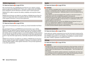 134
134 135
135 136
136 137
137 138
138 139
139 140
140 141
141 142
142 143
143 144
144 145
145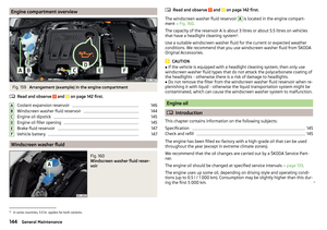 146
146 147
147 148
148 149
149 150
150 151
151 152
152 153
153 154
154 155
155 156
156 157
157 158
158 159
159 160
160 161
161 162
162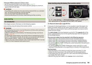 163
163 164
164 165
165 166
166 167
167 168
168 169
169 170
170 171
171 172
172 173
173 174
174 175
175 176
176 177
177 178
178 179
179 180
180 181
181 182
182 183
183 184
184 185
185 186
186 187
187 188
188 189
189 190
190 191
191 192
192 193
193 194
194 195
195 196
196 197
197 198
198 199
199