2009 SUBARU TRIBECA clutch
[x] Cancel search: clutchPage 2114 of 2453
5AT-98
AT Main Case
AUTOMATIC TRANSMISSION
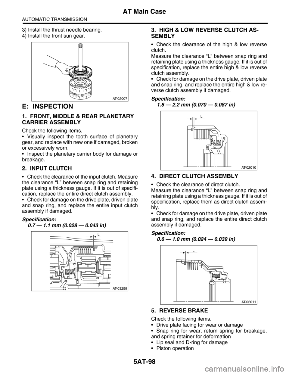
3) Install the thrust needle bearing.
4) Install the front sun gear.
E: INSPECTION
1. FRONT, MIDDLE & REAR PLANETARY
CARRIER ASSEMBLY
Check the following items.
•Visually inspect the tooth surface of planetary
gear, and replace with new one if damaged, broken
or excessively worn.
•Inspect the planetary carrier body for damage or
breakage.
2. INPUT CLUTCH
•Check the clearance of the input clutch. Measure
the clearance “L” between snap ring and retaining
plate using a thickness gauge. If it is out of specifi-
cation, replace the entire direct clutch assembly.
•Check for damage on the drive plate, driven plate
and snap ring, and replace the entire input clutch
assembly if damaged.
Specification:
0.7 — 1.1 mm (0.028 — 0.043 in)
3. HIGH & LOW REVERSE CLUTCH AS-
SEMBLY
•Check the clearance of the high & low reverse
clutch.
Measure the clearance “L” between snap ring and
retaining plate using a thickness gauge. If it is out of
specification, replace the entire high & low reverse
clutch assembly.
•Check for damage on the drive plate, driven plate
and snap ring, and replace the entire high & low re-
verse clutch assembly if damaged.
Specification:
1.8 — 2.2 mm (0.070 — 0.087 in)
4. DIRECT CLUTCH ASSEMBLY
•Check the clearance of direct clutch.
Measure the clearance “L” between snap ring and
retaining plate using a thickness gauge. If it is out of
specification, replace them as direct clutch assem-
bly.
•Check for damage on the drive plate, driven plate
and snap ring, and replace the entire direct clutch
assembly if damaged.
Specification:
0.6 — 1.0 mm (0.024 — 0.039 in)
5. REVERSE BRAKE
Check the following items.
•Drive plate facing for wear or damage
•Snap ring for wear, return spring for breakage,
and spring retainer for deformation
•Lip seal and D-ring for damage
•Piston operation
AT-02007
AT-03259
L
AT-02010
L
AT-02011
L
Page 2119 of 2453
5AT(diag)-2
Basic Diagnostic Procedure
AUTOMATIC TRANSMISSION (DIAGNOSTICS)
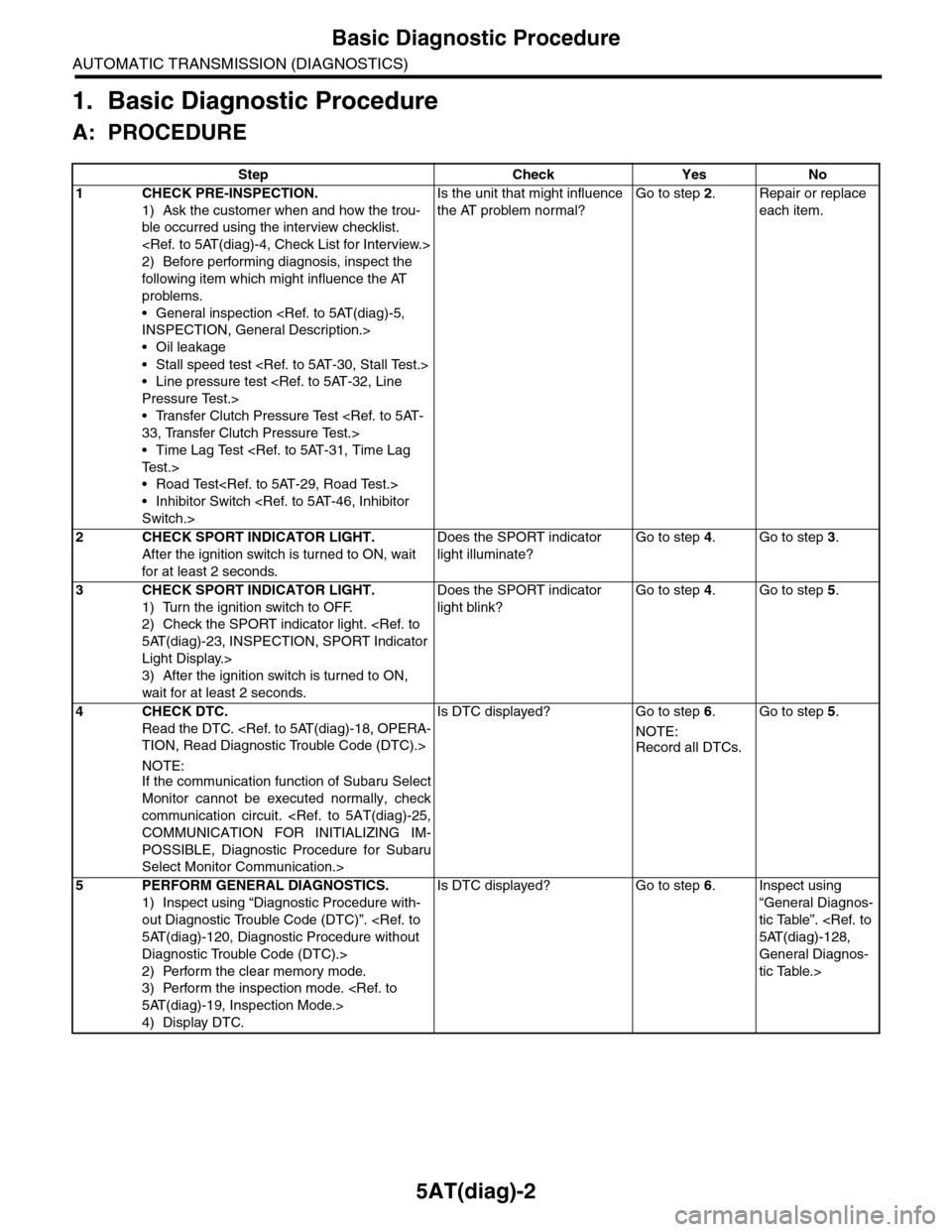
1. Basic Diagnostic Procedure
A: PROCEDURE
Step Check Yes No
1CHECK PRE-INSPECTION.
1) Ask the customer when and how the trou-
ble occurred using the interview checklist.
2) Before performing diagnosis, inspect the
following item which might influence the AT
problems.
•General inspection
•Oil leakage
•Stall speed test
•Line pressure test
•Transfer Clutch Pressure Test
•Time Lag Test
•Road Test
•Inhibitor Switch
Is the unit that might influence
the AT problem normal?
Go to step 2.Repair or replace
each item.
2CHECK SPORT INDICATOR LIGHT.
After the ignition switch is turned to ON, wait
for at least 2 seconds.
Does the SPORT indicator
light illuminate?
Go to step 4.Go to step 3.
3CHECK SPORT INDICATOR LIGHT.
1) Turn the ignition switch to OFF.
2) Check the SPORT indicator light.
Light Display.>
3) After the ignition switch is turned to ON,
wait for at least 2 seconds.
Does the SPORT indicator
light blink?
Go to step 4.Go to step 5.
4CHECK DTC.
Read the DTC.
NOTE:If the communication function of Subaru Select
Monitor cannot be executed normally, check
communication circuit.
POSSIBLE, Diagnostic Procedure for Subaru
Select Monitor Communication.>
Is DTC displayed? Go to step 6.
NOTE:
Record all DTCs.
Go to step 5.
5PERFORM GENERAL DIAGNOSTICS.
1) Inspect using “Diagnostic Procedure with-
out Diagnostic Trouble Code (DTC)”.
Diagnostic Trouble Code (DTC).>
2) Perform the clear memory mode.
3) Perform the inspection mode.
4) Display DTC.
Is DTC displayed? Go to step 6.Inspect using
“General Diagnos-
tic Table”.
General Diagnos-
tic Table.>
Page 2127 of 2453
5AT(diag)-10
Electrical Component Location
AUTOMATIC TRANSMISSION (DIAGNOSTICS)
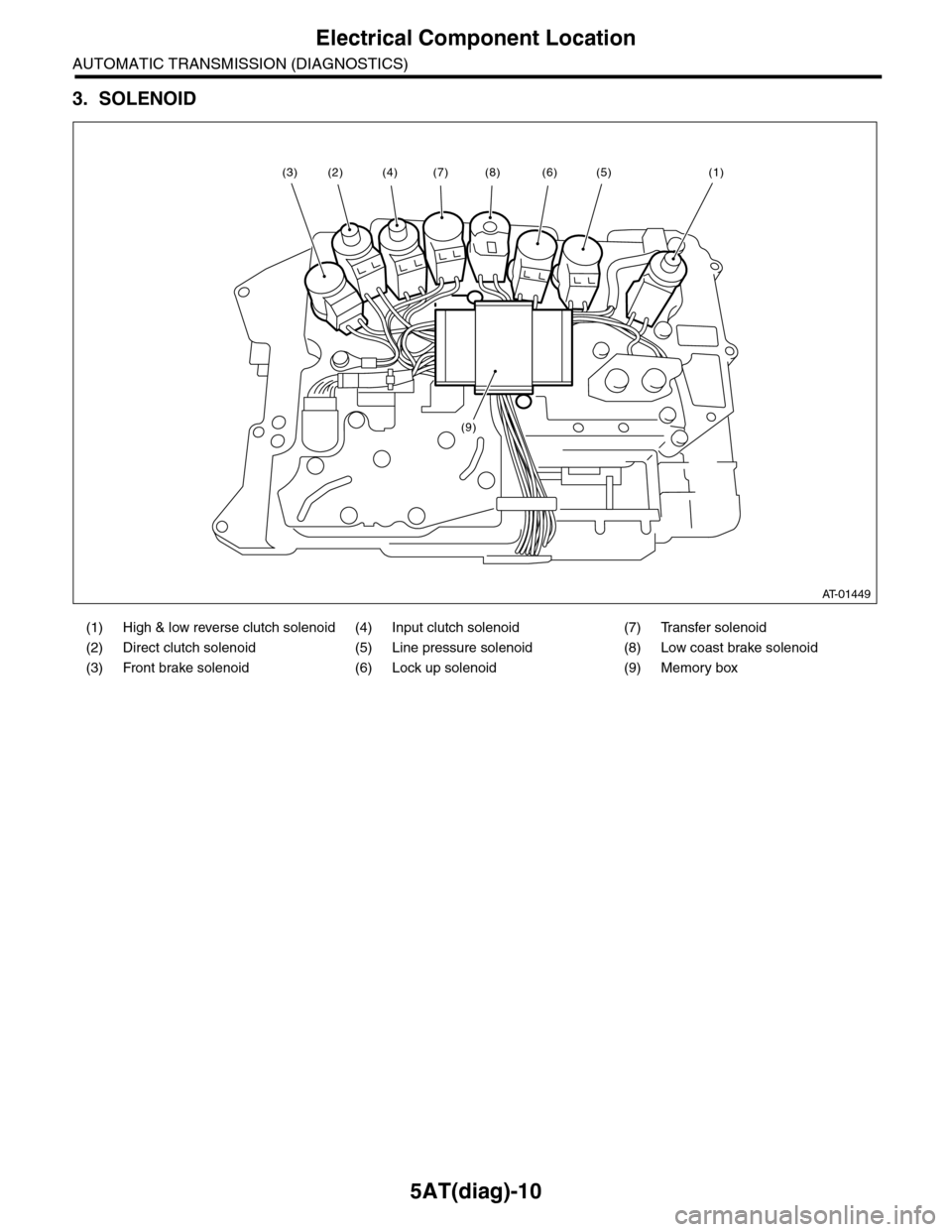
3. SOLENOID
(1) High & low reverse clutch solenoid (4) Input clutch solenoid (7) Transfer solenoid
(2) Direct clutch solenoid (5) Line pressure solenoid (8) Low coast brake solenoid
(3) Front brake solenoid (6) Lock up solenoid (9) Memory box
AT-01449
(8)(6)(5)(1)(7)
(9)
(4)(2)(3)
Page 2133 of 2453
5AT(diag)-16
Subaru Select Monitor
AUTOMATIC TRANSMISSION (DIAGNOSTICS)
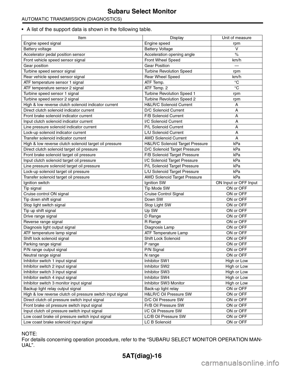
•A list of the support data is shown in the following table.
NOTE:
For details concerning operation procedure, refer to the “SUBARU SELECT MONITOR OPERATION MAN-
UAL”.
Item Display Unit of measure
Engine speed signal Engine speed rpm
Battery voltage Battery Voltage V
Accelerator pedal position sensor Acceleration opening angle %
Fr o nt veh ic l e sp e ed se n so r s ig n al Fr o n t W h ee l S p e ed km/ h
Gear position Gear Position —
Tu r b i n e s p e e d s e n s o r s i g n a l Tu r b i n e R e v o l u t i o n S p e e d r p m
Rear vehicle speed sensor signal Rear Wheel Speed km/h
ATF temperature sensor 1 signal ATF Temp. °C
ATF temperature sensor 2 signal ATF Temp. 2 °C
Tu r b i n e s p e e d s e n s o r 1 s i g n a l Tu r b i n e R e v o l u t i o n S p e e d 1 r p m
Tu r b i n e s p e e d s e n s o r 2 s i g n a l Tu r b i n e R e v o l u t i o n S p e e d 2 r p m
High & low reverse clutch solenoid indicator current H&LR/C Solenoid Current A
Direct clutch solenoid indicator current D/C Solenoid Current A
Fr o nt b rake so l en oi d in di c at o r c u rr e n t F / B S o l en o id Cur r e nt A
Input clutch solenoid indicator current I/C Solenoid Current A
Line pressure solenoid indicator current P/L Solenoid Current A
Lock-up solenoid indicator current L/U Solenoid Current A
Tr a n s f e r s o l e n o i d i n d i c a t o r c u r r e n t A W D S o l e n o i d C u r r e n t A
High & low reverse clutch solenoid target oil pressure H&LR/C Solenoid Target Pressure kPa
Direct clutch solenoid target oil pressure D/C Solenoid Target Pressure kPa
Fr o nt b rake so l en oi d ta r g et o il pr e ss ur e F / B S o l en o id Ta r g et P r es su r e kPa
Input clutch solenoid target oil pressure I/C Solenoid Target Pressure kPa
Line pressure solenoid target oil pressure P/L Solenoid Target Pressure kPa
Lock-up solenoid target oil pressure L/U Solenoid Target Pressure kPa
Tr a n s f e r s o l e n o i d t a r g e t o i l p r e s s u r e A W D S o l e n o i d Ta r g e t P r e s s u r e k P a
Ignition switch Ignition SW ON Input or OFF Input
Tip signal Tip Mode SW ON or OFF
Cruise control ON signal Cruise Control Signal ON or OFF
Tip down shift signal Down SW ON or OFF
Stop light switch signal Stop Light SW ON or OFF
Tip up shift signal Up SW ON or OFF
Drive range signal D Range ON or OFF
Reverse range signal R Range ON or OFF
Diagnosis light output signal Diagnosis Lamp ON or OFF
AT F t e m p e r a t u r e l a m p s i g n a l AT F Te m p e r a t u r e L a m p O N o r O F F
Shift lock solenoid signal Shift Lock Solenoid ON or OFF
Par king range signal P range ON or OFF
P/N range output signal P/N Signal ON or OFF
Neutral range signal N range ON or OFF
Inhibitor switch 1 input signal Inhibitor SW1 High or Low
Inhibitor switch 2 input signal Inhibitor SW2 High or Low
Inhibitor switch 3 input signal Inhibitor SW3 High or Low
Inhibitor switch 4 input signal Inhibitor SW4 High or Low
Inhibitor switch 3 monitor input signal Inhibitor SW3 Monitor High or Low
Backup light relay output signal Back-up light relay ON or OFF
High & low reverse clutch oil pressure switch input signal H&LR/C Oil Pressure SW ON or OFF
Direct clutch oil pressure switch input signal D/C Oil Pressure SW ON or OFF
Fr o nt b rake oi l pr e ss ur e swi tc h i n pu t si gn a l Fr / B Oi l P r e ss ur e S W ON or OF F
Input clutch oil pressure switch input signal I/C Oil Pressure SW ON or OFF
Low coast brake oil pressure switch input signal LC/B Oil Pressure SW ON or OFF
Low coast brake solenoid input signal LC B Solenoid ON or OFF
Page 2138 of 2453
5AT(diag)-21
Learning Control
AUTOMATIC TRANSMISSION (DIAGNOSTICS)
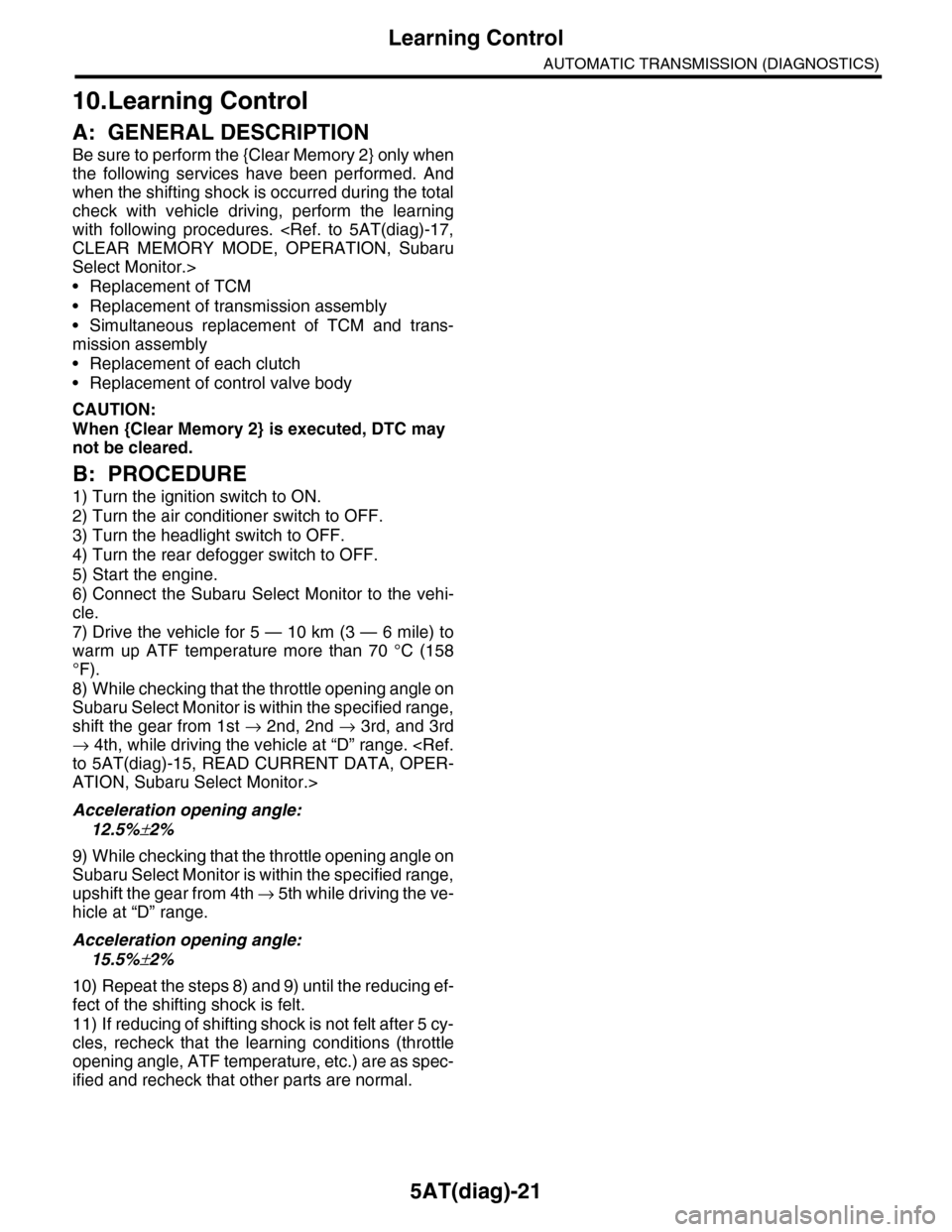
10.Learning Control
A: GENERAL DESCRIPTION
Be sure to perform the {Clear Memory 2} only when
the following services have been performed. And
when the shifting shock is occurred during the total
check with vehicle driving, perform the learning
with following procedures.
Select Monitor.>
•Replacement of TCM
•Replacement of transmission assembly
•Simultaneous replacement of TCM and trans-
mission assembly
•Replacement of each clutch
•Replacement of control valve body
CAUTION:
When {Clear Memory 2} is executed, DTC may
not be cleared.
B: PROCEDURE
1) Turn the ignition switch to ON.
2) Turn the air conditioner switch to OFF.
3) Turn the headlight switch to OFF.
4) Turn the rear defogger switch to OFF.
5) Start the engine.
6) Connect the Subaru Select Monitor to the vehi-
cle.
7) Drive the vehicle for 5 — 10 km (3 — 6 mile) to
warm up ATF temperature more than 70 °C (158
°F).
8) While checking that the throttle opening angle on
Subaru Select Monitor is within the specified range,
shift the gear from 1st → 2nd, 2nd → 3rd, and 3rd
→ 4th, while driving the vehicle at “D” range.
ATION, Subaru Select Monitor.>
Acceleration opening angle:
12.5%±2%
9) While checking that the throttle opening angle on
Subaru Select Monitor is within the specified range,
upshift the gear from 4th → 5 t h w h i l e d r i v i n g t h e v e -
hicle at “D” range.
Acceleration opening angle:
15.5%±2%
10) Repeat the steps 8) and 9) until the reducing ef-
fect of the shifting shock is felt.
11) If reducing of shifting shock is not felt after 5 cy-
cles, recheck that the learning conditions (throttle
opening angle, ATF temperature, etc.) are as spec-
ified and recheck that other parts are normal.
Page 2145 of 2453
5AT(diag)-28
List of Diagnostic Trouble Code (DTC)
AUTOMATIC TRANSMISSION (DIAGNOSTICS)
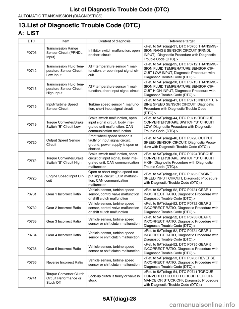
13.List of Diagnostic Trouble Code (DTC)
A: LIST
DTC Item Content of diagnosis Reference target
P0705
Tr a n s m i s s i o n R a n g e
Sensor Circuit (PRNDL
Input)
Inhibitor switch malfunction, open
or short circuit
INPUT), Diagnostic Procedure with Diagnostic
Tr o u b l e C o d e ( D T C ) . >
P0712
Tr a n s m i s s i o n F l u i d Te m -
perature Sensor Circuit
Low Input
AT F t e m p e r a t u r e s e n s o r 1 m a l -
function, or open input signal cir-
cuit
CUIT LOW INPUT, Diagnostic Procedure with
Diagnostic Trouble Code (DTC).>
P0713
Tr a n s m i s s i o n F l u i d Te m -
perature Sensor Circuit
High Input
AT F t e m p e r a t u r e s e n s o r 1 m a l -
function, short input signal circuit
CUIT HIGH INPUT, Diagnostic Procedure with
Diagnostic Trouble Code (DTC).>
P0715Input/Turbine Speed
Sensor Circuit
Tu r b i n e s p e e d s e n s o r 1 m a l f u n c -
tion, short input signal circuit
Procedure with Diagnostic Trouble Code
(DTC).>
P0719To r q u e C o n v e r t e r / B r a k e
Switch “B” Circuit Low
Brake switch malfunction, open
input signal circuit, body inte-
grated unit malfunction, CAN
communication malfunction
LOW, Diagnostic Procedure with Diagnostic
Tr o u b l e C o d e ( D T C ) . >
P0720Output Speed Sensor
Circuit
Front wheel speed sensor is
faulty or input signal circuit,
ground, power supply is open or
shorted.
dure with Diagnostic Trouble Code (DTC).>
P0724To r q u e C o n v e r t e r / B r a k e
Switch “B” Circuit High
Brake switch malfunction, short
circuit of input signal, body inte-
grated unit, CAN communication
malfunction
HIGH, Diagnostic Procedure with Diagnostic
Tr o u b l e C o d e ( D T C ) . >
P0725Engine Speed Input Cir-
cuit
Open or short engine speed out-
put signal circuit, ECM malfunc-
tion, CAN communication
malfunction
with Diagnostic Trouble Code (DTC).>
P0731 Gear 1 Incorrect Ratio
Ve h i c l e s e n s o r, t u r b i n e s p e e d
sensor, control valve malfunction
or shift clutch malfunction
Diagnostic Trouble Code (DTC).>
P0732 Gear 2 Incorrect Ratio
Ve h i c l e s e n s o r, t u r b i n e s p e e d
sensor, control valve malfunction
or shift clutch malfunction
Diagnostic Trouble Code (DTC).>
P0733 Gear 3 Incorrect RatioVe h i c l e s e n s o r, t u r b i n e s p e e d
sensor or shift clutch malfunction
Diagnostic Trouble Code (DTC).>
P0734 Gear 4 Incorrect RatioVe h i c l e s e n s o r, t u r b i n e s p e e d
sensor or shift clutch malfunction
Diagnostic Trouble Code (DTC).>
P0735 Gear 5 Incorrect RatioVe h i c l e s e n s o r, t u r b i n e s p e e d
sensor or shift clutch malfunction
Diagnostic Trouble Code (DTC).>
P0736 Reverse Incorrect RatioVe h i c l e s e n s o r, t u r b i n e s p e e d
sensor or shift clutch malfunction
Diagnostic Trouble Code (DTC).>
P0741
To r q u e C o n v e r t e r C l u t c h
Circuit Performance or
Stuck Off
Lock-up clutch is faulty or valve is
stuck.
MANCE OR STUCK OFF, Diagnostic Procedure
with Diagnostic Trouble Code (DTC).>
Page 2146 of 2453
5AT(diag)-29
List of Diagnostic Trouble Code (DTC)
AUTOMATIC TRANSMISSION (DIAGNOSTICS)
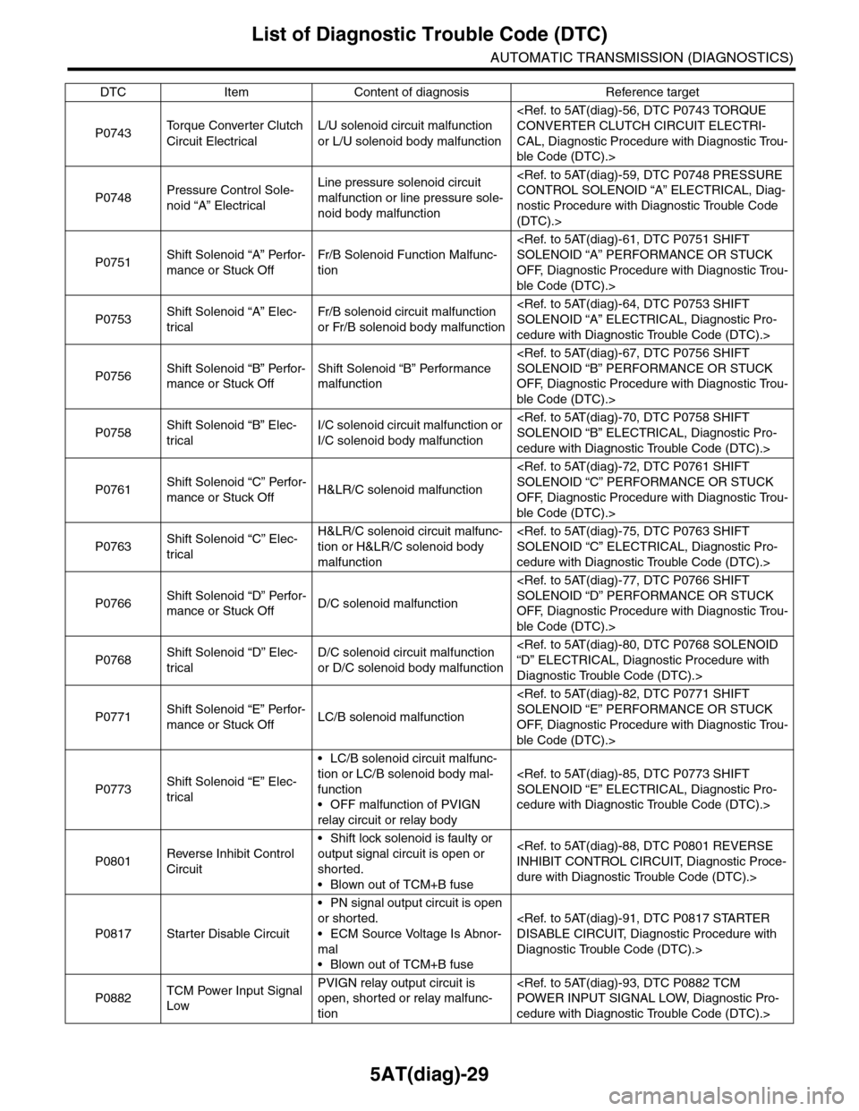
P0743To r q u e C o n v e r t e r C l u t c h
Circuit Electrical
L/U solenoid circuit malfunction
or L/U solenoid body malfunction
CAL, Diagnostic Procedure with Diagnostic Trou-
ble Code (DTC).>
P0748Pressure Control Sole-
noid “A” Electrical
Line pressure solenoid circuit
malfunction or line pressure sole-
noid body malfunction
nostic Procedure with Diagnostic Trouble Code
(DTC).>
P0751Shift Solenoid “A” Perfor-
mance or Stuck Off
Fr/B Solenoid Function Malfunc-
tion
OFF, Diagnostic Procedure with Diagnostic Trou-
ble Code (DTC).>
P0753Shift Solenoid “A” Elec-
trical
Fr/B solenoid circuit malfunction
or Fr/B solenoid body malfunction
cedure with Diagnostic Trouble Code (DTC).>
P0756Shift Solenoid “B” Perfor-
mance or Stuck Off
Shift Solenoid “B” Performance
malfunction
OFF, Diagnostic Procedure with Diagnostic Trou-
ble Code (DTC).>
P0758Shift Solenoid “B” Elec-
trical
I/C solenoid circuit malfunction or
I/C solenoid body malfunction
cedure with Diagnostic Trouble Code (DTC).>
P0761Shift Solenoid “C” Perfor-
mance or Stuck OffH&LR/C solenoid malfunction
OFF, Diagnostic Procedure with Diagnostic Trou-
ble Code (DTC).>
P0763Shift Solenoid “C” Elec-
trical
H&LR/C solenoid circuit malfunc-
tion or H&LR/C solenoid body
malfunction
cedure with Diagnostic Trouble Code (DTC).>
P0766Shift Solenoid “D” Perfor-
mance or Stuck OffD/C solenoid malfunction
OFF, Diagnostic Procedure with Diagnostic Trou-
ble Code (DTC).>
P0768Shift Solenoid “D” Elec-
trical
D/C solenoid circuit malfunction
or D/C solenoid body malfunction
Diagnostic Trouble Code (DTC).>
P0771Shift Solenoid “E” Perfor-
mance or Stuck OffLC/B solenoid malfunction
OFF, Diagnostic Procedure with Diagnostic Trou-
ble Code (DTC).>
P0773Shift Solenoid “E” Elec-
trical
•LC/B solenoid circuit malfunc-
tion or LC/B solenoid body mal-
function
•OFF malfunction of PVIGN
relay circuit or relay body
cedure with Diagnostic Trouble Code (DTC).>
P0801Reverse Inhibit Control
Circuit
•Shift lock solenoid is faulty or
output signal circuit is open or
shorted.
•Blown out of TCM+B fuse
dure with Diagnostic Trouble Code (DTC).>
P0817 Starter Disable Circuit
•PN signal output circuit is open
or shorted.
•ECM Source Voltage Is Abnor-
mal
•Blown out of TCM+B fuse
Diagnostic Trouble Code (DTC).>
P0882TCM Power Input Signal
Low
PVIGN relay output circuit is
open, shorted or relay malfunc-
tion
cedure with Diagnostic Trouble Code (DTC).>
DTC Item Content of diagnosis Reference target
Page 2147 of 2453
5AT(diag)-30
List of Diagnostic Trouble Code (DTC)
AUTOMATIC TRANSMISSION (DIAGNOSTICS)
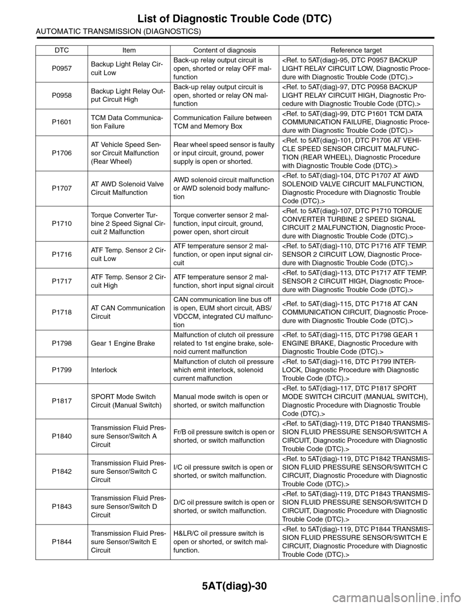
P0957Backup Light Relay Cir-
cuit Low
Back-up relay output circuit is
open, shorted or relay OFF mal-
function
dure with Diagnostic Trouble Code (DTC).>
P0958Backup Light Relay Out-
put Circuit High
Back-up relay output circuit is
open, shorted or relay ON mal-
function
cedure with Diagnostic Trouble Code (DTC).>
P1601TCM Data Communica-
tion Failure
Communication Failure between
TCM and Memory Box
dure with Diagnostic Trouble Code (DTC).>
P1706
AT Ve h i c l e S p e e d S e n -
sor Circuit Malfunction
(Rear Wheel)
Rear wheel speed sensor is faulty
or input circuit, ground, power
supply is open or shorted.
TION (REAR WHEEL), Diagnostic Procedure
with Diagnostic Trouble Code (DTC).>
P1707AT A W D S o l e n o i d V a l v e
Circuit Malfunction
AWD solenoid circuit malfunction
or AWD solenoid body malfunc-
tion
Diagnostic Procedure with Diagnostic Trouble
Code (DTC).>
P1710
To r q u e C o n v e r t e r Tu r -
bine 2 Speed Signal Cir-
cuit 2 Malfunction
To r q u e c o n v e r t e r s e n s o r 2 m a l -
function, input circuit, ground,
power open, short circuit
CIRCUIT 2 MALFUNCTION, Diagnostic Proce-
dure with Diagnostic Trouble Code (DTC).>
P1716AT F Te m p . S e n s o r 2 C i r -
cuit Low
AT F t e m p e r a t u r e s e n s o r 2 m a l -
function, or open input signal cir-
cuit
dure with Diagnostic Trouble Code (DTC).>
P1717AT F Te m p . S e n s o r 2 C i r -
cuit High
AT F t e m p e r a t u r e s e n s o r 2 m a l -
function, short input signal circuit
dure with Diagnostic Trouble Code (DTC).>
P1718AT C A N C o m m u n i c a t i o n
Circuit
CAN communication line bus off
is open, EUM short circuit, ABS/
VDCCM, integrated CU malfunc-
tion
dure with Diagnostic Trouble Code (DTC).>
P1798 Gear 1 Engine Brake
Malfunction of clutch oil pressure
related to 1st engine brake, sole-
noid current malfunction
Diagnostic Trouble Code (DTC).>
P1799 Interlock
Malfunction of clutch oil pressure
which emit interlock, solenoid
current malfunction
Tr o u b l e C o d e ( D T C ) . >
P1817SPORT Mode Switch
Circuit (Manual Switch)
Manual mode switch is open or
shorted, or switch malfunction
Diagnostic Procedure with Diagnostic Trouble
Code (DTC).>
P1840
Tr a n s m i s s i o n F l u i d P r e s -
sure Sensor/Switch A
Circuit
Fr/B oil pressure switch is open or
shorted, or switch malfunction
CIRCUIT, Diagnostic Procedure with Diagnostic
Tr o u b l e C o d e ( D T C ) . >
P1842
Tr a n s m i s s i o n F l u i d P r e s -
sure Sensor/Switch C
Circuit
I/C oil pressure switch is open or
shorted, or switch malfunction.
CIRCUIT, Diagnostic Procedure with Diagnostic
Tr o u b l e C o d e ( D T C ) . >
P1843
Tr a n s m i s s i o n F l u i d P r e s -
sure Sensor/Switch D
Circuit
D/C oil pressure switch is open or
shorted, or switch malfunction.
CIRCUIT, Diagnostic Procedure with Diagnostic
Tr o u b l e C o d e ( D T C ) . >
P1844
Tr a n s m i s s i o n F l u i d P r e s -
sure Sensor/Switch E
Circuit
H&LR/C oil pressure switch is
open or shorted, or switch mal-
function.
CIRCUIT, Diagnostic Procedure with Diagnostic
Tr o u b l e C o d e ( D T C ) . >
DTC Item Content of diagnosis Reference target